Table of Contents
Advertisement
Quick Links
Please file and use this manual together with the service manual for Model No. CU-2S18SKH
CU-3S28SBH CU-4S34SBH, Order No. PAPAMY16011007CE.
This service information is designed for experienced repair technicians only and is not designed for use by the general public.
It does not contain warnings or cautions to advise non-technical individuals of potential dangers in attempting to service a product.
Products powered by electricity should be serviced or repaired only by experienced professional technicians. Any attempt to
service or repair the products dealt with in this service information by anyone else could result in serious injury or death.
There are special components used in this equipment which are important for safety. These parts are marked by
Diagrams, Circuit Board Diagrams, Exploded Views and Replacement Parts List. It is essential that these critical parts should be
replaced with manufacturer's specified parts to prevent shock, fire or other hazards. Do not modify the original design without permission
of manufacturer.
In order to avoid frostbite, be assured of no refrigerant leakage during the installation or repairing of refrigerant circuit.
AIR CONDITIONER
MODE
OFF/ON
POWERFUL
QUIET
MODE
FAN SPEED
TEMP
TIMER
ON
SET
1
2
3
OFF
CANCEL
AC
RC
SET
CHECK
CLOCK
RESET
WARNING
IMPORTANT SAFETY NOTICE
PRECAUTION OF LOW TEMPERATURE
Order No: PAPAMY1611009CE
Indoor Unit
CS-MS9SD3H
CS-MS12SD3H
CS-MS18SD3H
CS-MS24SD3H
Destination
Brunei
Myanmar
Cambodia
Thailand
Indonesia
Vietnam
CU-3S27SBH
CU-4S27SBH
in the Schematic
© Panasonic Corporation 2016
Advertisement
Table of Contents

Related Manuals for Panasonic CS-MS9SD3H


Summary of Contents for Panasonic CS-MS9SD3H
- Page 1 Do not modify the original design without permission of manufacturer. PRECAUTION OF LOW TEMPERATURE In order to avoid frostbite, be assured of no refrigerant leakage during the installation or repairing of refrigerant circuit. © Panasonic Corporation 2016...
-
Page 2: Table Of Contents
TABLE OF CONTENTS PAGE PAGE Safety Precautions ..........3 Specifications ............. 5 Location of Controls and Components ..15 Indoor Unit ..........15 Remote Control .......... 15 Dimensions ............16 ... -
Page 3: Safety Precautions
1. Safety Precautions Read the following “SAFETY PRECAUTIONS” carefully before installation. Electrical work must be installed by a licensed electrician. Be sure to use the correct rating of the power plug and main circuit for the model to be installed. ... - Page 4 WARNING During installation, install the refrigerant piping properly before running the compressor. Operation of compressor without fixing refrigeration piping and valves at opened position will cause suck-in of air, abnormal high pressure in refrigeration cycle and result in explosion, injury etc. During pump down operation, stop the compressor before removing the refrigeration piping.
-
Page 5: Specifications
2. Specifications Model Indoor/Outdoor CS-MS9SD3H/CU-3S28SBH CS-MS12SD3H/CU-3S28SBH Performance Test Condition Phase, Hz Single, 50 Single, 50 Power Supply Min. Mid. Max. Min. Mid. Max. 1.70 2.80 3.40 1.70 3.20 4.00 Capacity BTU/h 5800 9550 11600 5800 10900 13600 kJ/h 6120 10080... - Page 6 Model Indoor/Outdoor CS-MS9SD3H/CU-3S28SBH CS-MS12SD3H/CU-3S28SBH DRY BULB WET BULB DRY BULB WET BULB Maximum °C Indoor Operation Range Minimum °C Cooling capacities are based on indoor temperature of 27°C DRY BULB (80.6°F DRY BULB), 19.0°C WET BULB (66°F WET BULB) and outdoor air temperature of 35°C DRY BULB (95°F DRY BULB), 24°C WET BULB (75.2°F WET BULB)
- Page 7 Model Indoor/Outdoor CS-MS18SD3H/CU-3S28SBH CS-MS24SD3H/CU-3S28SBH Performance Test Condition Phase, Hz Single, 50 Single, 50 Power Supply Min. Mid. Max. Min. Mid. Max. 1.90 5.00 5.80 1.90 6.00 6.20 Capacity BTU/h 6480 17100 19800 6480 20500 21100 kJ/h 6840 18000 20880 6840 21600 22320 Running Current...
- Page 8 Model Indoor/Outdoor CS-MS18SD3H/CU-3S28SBH CS-MS24SD3H/CU-3S28SBH DRY BULB WET BULB DRY BULB WET BULB Maximum °C Indoor Operation Range Minimum °C Cooling capacities are based on indoor temperature of 27°C DRY BULB (80.6°F DRY BULB), 19.0°C WET BULB (66°F WET BULB) and outdoor air temperature of 35°C DRY BULB (95°F DRY BULB), 24°C WET BULB (75.2°F WET BULB) Specifications are subject to change without notice for further improvement.
- Page 9 Example: The indoor units’ combination below is possible to connect to CU-3S27SBH. (Total nominal capacity of indoor units is between 5.6 kW to 13.2 kW) 1) Two CS-MS9SD3H only. (Total nominal cooling capacity is 5.6 kW) 2) One CS-MS9SD3H and Two CS-MS12SD3H. (Total nominal cooling capacity is 9.2 kW) Indoor Unit: CS-MS9/12SD3H ...
- Page 10 Cooling Capacity (kW) Input Power (W) Current, 50Hz, Indoor unit capacity MOISTURE REMOVAL VOLUME 220V / 240V Cooling Total min ~ max Rating min ~ max 2.8 + 2.8 + 2.8 7.50 2.4 ~ 7.6 2740 580 ~ 3170 13.5 / 12.4 1.5 + 1.5 + 1.5 2.8 + 2.8 + 3.2 7.50...
- Page 11 Cooling Capacity (kW) Input Power (W) Current, 50Hz, Indoor unit capacity MOISTURE REMOVAL VOLUME 220V / 240V Cooling Total min ~ max Rating min ~ max 2.8 + 2.8 + 2.8 7.50 2.4 ~ 7.9 2740 580 ~ 2840 13.4 / 12.3 1.5 + 1.5 + 1.5 2.8 + 2.8 + 3.2 7.50...
- Page 12 Cooling Capacity (kW) Input Power (W) Current, 50Hz, Indoor unit capacity MOISTURE REMOVAL VOLUME 220V / 240V Cooling Total min ~ max Rating min ~ max 2.8 + 2.8 + 2.8 + 2.8 7.50 2.8 ~ 8.0 2060 520 ~ 2650 10.2 / 9.4 1.2 + 1.2 + 1.2 + 1.2 2.8 + 2.8 + 2.8 + 3.2...
- Page 13 Cooling Capacity ANNUAL Input Power (W) Current, MOISTURE REMOVAL (kW) Indoor unit capacity ENERGY 50Hz, 220V / VOLUME Cooling CONSUMPTION 240V (A) Total min ~ max Rating min ~ max CLASS (kWh) 3.2 + 3.2 + 6.0 10.00 2.9 ~ 10.7 3040 390 ~ 3540 3.29...
- Page 14 Cooling Capacity ANNUAL Input Power (W) Current, MOISTURE REMOVAL (kW) Indoor unit capacity ENERGY 50Hz, 220V / VOLUME Cooling CONSUMPTION 240V (A) Total min ~ max Rating min ~ max CLASS (kWh) 3.2 + 3.2 + 3.2 + 6.0 10.00 2.9 ~ 11.0 2860 510 ~ 3530...
-
Page 15: Location Of Controls And Components
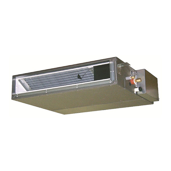
Location of Controls and Components Indoor Unit Air inlet Air outlet Remote control receiver Indicator POWER (Green) (Orange) TIMER (Orange) POWERFUL (Orange) QUIET Remote Control AIR CONDITIONER MODE Remote control display OFF/ON Powerful operation Quiet operation OFF/ON POWERFUL QUIET Operation mode Fan Speed selection MODE FAN SPEED... -
Page 16: Dimensions
4. Dimensions Indoor Unit <Front View> DUCT INSTALLATION HOLE (AIR OUTLET DUCT FLANGE) <Top View> <Side View> 160 × 4 = 640 <Side View> WATER INLET DRAIN PORT (UPPER & LOWER) <Back View> <Receiver> (AIR INLET) AIR FILTER <Remote Control> AIR CONDITIONER MODE OFF/ON... -
Page 17: Refrigeration Cycle Diagram
5. Refrigeration Cycle Diagram INDOOR LIQUID SIDE 2-WAY VALVE PIPE TEMP. SENSOR 1 INTAKE TEMP. PIPE SENSOR (INLET) TEMP. SENSOR 2 HEAT EXCHANGER (EVAPORATOR) SIDE 3-WAY VALVE COOLING... -
Page 18: Block Diagram
6. Block Diagram Indoor Unit FUSE... -
Page 19: Wiring Connection Diagram
7. Wiring Connection Diagram Indoor Unit FLOAT SWITCH ELECTRONIC HAJEM-A CN-CNT CONTROLLER MOTOR (WHT) (WHITE) CN-FM (WHITE) CN-FSW (GREEN) RECTIFICATION CIRCUIT INDOOR PIPE TEMPERATURE DRAIN PUMP t˚ SENSOR 2 INDOOR PIPE CN-TH TEMPERATURE CN-DRMTR1 NOISE FILTER (WHITE) t˚ SENSOR 1 (BLUE) CIRCUIT INDOOR AIR... -
Page 20: Electronic Circuit Diagram
8. Electronic Circuit Diagram Indoor Unit... -
Page 21: Printed Circuit Board
9. Printed Circuit Board Indoor Unit 9.1.1 Main Printed Circuit Board CN-T1 CN-AC CN-T2 CN-DRMTR1 CN-FM CN-TH CN-FSW CN-DISP... -
Page 22: Installation Instruction
10. Installation Instruction Attached accessories Accessory part Qty. Accessory part Qty. Accessory part Qty. Remote control Receiver fixing screw Clamper (band) (M4 x 15.5 mm) (for flare & drain insulating connection) Clamper (band) Drain hose Battery (for receiver cable fixing) (for unit &... -
Page 23: Indoor Unit
10.1 Indoor Unit 10.1.1 Selecting the Installation Location Take into consideration the following contents when creating the blueprint. ■ Indoor unit installation location Do not install the unit in excessive oil fume area such as kitchen, workshop and etc. ... - Page 24 Required Minimum Space for Installation and Service 824 (Suspension bolt pitch) Electrical component box Min. Inspection 200 or access more 450 x 450 Refrigerant tubing Min. 650 or more Flange for air outlet duct Min. 20 or more Min. 20 or more Min.
- Page 25 Dimension of the Indoor Unit 692 (Flange for air outlet duct) 640 (160x4) 2-ø3.1(Hole) 5-ø3.1(Hole) Inspection access (450x450) (Field supply) 824 (Suspension bolt pitch) 10-ø3.1(Hole) * Filter Uninstalled In Case of Bottom Intake Dummy hole Air intake Cover plate Remove the frame filter assy as shown in ○...
- Page 26 Ceiling Opening Install inspection opening (450 mm × 450 mm) on the control box side where maintenance and inspection of the control box and drain pump are easy. Install another inspection opening (800 mm × 700 mm) also at the lower part of the unit.
- Page 27 Installation into the Ceiling Attach the nuts and washers to the hanging bolts, then lift up and hook the main unit onto the hanging fixtures. Check if the unit is leveled using a level or a vinyl hose filled partially with water. Hanging bolt (M10) (locally purchased) washer...
- Page 28 3. Connect the indoor unit and the remote control receiver . (Refer to the illustration.) 4. Insert firmly the connector of receiver cable to connector at control box of indoor unit. 5. Fix the green wire from receiver cable to the grounding location provided inside control board. Receiver cable 8 Control box Connector...
- Page 29 EMBEDDED TYPE Preparation: Make 2 holes for screws using a driver. Mount the top case. Mount the bottom case to the wall. • Align the claws of the • Pass the wire through the hole in top case and then the centre of the bottom case.
- Page 30 10.1.4 Connecting the Drain Piping Lay the drain piping so as to ensure drainage. Use a locally purchased VP20 general rigid PVC pipe (outer diameter ø26) for the drain piping and firmly connect the indoor unit and the drain piping using supplied hose band to ensure that no leakage occurs. ...
- Page 31 10.1.6 Connecting the Indoor/Outdoor Connection Cable Remove the control box cover and insert the Ensure the colour of wires of outdoor unit and the connection cable into the control box. terminal Nos. are the same to the indoor’s ...
- Page 32 10.1.6.1 Wire Stripping and Connecting Requirement Wire stripping Conductor not Conductor Conductor fully inserted fully inserted over inserted Indoor/outdoor connection terminal board 5 mm No loose strand or more when inserted ACCEPT PROHIBITED PROHIBITED (gap between wires) Do not joint wires WARNING RISK OF FIRE JOINING OF WIRES MAY CAUSE...
-
Page 33: Operation And Control
11. Operation and Control 11.1 Basic Function Inverter control, which equipped with a microcomputer in determining the most suitable operating mode as time passes, automatically adjusts output power for maximum comfort always. In order to achieve the suitable operating mode, the microcomputer maintains the set temperature by measuring the temperature of the environment and performing temperature shifting. - Page 34 11.1.4 Automatic Operation This mode can be set using remote control and the operation is decided by remote control setting temperature, remote control operation mode and indoor intake air temperature. During operation mode judgment, indoor fan motor (with speed of Lo-) is running for 30 seconds to detect the indoor intake air temperature.
-
Page 35: Quiet Operation (Cooling Mode/Cooling Area Of Soft Dry Mode)
11.2 Quiet Operation (Cooling Mode/Cooling Area of Soft Dry Mode) A. Purpose To provide quiet cooling operation compare to normal operation. B. Control condition a. Quiet operation start condition When “quiet” button at remote control is pressed. Quiet LED illuminates. b. -
Page 36: Auto Restart Control
11.5 Auto Restart Control When the power supply is cut off during the operation of air conditioner, the compressor will re-operate within three to four minutes (there are 10 patterns between 2 minutes 58 seconds and 3 minutes 52 seconds to be selected randomly) after power supply resumes. -
Page 37: Servicing Mode
12. Servicing Mode 12.1 TEST RUN OPERATION (FOR PUMP DOWN/SERVICING PURPOSE) The Test Run operation will be activated by short-circuiting CN-S (Pin 1 & 2) at outdoor unit PCB after power supplied to outdoor unit terminal 1 and 2. The unit forced to run rated frequency cooling operation mode. -
Page 38: Troubleshooting Guide
13. Troubleshooting Guide 13.1 Refrigeration Cycle System In order to diagnose malfunctions, make sure that there are no Normal Pressure and Outlet Air Temperature (Standard) electrical problems before inspecting the refrigeration cycle. Gas pressure Outlet air Such problems include insufficient insulation, problem with the MPa (kg/cm temperature (°C) power source, malfunction of a compressor and a fan. -
Page 39: Relationship Between The Condition Of The Air Conditioner And Pressure And Electric Current
13.2 Relationship Between the Condition of the Air Conditioner and Pressure and Electric Current Cooling Mode Condition of the air conditioner Low Pressure High Pressure Electric current during operation Insufficient refrigerant (gas leakage) Clogged capillary tube ... -
Page 40: Breakdown Self Diagnosis Function
13.3 Breakdown Self Diagnosis Function 13.3.1 Self Diagnosis Function (Three Digits Alphanumeric Code) Once error occurred during operation, the unit will stop its operation, and Timer LED blinks. Although Timer LED goes off when power supply is turned off, if the unit is operated under a breakdown condition, the LED will ON again. -
Page 41: Error Codes Table
13.4 Error Codes Table Diagnosis Abnormality Emergency Abnormality / Protection control Primary location to verify display Judgment Operation No abnormality detected ─ Normal operation ─ Internal / external cable connections > 1 min. after Indoor fan Indoor / outdoor abnormal communication starting operation operation only ... - Page 42 Diagnosis Abnormality Emergency Abnormality / Protection control Primary location to verify display Judgment Operation Excess refrigerant IPM (power transistor) overheating Improper heat radiation ─ ─ protection IPM (Power transistor) Insufficient refrigerant Outdoor compressor overheating 4 times occurrence ─...
-
Page 43: Self-Diagnosis Method
13.5 Self-diagnosis Method 13.5.1 H11 (Indoor/Outdoor Abnormal Communication) Malfunction Decision Conditions During startup and operation of cooling, the data received from outdoor unit in indoor unit signal transmission is checked whether it is normal. Malfunction Caused Faulty indoor unit PCB. ... - Page 44 13.5.2 H12 (Indoor/Outdoor Capacity Rank Mismatched) Malfunction Decision Conditions During startup, error code appears when different types of indoor and outdoor units are interconnected. Malfunction Caused Wrong models interconnected. Wrong indoor unit or outdoor unit PCBs mounted. ...
- Page 45 13.5.3 H14 (Indoor Intake Air Temperature Sensor Abnormality) Malfunction Decision Conditions During startup and operation of cooling, the temperatures detected by the indoor intake air temperature sensor are used to determine sensor errors. Malfunction Caused Faulty connector connection. ...
- Page 46 13.5.4 H15 (Compressor Temperature Sensor Abnormality) Malfunction Decision Conditions During startup and operation of cooling, the temperatures detected by the outdoor compressor temperature sensor are used to determine sensor errors. Malfunction Caused Faulty connector connection. Faulty sensor. ...
- Page 47 13.5.5 H16 (Outdoor Current Transformer) Malfunction Decision Conditions An input current, detected by Current Transformer CT, is below threshold value when the compressor is operating at certain frequency value for 3 minutes. Malfunction Caused Lack of gas Broken CT (current transformer) ...
- Page 48 13.5.6 H19 (Indoor Fan Motor – DC Motor Mechanism Locked) Malfunction Decision Conditions The rotation speed detected by the Hall IC during fan motor operation is used to determine abnormal fan motor (feedback of rotation > 2550 rpm or < 50 rpm) Malfunction Caused ...
- Page 49 13.5.7 H23 (Indoor Pipe Temperature Sensor Abnormality) Malfunction Decision Conditions During startup and operation of cooling, the temperatures detected by the indoor heat exchanger temperature sensor are used to determine sensor errors. Malfunction Caused Faulty connector connection. Faulty sensor.
- Page 50 13.5.8 H24 (Indoor Pipe Temperature Sensor 2 Abnormality) Malfunction Decision Conditions During startup and operation of cooling, the temperatures detected by the indoor heat exchanger temperature sensor 2 are used to determine sensor errors. Malfunction Caused Faulty connector connection. ...
- Page 51 13.5.9 H27 (Outdoor Air Temperature Sensor Abnormality) Malfunction Decision Conditions During startup and operation of cooling, the temperatures detected by the outdoor air temperature sensor are used to determine sensor errors. Malfunction Caused Faulty connector connection. Faulty sensor. ...
- Page 52 13.5.10 H28 (Outdoor Pipe Temperature Sensor Abnormality) Malfunction Decision Conditions During startup and operation of cooling, the temperatures detected by the outdoor pipe temperature sensor are used to determine sensor errors. Malfunction Caused Faulty connector connection. Faulty sensor. ...
- Page 53 13.5.11 H30 (Compressor Discharge Temperature Sensor Abnormality) Malfunction Decision Conditions During startup and operation of cooling, the temperatures detected by the outdoor discharge pipe temperature sensor are used to determine sensor errors. Malfunction Caused Faulty connector connection. Faulty sensor.
- Page 54 13.5.12 H33 (Unspecified Voltage between Indoor and Outdoor) Malfunction Decision Conditions The supply power is detected for its requirement by the indoor/outdoor transmission. Malfunction Caused Wrong models interconnected. Wrong indoor unit and outdoor unit PCBs used. Indoor unit or outdoor unit PCB defective.
- Page 55 13.5.13 H97 (Outdoor Fan Motor – DC Motor Mechanism Locked) Malfunction Decision Conditions The rotation speed detected by the Hall IC during fan motor operation is used to determine abnormal fan motor. Malfunction Caused Operation stops due to short circuit inside the fan motor winding. ...
- Page 56 13.5.14 H98 (Error Code Stored in Memory and no alarm is triggered / no TIMER LED flashing) Malfunction Decision Conditions Indoor high pressure is detected when indoor heat exchanger is detecting very high temperature when the unit is operating in heating operation. ...
- Page 57 13.5.15 H99 (Indoor Freeze Prevention Protection: Cooling or Soft Dry) Error Code will not display (no Timer LED blinking) but store in EEPROM Malfunction Decision Conditions Freeze prevention control takes place (when indoor pipe temperature is lower than 2°C) Malfunction Caused ...
- Page 58 13.5.16 F11 (Indoor Pipe Temperature Sensor Abnormality) Malfunction Decision Conditions When cooling operation, when indoor pipe temperature or indoor heat exchanger temperature sensor is above 45°C. Malfunction Caused Faulty connector connection. Faulty indoor pipe temperature sensor. Faulty indoor main PCB Troubleshooting When abnormality indication starts again...
- Page 59 13.5.17 F90 (Power Factor Correction Protection) Malfunction Decision Conditions To maintain DC voltage level supply to power transistor. To detect high DC voltage level after rectification. Malfunction Caused During startup and operation of cooling and heating, when Power Factor Correction (PFC) protection circuitry at the outdoor unit main PCB senses abnormal DC voltage level for power transistors.
- Page 60 13.5.18 F91 (Refrigeration Cycle Abnormality) Malfunction Decision Conditions The input current is low while the compressor is running at higher than the setting frequency. Malfunction Caused Lack of gas. 3-way valve close. Troubleshooting When F91 indication happens For safety reason and to prevent component breakdown, always switch Caution...
- Page 61 13.5.19 F93 (Compressor Rotation Failure) Malfunction Decision Conditions A compressor rotation failure is detected by checking the compressor running condition through the position detection circuit. Malfunction Caused Compressor terminal disconnect Faulty Outdoor PCB Faulty compressor Troubleshooting For safety reason and to prevent component When F93 indication happens breakdown, always switch off the power...
- Page 62 13.5.20 F95 (Outdoor High Pressure Protection: Cooling or Soft Dry) Malfunction Decision Conditions During operation of cooling or soft dry, when outdoor unit heat exchanger high temperature data is detected by the outdoor unit heat exchanger thermistor. Malfunction Caused ...
- Page 63 13.5.21 F96 (IPM Overheating) Malfunction Decision Conditions During operating of cooling and heating, when IPM temperature data (100°C) is detected by the IPM temperature sensor. Multi Models only Compressor Overheating: During operation of cooling and heating, when the compressor OL is activated. Heat Sink Overheating: During operation of cooling and heating, when heat sink temperature data (90°C) is detected by the heat sink temperature sensor.
- Page 64 13.5.22 F97 (Compressor Overheating) Malfunction Decision Conditions During operation of cooling, when compressor tank temperature data (112°C) is detected by the compressor tank temperature sensor. Malfunction Caused Faulty compressor tank temperature sensor 2/3 way valve closed Refrigerant shortage (refrigerant leakage) ...
- Page 65 13.5.23 F98 (Input Over Current Detection) Malfunction Decision Conditions During operation of cooling, when an input over-current (X value in Total Running Current Control) is detected by checking the input current value being detected by current transformer (CT) with the compressor running. Malfunction Caused ...
- Page 66 13.5.24 F99 (DC Peak Detection) Malfunction Decision Conditions During startup and operation of cooling, when inverter DC peak data is received by the outdoor internal DC Peak sensing circuitry. Malfunction Caused DC current peak due to compressor failure. DC current peak due to defective power transistor(s).
-
Page 67: Disassembly And Assembly Instructions
14. Disassembly and Assembly Instructions WARNING High Voltage are generated in the electrical parts area by the capacitor. Ensure that the capacitor has discharged sufficiently before proceeding with repair work. Failure to heed this caution may result in electric shocks. 14.1 Indoor Electronic Controller, Blower Fan, Fan Motor &... - Page 68 14.1.3 To Remove Fan Motor and Blower Fan Detach the Upper and Inner Casing Disengage the 4 catches (2 each on the left and right) on the Air Guide. Air guide (Upper) Air guide (Upper) Catches Air guide (Bottom) Air guide (Bottom) Unscrew the 2 screws on the Fan Motor Bracket and detach Fan Motor Bracket.
- Page 69 Unscrew 5 screws on the Evaporator and remove 2 sensor from holder and remove Evaporator from the unit. Remove Screw Remove Sensor Unscrew 4 screws, 1 nut and 1 Spring Clip on the Drain Motor Bracket and remove Drain Motor from unit. Spring Clip Remove Screw Remove Nut...
-
Page 70: Technical Data
15. Technical Data 15.1 Fan Performance 15.1.1 CS-MS9SD3H Test Report Static Pressure Qe (m /min) Static Pressure Qe (m /min) -0.1 18.3 13.2 17.7 12.0 1110 28.4 16.1 23.3 10.4 1500 44.9 14.6 36.8 59.0 13.2 10.0 70.3 12.0 19.3 -0.1... - Page 71 15.1.2 CS-MS12SD3H Test Report Static Pressure Qe (m /min) Static Pressure Qe (m /min) 13.2 -0.1 18.2 17.7 12.0 1120 28.4 16.1 23.3 10.4 1550 44.9 14.7 36.8 10.0 59.0 13.4 70.3 12.2 -0.1 15.4 19.3 13.7 14.4 26.1 1300 28.9 12.9 41.6...
- Page 72 15.1.3 CS-MS18SD3H Test Report Static Pressure Qe (m /min) Static Pressure Qe (m /min) -0.1 19.7 -0.1 14.6 70.7 14.1 11.4 13.5 1230 30.3 11.7 86.6 12.6 1650 98.5 11.1 43.8 108.2 -0.1 11.6 114.9 11.2 -0.1 17.2 17.8 24.4 15.3 29.0 1480...
- Page 73 15.1.4 CS-MS24SD3H Test Report Static Pressure Qe (m /min) Static Pressure Qe (m /min) -0.1 19.7 -0.1 14.6 70.7 14.1 11.4 13.5 1230 86.6 12.6 30.3 11.7 1650 43.8 98.5 11.1 108.2 -0.1 11.6 114.9 11.2 -0.1 17.2 17.8 24.4 15.3 29.0 1480...
-
Page 74: Exploded View And Replacement Parts List
16. Exploded View and Replacement Parts List 16.1 Indoor Unit A I R C O N D I T I O N E R M O D O F F /O N P O W E R F U L Q U I E T O D E F A N S P E E D... - Page 75 SAFETY REF NO. PART NAME & DESCRIPTION QTY. CS-MS9SD3H CS-MS12SD3H REMARK CABINET TOP PLATE - COMPLETE CWE03C1169 ← FOAMED STYRENE COMPLETE CWG07C1094 ← FOAMED STYRENE COMPLETE CWG07C1089 ← FOAMED STYRENE COMPLETE CWG07C1090 ← BULKHEAD CWD531059 ← CABINET SIDE PLATE - COMPLETE CWE04C1565 ←...
- Page 76 SAFETY REF NO. PART NAME & DESCRIPTION QTY. CS-MS9SD3H CS-MS12SD3H REMARK ACCESSORY - COMPLETE (FLEXIBLE CWH82C2111 ← PIPE & FOAM) ACCESSORY - COMPLETE (SCREW) CWH82C234 ← (Note) All parts are supplied from PAPAMY, Malaysia (Vendor Code: 00029488). “O” marked parts are recommended to be kept in stock.
- Page 77 SAFETY REF NO. PART NAME & DESCRIPTION QTY. CS-MS18SD3H CS-MS24SD3H REMARK CABINET TOP PLATE - COMPLETE CWE03C1169 ← FOAMED STYRENE COMPLETE CWG07C1094 ← FOAMED STYRENE COMPLETE CWG07C1089 ← FOAMED STYRENE COMPLETE CWG07C1090 ← BULKHEAD CWD531059 ← CABINET SIDE PLATE - COMPLETE CWE04C1565 ←...
- Page 78 SAFETY REF NO. PART NAME & DESCRIPTION QTY. CS-MS18SD3H CS-MS24SD3H REMARK ACCESSORY - COMPLETE (FLEXIBLE CWH82C2111 ← PIPE & FOAM) ACCESSORY - COMPLETE (SCREW) CWH82C234 ← (Note) All parts are supplied from PAPAMY, Malaysia (Vendor Code: 00029488). “O” marked parts are recommended to be kept in stock. [PAPAMY] Printed in Malaysia SW1116-0...
Need help?
Do you have a question about the CS-MS9SD3H and is the answer not in the manual?
Questions and answers