Panasonic CS-MKE7NKU Technical & Service Manual
Dc inverter multi-system air conditioner
Hide thumbs
Also See for CS-MKE7NKU:
- Technical & service manual (124 pages) ,
- Submittal data (2 pages)
Table of Contents
Advertisement
TECHNICAL & SERVICE MANUAL
INDOOR UNIT : CS-MKE7NKU
DC INVERTER MULTI-SYSTEM AIR CONDITIONER
CS-MKE7NKU
CS-MKE9NKU
CS-MKE12NKU
CS-MKE18NKU
CS-MKE24NKU
CS-MKE9NKU
CS-MKE12NKU
CS-MKE18NKU
CS-MKE24NKU
Capacity
Indoor Model No.
7,500BTU / h
CS-MKE7NKU
9,000BTU / h
CS-MKE9NKU
11,900BTU / h
CS-MKE12NKU
17,500BTU / h
CS-MKE18NKU
24,200BTU / h
CS-MKE24NKU
Wall Mounted Type Indoor Unit
Product Code No.
1 852 360 99
1 852 361 00
1 852 361 01
1 852 361 02
1 852 361 03
< Applicable Multi-Outdoor Units >
CU-3KE19NBU (3-room multi unit)
CU-4KE24NBU (4-room multi unit)
CU-4KE31NBU (4-room multi unit)
IMPORTANT
These air conditioners employ new
refrigerant R410A.
Pay special attention when
servicing the unit.
REFERENCE NO.
SM
700874
Advertisement
Chapters
Table of Contents
Troubleshooting

Related Manuals for Panasonic CS-MKE7NKU


Summary of Contents for Panasonic CS-MKE7NKU
- Page 1 TECHNICAL & SERVICE MANUAL INDOOR UNIT : CS-MKE7NKU CS-MKE9NKU CS-MKE12NKU CS-MKE18NKU CS-MKE24NKU DC INVERTER MULTI-SYSTEM AIR CONDITIONER Capacity Indoor Model No. Product Code No. 7,500BTU / h CS-MKE7NKU 1 852 360 99 9,000BTU / h CS-MKE9NKU 1 852 361 00...
-
Page 2: Safety Precautions
SAFETY PRECAUTIONS • Before doing repair work, please read the " SAFETY PRECAUTIONS" carefully and fully understand them. • The precautionary items here are divided into " Warning" and " Caution" items. Items in particular which may cause death or serious injury to the service personnel if the work is not performed correctly, are included in the "... - Page 3 Warning If refrigerant gas blows off during the work, do not touch the refrigerant gas as it may cause frostbite. Prohibit If refrigerant gas leaks during the work, ventilate the room. If refrigerant gas catches fire, harmful gas may be generated. Do not mix any gas other than the specified refrigerant gas in the refrigerating cycle.
-
Page 4: Table Of Contents
Table of Contents Page ......................SAFETY PRECAUTIONS ........................TABLE OF CONTENTS ................... APPLICABLE MULTI-OUTDOOR UNITS ........................1. OPERATING RANGE 2. SPECIFICATIONS ......................2-1. Unit Specifications ..................2-2. Major Component Specifications ..................2-3. Other Component Specifications ........................3. DIMENSIONAL DATA 4. REFRIGERANT FLOW DIAGRAM .................... -
Page 5: Applicable Multi-Outdoor Units
APPLICABLE MULTI-OUTDOOR UNITS Multi-Outdoor Unit 3-Room 4-Room 4-Room CU-3KE19NBU CU-4KE24NBU CU-4KE31NBU Indoor Unit CS-MKE7NKU CS-MKE9NKU CS-MKE12NKU CS-MKE18NKU CS-MKE24NKU... -
Page 6: Operating Range
1. OPERATING RANGE Temperature Indoor Air Intake Temp. Outdoor Air Intake Temp. Maximum 95 °F DB / 71 °F WB 115° F DB Cooling Minimum 67 °F DB / 57 °F WB 14° F DB Maximum 80 °F DB / 67 °F WB 75°... -
Page 7: Specifications
2. SPECIFICATIONS 2-1. Unit Specifications Indoor Unit CS-MKE7NKU < 230V > Type Wall Mounted Type Indoor Unit Voltage Rating 230V Single-Phase 60Hz Performance Cooling Heating Capacity BTU/h 7,500 8,500 2.20 2.50 Air Circulation (Hi/Me/Lo) /min (m 241(410) / 224(381) / 212(360) 271(460) / 241(410) / 218(370) - Page 8 Indoor Unit CS-MKE7NKU < 208V > Type Wall Mounted Type Indoor Unit Voltage Rating 208V Single-Phase 60Hz Performance Cooling Heating Capacity BTU/h 7,500 8,500 2.20 2.50 Air Circulation (Hi/Me/Lo) /min (m 241(410) / 224(381) / 212(360) 271(460) / 241(410) / 218(370)
- Page 9 Indoor Unit CS-MKE9NKU < 230V > Type Wall Mounted Type Indoor Unit Voltage Rating 230V Single-Phase 60Hz Performance Cooling Heating Capacity BTU/h 9,000 12,200 2.65 3.60 Air Circulation (Hi/Me/Lo) /min (m 259(440) / 241(410) / 212(360) 282(479) / 271(460) / 218(370) Moisture Removal (High) Pints/h Electrical Rating...
- Page 10 Indoor Unit CS-MKE9NKU < 208V > Type Wall Mounted Type Indoor Unit Voltage Rating 208V Single-Phase 60Hz Performance Cooling Heating Capacity BTU/h 9,000 12,200 2.65 3.60 Air Circulation (Hi/Me/Lo) /min (m 259(440) / 241(410) / 212(360) 282(479) / 271(460) / 218(370) Moisture Removal (High) Pints/h Electrical Rating...
- Page 11 Indoor Unit CS-MKE12NKU < 230V > Type Wall Mounted Type Indoor Unit Voltage Rating 230V Single-Phase 60Hz Performance Cooling Heating Capacity BTU/h 11,900 14,300 3.50 4.20 Air Circulation (Hi/Me/Lo) /min (m 282(479) / 259(440) / 218(370) 294(500) / 271(460) / 218(370) Moisture Removal (High) Pints/h 4.26...
- Page 12 Indoor Unit CS-MKE12NKU < 208V > Type Wall Mounted Type Indoor Unit Voltage Rating 208V Single-Phase 60Hz Performance Cooling Heating Capacity BTU/h 11,900 14,300 3.50 4.20 Air Circulation (Hi/Me/Lo) /min (m 282(479) / 259(440) / 218(370) 294(500) / 271(460) / 218(370) Moisture Removal (High) Pints/h 4.26...
- Page 13 Indoor Unit CS-MKE18NKU < 230V > Type Wall Mounted Type Indoor Unit Voltage Rating 230V Single-Phase 60Hz Performance Cooling Heating Capacity BTU/h 17,500 20,400 5.15 6.00 Air Circulation (Hi/Me/Lo) /min (m 500(850) / 447(760) / 377(641) 500(850) / 435(739) / 377(641) Moisture Removal (High) Pints/h 4.89...
- Page 14 Indoor Unit CS-MKE18NKU < 208V > Type Wall Mounted Type Indoor Unit Voltage Rating 208V Single-Phase 60Hz Performance Cooling Heating Capacity BTU/h 17,500 20,400 5.15 6.00 Air Circulation (Hi/Me/Lo) /min (m 500(850) / 447(760) / 377(641) 500(850) / 435(739) / 377(641) Moisture Removal (High) Pints/h 4.89...
- Page 15 Indoor Unit CS-MKE24NKU < 230V > Type Wall Mounted Type Indoor Unit Voltage Rating 230V Single-Phase 60Hz Performance Cooling Heating Capacity BTU/h 24,200 29,000 7.10 8.50 Air Circulation (Hi/Me/Lo) /min (m 541(919) / 500(850) / 435(739) 541(919) / 488(829) / 435(739) Moisture Removal (High) Pints/h 4.89...
- Page 16 Indoor Unit CS-MKE24NKU < 208V > Type Wall Mounted Type Indoor Unit Voltage Rating 208V Single-Phase 60Hz Performance Cooling Heating Capacity BTU/h 24,200 29,000 7.10 8.50 Air Circulation (Hi/Me/Lo) /min (m 541(919) / 500(850) / 435(739) 541(919) / 488(829) / 435(739) Moisture Removal (High) Pints/h 4.89...
-
Page 17: Major Component Specifications
2-2. Major Component Specifications 2-2-1. Indoor Unit Indoor Unit CS-MKE7NKU Control PCB Part No. CB-CS-MKE7NKU Controls Microprocessor Control Circuit Fuse 250V 3A Type Cross-Flow Q'ty ... Dia. and Length inch (mm) 1 ... D3-5/8 / L24-31/32 (D92/L634) Fan Motor Type DC Motor Model ... - Page 18 Indoor Unit CS-MKE9NKU Control PCB Part No. CB-CS-MKE9NKU Controls Microprocessor Control Circuit Fuse 250V 3A Type Cross-Flow Q'ty ... Dia. and Length inch (mm) 1 ... D3-5/8 / L24-31/32 (D92/L634) Fan Motor Type DC Motor Model ... Q'ty SIC-41CVJ-D847-4 ... 1 No.
- Page 19 Indoor Unit CS-MKE12NKU Control PCB Part No. CB-CS-MKE12NKU Controls Microprocessor Control Circuit Fuse 250V 3A Type Cross-Flow Q'ty ... Dia. and Length inch (mm) 1 ... D3-5/8 / L24-31/32 (D92/L634) Fan Motor Type DC Motor Model ... Q'ty SIC-41CVJ-D847-4 ... 1 No.
- Page 20 Indoor Unit CS-MKE18NKU Control PCB Part No. CB-CS-MKE18NKU Controls Microprocessor Control Circuit Fuse 250V 3A Type Cross-Flow Q'ty ... Dia. and Length inch (mm) 1 ... D3-5/8 / L33-9/32 (D92/L845) Fan Motor Type DC Motor Model ... Q'ty SIC-41CVJ-D847-3 ... 1 No.
- Page 21 Indoor Unit CS-MKE24NKU Control PCB Part No. CB-CS-MKE24NKU Controls Microprocessor Control Circuit Fuse 250V 3A Type Cross-Flow Q'ty ... Dia. and Length inch (mm) 1 ... D3-5/8 / L33-9/32 (D92/L845) Fan Motor Type DC Motor Model ... Q'ty SIC-41CVJ-D847-3 ... 1 No.
-
Page 22: Other Component Specifications
(10) (15) (20) (25) (30) (35) (40) Temperature °F (°C) Quantity of Sensor Model No. Sensor Name of sensor CS-MKE7NKU CS-MKE9NKU CS-MKE12NKU CS-MKE18NKU CS-MKE24NKU PTM-D51H- S4-1 TH1 Indoor heat exchanger sensor PTM-D51H- S4-2 TH1 32 50 68 86 104 122 140 158 176 194 (0) (10) (20) (30) (40) (50) (60) (70) (80) (90) Temperature °F (°C) -
Page 23: Dimensional Data
3. DIMENSIONAL DATA Indoor Unit CS-MKE7NKU CS-MKE9NKU CS-MKE12NKU Unit: inch(mm) (852-0-0010-215-00-0) - Page 24 Indoor Unit CS-MKE18NKU CS-MKE24NKU Unit: inch(mm) (852-0-0010-216-00-0)
-
Page 25: Refrigerant Flow Diagram
4. REFRIGERANT FLOW DIAGRAM 4-1. Refrigerant Flow Diagram Indoor Unit CS-MKE7NKU CS-MKE9NKU CS-MKE12NKU Indoor unit O.D. 3/8" (9.52 mm) Indoor heat exchanger O.D. 1/4" (6.35 mm) Cooling cycle Heating cycle Indoor Unit CS-MKE18NKU Indoor unit O.D. 1/2" (12.7 mm) Indoor heat exchanger O.D. -
Page 26: Performance Data
5. PERFORMANCE DATA 5-1. Air Throw Distance Charts Indoor Unit CS-MKE7NKU Room air temp.:80°F (26.7°C) Cooling Fan speed:High Horizontal distance (ft.) ° ° : Flap angle 0 : Axis air velocity 0 ° ° : Flap angle 30 : Axis air velocity 30 Room air temp.:70°F (21.1°C) - Page 27 Indoor Unit CS-MKE9NKU Room air temp.:80°F (26.7°C) Cooling Fan speed:High Horizontal distance (ft.) ° ° : Flap angle 0 : Axis air velocity 0 ° ° : Flap angle 30 : Axis air velocity 30 Room air temp.:70 ° F (21.1 ° C) Heating Fan speed:High Horizontal distance (ft.)
- Page 28 Indoor Unit CS-MKE12NKU Room air temp.:80°F (26.7°C) Cooling Fan speed:High Horizontal distance (ft.) ° ° : Flap angle 0 : Axis air velocity 0 ° ° : Flap angle 30 : Axis air velocity 30 Room air temp.:70 ° F (21.1 ° C) Heating Fan speed:High Horizontal distance (ft.)
- Page 29 Indoor Unit CS-MKE18NKU Room air temp.:80°F (26.7°C) Cooling Fan speed:High Horizontal distance (ft.) ° ° : Flap angle 0 : Axis air velocity 0 ° ° : Flap angle 30 : Axis air velocity 30 Room air temp.:70 ° F (21.1 ° C) Heating Fan speed:High Horizontal distance (ft.)
- Page 30 Indoor Unit CS-MKE24NKU Room air temp.:80°F (26.7°C) Cooling Fan speed:High Horizontal distance (ft.) ° ° : Flap angle 0 : Axis air velocity 0 ° ° : Flap angle 30 : Axis air velocity 30 Room air temp.:70 ° F (21.1 ° C) Heating Fan speed:High Horizontal distance (ft.)
-
Page 31: Electrical Data
6. ELECTRICAL DATA 6-1. Electric Wiring Diagrams Indoor Unit CS-MKE7NKU CS-MKE9NKU CS-MKE12NKU CS-MKE18NKU CS-MKE24NKU TERMINAL BASE EVAPORATOR CONNECTOR FLAP FLAP 5P (WHT) LAMP 10P (WHT) FLAP MOTOR CONTROLLER ROOM THERMISTOR ROOM/COIL 4P (WHT) 6P (BLU) COIL THERMISTOR FAN MOTOR JEM-A... -
Page 32: Functions
7. FUNCTIONS 7-1. Operation Functions Emergency operation SENSOR DRY Emergency operation is available when the remote During DRY operation, the system adjusts the room controller malfunctions, has been lost, or otherwise temperature and fan speed according to the conditions in the room, in order to maintain a comfortable room environment. -
Page 33: Night Setback
HIGH POWER NIGHT SETBACK This function acts to raise the power but keeps the AC system in When NIGHT SETBACK operation is set, the temperature and the same operating mode. fan speed settings will be adjusted automatically to allow This function is set with the HIGH POWER button on the remote comfortable sleep. -
Page 34: Protective Functions
7-2. Protective Functions Overload prevention during heating Cold-air prevention during heating During HEAT operation, the temperature of the indoor heat During heating, the fan speed is set to "LL" (very low) or stopped. exchanger is used to control the frequency and lessen the load As the temperature of the indoor heat exchanger rises, the fan on the compressor before the protective device is activated. -
Page 35: Troubleshooting (Before Calling For Service)
8. TROUBLESHOOTING (BEFORE CALLING FOR SERVICE) 8-1. Precautions before Performing Inspection or Repair After checking the self-diagnostics monitor, turn the power OFF before starting inspection or repair. High-capacity electrolytic capacitors are used inside the outdoor unit controller (inverter). They retain an electrical charge (charging voltage DC 310V) even after the power is turned OFF, and some time is required for the charge to dissipate. - Page 36 (1) Self-diagnostics Lamps INDOOR UNIT (1) OPERATION lamp (2) TIMER lamp (3) QUIET lamp OPERATION button REMOTE CONTROL receiver Since the indications cover various units, the corresponding parts listed below may not be present in some models..OFF ..BLINKING ..
- Page 37 (2) If the self-diagnostics function fails to operate No indicators illuminate and the Check the indoor unit. indoor fan does not rotate. Check the power voltage. Blown Is the fuse blown? Normal Replace the circuit board or the fuse. Replace the controller.
-
Page 38: Checking The Indoor And Outdoor Units
8-3. Checking the Indoor and Outdoor Units (1) Checking the indoor unit Control Check items (unit operation) • The rated voltage must be present between inter-unit wirings 1 and 2. Use the remote controller to operate the unit in "TEST run" mode. To determine •... - Page 39 (3) How to Identify a Serial Communication Error If the lamps on the main body show the following conditions after the completion of self-diagnosis, a communication error between the indoor unit and outdoor unit might be considered. In such a case, identify the breakdown section by using the following procedure. NOTE Refer to "Method of Self-Diagnosis"...
- Page 40 (3-2) Condition: E12 1. Disconnect the inter-unit wiring on the indoor unit side. 2. Operate the system in TEST RUN mode. Then, five minutes later, perform the self-diagnosis. Condition: E01 What is the self-diagnosis result ? Condition: E12 1. Disconnect the inter-unit wiring on the outdoor An error in the P.
-
Page 41: Trouble Diagnosis Of Fan Motor
8-4. Trouble Diagnosis of Fan Motor 8-4-1. Indoor Fan Motor This indoor DC fan motor contains an internal control PCB. Therefore, it is not possible to measure the coil resistance, and the following procedure should be used to check the motor. To perform diagnosis, operate the unit in cooling mode with indoor fan speed "High". -
Page 42: Noise Malfunction And Electromagnetic Interference
8-5. Noise Malfunction and Electromagnetic Interference An inverter A/C operates using pulse signal control and high frequencies. Therefore, it is susceptible to the effects of external noise, and is likely to cause electromagnetic interference with nearby wireless devices. A noise filter is installed for ordinary use, preventing these problems. However, depending on the installation conditions, these effects may still occur. -
Page 44: Appendix A Operating Instructions
APPENDIX A Operating Instructions CS-MKE7NKU CS-MKE9NKU CS-MKE12NKU (852-6-4181-217-00-2) -
Page 45: Operating Instructions
Operating Instructions Split System Air Conditioner Model No. Indoor Units Outdoor Units CS-MKE7NKU CU-3KE19NBU CS-MKE9NKU CU-4KE24NBU CS-MKE12NKU CU-4KE31NBU This air conditioner uses the refrigerant R410A. Before operating the unit, read these operating instructions thoroughly and keep them for future reference. -
Page 46: Features
FEATURES This air conditioner is an inverter type unit that automatically adjusts capability as appropriate. Details on these functions are provided below; refer to these descriptions when using the air conditioner. • Microprocessor Controlled Operation • Auto. Flap Control The interior compartment of the remote controller This automatically sets the flap to the optimum position contains several features to facilitate automatic operation, during heating, cooling, and drying operation. -
Page 47: Installation Location
INSTALLATION LOCATION • We recommend that this air conditioner be installed properly by qualified installation technicians in accordance with the Installation Instructions provided with the unit. • Before installation, check that the voltage of the electric supply in your home or office is the same as the voltage shown on the nameplate. - Page 48 • To prevent possible hazards from insulation failure, the unit must be grounded. • Do not clean inside the indoor and outdoor units by users. Engage authorized dealer or specialist for cleaning. • In case of malfunction of this appliance, do not repair by yourself. Contact to the sales dealer or service dealer for a repair.
-
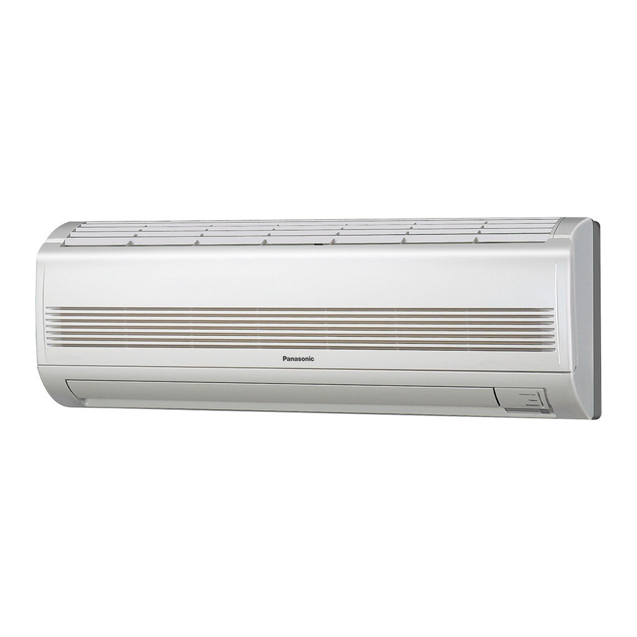
Page 49: Names Of Parts
NAMES OF PARTS Air Intakes INDOOR UNIT Air Outlet Remote Controller Drain Hose Refrigerant Tubes OUTDOOR UNIT Air Outlet This illustration is based on the external view of a standard model. NOTE Consequently, the shape may differ from that of the air conditioner which you have selected. - Page 50 UNIT DISPLAY AND OPERATION BUTTON INDOOR UNIT IMPORTANT OPERATION lamp TIMER lamp Avoid using radio equipment QUIET lamp QUIET such as mobile phone near (within 4 ft. (1.2m)) the remote control receiver. Some radio OPERATION button equipment may cause malfunction of the unit. If the trouble happens, disconnect power and restart REMOTE CONTROL receiver...
- Page 51 REMOTE CONTROLLER (DISPLAY) Displayed when transmitting data Displayed when indoor unit sensor is in use Displayed when setting temperature Displayed when temperature is shown Displayed when setting timer Displayed when the time display is set to 12-hour time. Symbols (1) Operation mode (4) Timer 24-hour clock with ON/OFF AUTO .........
-
Page 52: Remote Controller
REMOTE CONTROLLER Transmitter Sensor (Cover closed) Display ON/OFF operation button QUIET button 1 HR. TIMER button Temperature setting buttons (TEMP.) MODE selector button FAN SPEED selector button NIGHT SETBACK button FLAP button HIGH POWER button ON TIME OFF TIME Advance button Advance button setting setting... - Page 53 REMOTE CONTROLLER (CONTINUED) MODE selector button Use this button to select AUTO, HEAT, DRY or COOL mode. (AUTO) : The air conditioner calculates the difference between the thermostat setting and room temperature, and automatically selects ‘‘COOL’’ or ‘‘HEAT’’ mode as appropriate. (HEAT) : The air conditioner makes the room warmer.
-
Page 54: Using The Remote Controller
REMOTE CONTROLLER (CONTINUED) Temperature Display Selector This switches the temperature display between °C and °F. button Time Display Selector button This switches the time display between 24-hour time and 12-hour time. ACL button (ALL CLEAR) Puts the remote controller into pre-operation status. Always press this button after replacing the batteries. - Page 55 USING THE REMOTE CONTROLLER (CONTINUED) How to Use the Remote When using the remote controller, always point the unit’s transmitter head directly Controller at the air conditioner’s receiver. Air Conditioner (Indoor unit) Receiver Remote Controller (Transmitter head) Remote Controller Installation The remote controller may be operated either from a non-fixed position or from a Position wall-mounted position.
-
Page 56: Operation With The Remote Controller
OPERATION WITH THE REMOTE CONTROLLER 1. Automatic Operation The air conditioner calculates the difference between the thermostat setting and room temperature, and automatically determines the mode to operate under cooling or heating. Then, the air conditioner continuously operates under the mode selected at initial operation. -
Page 57: Manual Operation
OPERATION WITH THE REMOTE CONTROLLER (CONTINUED) 2. Manual Operation STEP 2 STEP 3 STEP 1 STEP 4 STEP 5 Check that the circuit breaker on the power panel is turned on. NOTE If the automatic operation settings of the unit do not meet your needs, press the setting buttons as described below and change the settings as desired. -
Page 58: Adjusting The Fan Speed
OPERATION WITH THE REMOTE CONTROLLER (CONTINUED) • Choose the best position in the room for the remote controller, which also acts NOTE as the sensor for room comfort and transmits the operating instructions. Once you’ve found this best position, always keep the remote controller there. •... -
Page 59: Night Setback Mode
OPERATION WITH THE REMOTE CONTROLLER (CONTINUED) 4. Night Setback Mode Night Setback Mode is used for saving energy. Press the NIGHT SETBACK button while unit is operating. mark appears in the display. To release the night setback function, press the NIGHT SETBACK button again. NOTE Pressing the MODE selector button cancels Night Setback mode. -
Page 60: Quiet Mode
OPERATION WITH THE REMOTE CONTROLLER (CONTINUED) 5. QUIET Mode QUIET Mode is used to reduce the fan sound of the indoor unit. Press the QUIET button. mark appears in the display. To cancel, press QUIET button again. • In QUIET Mode, the fan rotates at a slower speed than the fan speed setting. •... -
Page 61: Special Remarks
SPECIAL REMARKS ‘‘DRY’’ ( ) Operation How it works? • Once the room temperature reaches the level that was set, the unit’s operation frequency is changed automatically. • During DRY operation, the fan speed automatically runs at lower speed for providing a comfortable breeze. -
Page 62: Setting The Timer
SETTING THE TIMER In the descriptions below, the following settings are used for the temperature and NOTE time indicator selector button on the bottom front section of the remote controller. • Temperature: °F • Time: AM, PM 1. How to set the present (Example) To set to 10:30 pm. - Page 63 SETTING THE TIMER (CONTINUED) 3. How to set the ON time (Example) To start operation at 7:10 am. Operation Indication 1. Press the ON TIME setting The timer indication is button once. displayed, and the present ON time is shown. 2.
-
Page 64: Using The 1-Hour Off Timer
USING THE 1-HOUR OFF TIMER 1. 1-Hour OFF Timer This function causes the unit to operate for one hour and then stop, regardless of whether the unit is on or off when this button is pressed. indicator in the display indicates that this function is operating. Setting procedure: Regardless of whether the unit is operating or stopped, press the 1 HR. -
Page 65: Adjusting The Airflow Direction
ADJUSTING THE AIRFLOW DIRECTION 1. Horizontal The horizontal airflow can be adjusted by moving the vertical vanes with your hands to the left or right. When the humidity is high, the vertical vanes should be in the front CAUTION position during the cooling or dehumidifying operation. If the vertical vanes are positioned all of the way to the right or left, condensation may begin to form around the air vent and drip down. -
Page 66: Operation Without The Remote Controller
OPERATION WITHOUT THE REMOTE CONTROLLER INDOOR UNIT If you have lost the remote controller or it has trouble, follow the steps below. When the air conditioner is not running Each time the OPERATION button is pressed, the type of operation conducted is indicated by the changing color of the OPERATION lamp. - Page 67 CARE AND CLEANING (CONTINUED) Filter The filter behind the air intake grille should be checked and cleaned at least once every two weeks. How to remove the filter 1. Grasp both ends of the air Air intake grille intake grille, and remove it by opening towards the front and pulling towards you.
-
Page 68: Wired Remote Controller
CARE AND CLEANING (CONTINUED) Cleaning the main unit • Wipe clean using a soft, dry cloth. and Remote Controller • To remove stubborn dirt, moisten a cloth in warm water no hotter than 104 °F, wring thoroughly, and then wipe. •... -
Page 69: Troubleshooting (Before Calling For Service)
TROUBLESHOOTING (BEFORE CALLING FOR SERVICE) If your air conditioner does not work properly, first check the following points before requesting service. If it still does not work properly, contact your dealer or service center. Trouble Possible Cause Remedy Air conditioner does not run at all. 1. -
Page 70: Specifications
SPECIFICATIONS Indoor Unit Model No. CS-MKE7NKU CS-MKE9NKU CS-MKE12NKU Power Source Single-phase, 208-230 V, 60 Hz 2.20 2.65 3.50 Cooling Capacity 7,500 BTU/h 9,000 11,900 2.50 3.60 4.20 Heating Capacity BTU/h 8,500 12,200 14,300 Cooling Operation (H/M/L) dB(A) Operation 33/30/27 34/31/28... - Page 72 APPENDIX B Operating Instructions CS-MKE18NKU CS-MKE24NKU (852-6-4181-218-00-2)
- Page 73 Operating Instructions Split System Air Conditioner Model No. Indoor Units Outdoor Units CS-MKE18NKU CU-3KE19NBU CS-MKE24NKU CU-4KE24NBU CU-4KE31NBU This air conditioner uses the refrigerant R410A. Before operating the unit, read these operating instructions thoroughly and keep them for future reference. 1006 Kadoma, Kadoma City, Osaka, Japan 85264181218002 CV6233187600...
-
Page 74: Features
FEATURES This air conditioner is an inverter type unit that automatically adjusts capability as appropriate. Details on these functions are provided below; refer to these descriptions when using the air conditioner. • Microprocessor Controlled Operation • Air Sweep Control The interior compartment of the remote controller contains This function moves a flap up and down in the air outlet, several features to facilitate automatic operation, easy directing air in a sweeping motion around the room and... -
Page 75: Installation Location
INSTALLATION LOCATION • We recommend that this air conditioner be installed properly by qualified installation technicians in accordance with the Installation Instructions provided with the unit. • Before installation, check that the voltage of the electric supply in your home or office is the same as the voltage shown on the nameplate. - Page 76 • To prevent possible hazards from insulation failure, the unit must be grounded. • Do not clean inside the indoor and outdoor units by users. Engage authorized dealer or specialist for cleaning. • In case of malfunction of this appliance, do not repair by yourself. Contact to the sales dealer or service dealer for a repair.
-
Page 77: Names Of Parts
NAMES OF PARTS Air Intakes INDOOR UNIT Air Outlet Remote Controller Drain Hose Refrigerant Tubes OUTDOOR UNIT Air Outlet This illustration is based on the external view of a standard model. NOTE Consequently, the shape may differ from that of the air conditioner which you have selected. - Page 78 UNIT DISPLAY AND OPERATION BUTTON INDOOR UNIT IMPORTANT OPERATION lamp TIMER lamp Avoid using radio equipment QUIET lamp QUIET such as mobile phone near (within 4 ft. (1.2 m)) the remote control receiver. Some radio OPERATION button equipment may cause malfunction of the unit.
- Page 79 REMOTE CONTROLLER (DISPLAY) Displayed when transmitting data Displayed when indoor unit sensor is in use Displayed when setting temperature Displayed when temperature is shown Displayed when setting timer Displayed when the time display is set to 12-hour time. Symbols (1) Operation mode (4) Timer 24-hour clock with ON/OFF AUTO .........
- Page 80 REMOTE CONTROLLER Sensor Transmitter (Cover closed) Display ON/OFF operation button QUIET button 1 HR. TIMER button Temperature setting buttons (TEMP.) MODE selector button FAN SPEED selector button NIGHT SETBACK button FLAP button HIGH POWER button ON TIME Advance button OFF TIME Advance button setting setting...
- Page 81 REMOTE CONTROLLER (CONTINUED) MODE selector button Use this button to select AUTO, HEAT, DRY or COOL mode. (AUTO) : The air conditioner calculates the difference between the thermostat setting and room temperature, and automatically selects ‘‘COOL’’ or ‘‘HEAT’’ mode as appropriate. (HEAT) : The air conditioner makes the room warmer.
-
Page 82: Using The Remote Controller
REMOTE CONTROLLER (CONTINUED) Temperature Display Selector This switches the temperature display between °C and °F. button Time Display Selector button This switches the time display between 24-hour time and 12-hour time. ACL button (ALL CLEAR) Puts the remote controller into pre-operation status. Always press this button after replacing the batteries. - Page 83 USING THE REMOTE CONTROLLER (CONTINUED) How to Use the Remote When using the remote controller, always point the unit’s transmitter head directly Controller at the air conditioner’s receiver. Air Conditioner (Indoor unit) Receiver Remote Controller (Transmitter head) Remote Controller Installation The remote controller may be operated either from a non-fixed position or from a Position wall-mounted position.
-
Page 84: Operation With The Remote Controller
OPERATION WITH THE REMOTE CONTROLLER 1. Automatic Operation The air conditioner calculates the difference between the thermostat setting and room temperature, and automatically determines the mode to operate under cooling or heating. Then, the air conditioner continuously operates under the mode selected at initial operation. -
Page 85: Manual Operation
OPERATION WITH THE REMOTE CONTROLLER (CONTINUED) 2. Manual Operation STEP 2 STEP 3 STEP 1 STEP 4 STEP 5 Check that the circuit breaker on the power panel is turned on. NOTE If the automatic operation settings of the unit do not meet your needs, press the setting buttons as described below and change the settings as desired. -
Page 86: Adjusting The Fan Speed
OPERATION WITH THE REMOTE CONTROLLER (CONTINUED) • Choose the best position in the room for the remote controller, which also acts NOTE as the sensor for room comfort and transmits the operating instructions. Once you’ve found this best position, always keep the remote controller there. •... -
Page 87: Night Setback Mode
OPERATION WITH THE REMOTE CONTROLLER (CONTINUED) 4. Night Setback Mode Night Setback Mode is used for saving energy. Press the NIGHT SETBACK button while unit is operating. mark appears in the display. To release the night setback function, press the NIGHT SETBACK button again. NOTE Pressing the MODE selector button cancels Night Setback mode. -
Page 88: Quiet Mode
OPERATION WITH THE REMOTE CONTROLLER (CONTINUED) 5. QUIET Mode QUIET Mode is used to reduce the fan sound of the indoor unit. Press the QUIET button. mark appears in the display. To cancel, press QUIET button again. • In QUIET Mode, the fan rotates at a slower speed than the fan speed setting. •... -
Page 89: Special Remarks
SPECIAL REMARKS ‘‘DRY’’ ( ) Operation How it works? • Once the room temperature reaches the level that was set, the unit’s operation frequency is changed automatically. • During DRY operation, the fan speed automatically runs at lower speed for providing a comfortable breeze. -
Page 90: Setting The Timer
SETTING THE TIMER In the descriptions below, the following settings are used for the temperature and NOTE time indicator selector button on the bottom front section of the remote controller. • Temperature: °F • Time: AM, PM 1. How to set the present (Example) To set to 10:30 pm. - Page 91 SETTING THE TIMER (CONTINUED) 3. How to set the ON time (Example) To start operation at 7:10 am. Operation Indication 1. Press the ON TIME setting The timer indication is button once. displayed, and the present ON time is shown. 2.
-
Page 92: Using The 1-Hour Off Timer
USING THE 1-HOUR OFF TIMER 1. 1-Hour OFF Timer This function causes the unit to operate for one hour and then stop, regardless of whether the unit is on or off when this button is pressed. indicator in the display indicates that this function is operating. Setting procedure: Regardless of whether the unit is operating or stopped, press the 1 HR. -
Page 93: Adjusting The Airflow Direction
ADJUSTING THE AIRFLOW DIRECTION 1. Horizontal The horizontal airflow can be adjusted by moving the vertical vanes with your hands to the left or right. When the humidity is high, the vertical vanes should be in the front CAUTION position during the cooling or dehumidifying operation. If the vertical vanes are positioned all of the way to the right or left, condensation may begin to form around the air vent and drip down. -
Page 94: Operation Without The Remote Controller
OPERATION WITHOUT THE REMOTE CONTROLLER INDOOR UNIT If you have lost the remote controller or it has trouble, follow the steps below. When the air conditioner is not running Each time the OPERATION button is pressed, the type of operation conducted is indicated by the changing color of the OPERATION lamp. - Page 95 CARE AND CLEANING (CONTINUED) Filter The filter behind the air intake grille should be checked and cleaned at least once every two weeks. How to remove the filter 1. Grasp both ends of the air Air intake grille intake grille, and remove it by opening towards the front and pulling towards you.
-
Page 96: Wired Remote Controller
CARE AND CLEANING (CONTINUED) Cleaning the main unit • Wipe clean using a soft, dry cloth. and remote controller • To remove stubborn dirt, moisten a cloth in warm water no hotter than 104 °F, wring thoroughly, and then wipe. •... -
Page 97: Troubleshooting (Before Calling For Service)
TROUBLESHOOTING (BEFORE CALLING FOR SERVICE) If your air conditioner does not work properly, first check the following points before requesting service. If it still does not work properly, contact your dealer or service center. Trouble Possible Cause Remedy Air conditioner does not run at all. 1. -
Page 98: Specifications
SPECIFICATIONS Indoor Unit Model No. CS-MKE18NKU CS-MKE24NKU Power Source Single-phase, 208-230 V, 60 Hz 5.15 7.10 Cooling Capacity BTU/h 17,500 24,200 6.00 8.50 Heating Capacity BTU/h 20,400 29,000 Cooling Operation dB(A) 41/38/34 44/41/38 (H/M/L) Operation Sound Heating Operation dB(A) 40/37/34 43/40/37 (H/M/L) Unit Dimensions (H×W×D) -
Page 100: Appendix C Installation Instructions
APPENDIX C INSTALLATION INSTRUCTIONS CS-MKE7NKU CS-MKE9NKU CS-MKE12NKU CS-MKE18NKU CS-MKE24NKU (852-6-4190-583-00-0) -
Page 101: Installation Instructions
1-3. Optional Copper Tubing Kit Model No. 1-4. Type of Copper Tube and Insulation Material 1-5. Additional Materials Required for Installation Indoor Unit Outdoor Unit CS-MKE7NKU CU-3KE19NBU INSTALLATION SITE SELECTION ....5 CS-MKE9NKU CU-4KE24NBU 2-1. Indoor Unit CS-MKE12NKU CU-4KE31NBU 2-2. -
Page 102: Important
IMPORTANT! When Transporting Please Read Before Starting Be careful when picking up and moving the indoor and out- door units. Get a partner to help, and bend your knees when This air conditioning system meets strict safety and operating lifting to reduce strain on your back. Sharp edges or thin alu- standards. - Page 103 the flare and union tubes before connecting them, then that no metal scraps or bits of wiring have been left inside tighten the nut with a torque wrench for a leak-free the unit being serviced. connection. Others or re-installation, and while repairing refrigeration parts. CAUTION Handle liquid refrigerant carefully as it may cause frost- bite.
-
Page 104: General
Narrow Tube Wide Tube Model Outer Dia. Thickness Outer Dia. Thickness CS-MKE7NKU 1/4" (6.35 mm) 0.0314" (0.8 mm) 3/8" (9.52 mm) 0.0314" (0.8 mm) CS-MKE9NKU 1/4" (6.35 mm) 0.0314" (0.8 mm) 3/8" (9.52 mm) 0.0314" (0.8 mm) CS-MKE12NKU 1/4"... -
Page 105: Additional Materials Required For Installation
1-5. Additional Materials Required for Installation Refrigeration (armored) tape Insulated staples or clamps for connecting wire (See local codes.) Putty Refrigeration lubricant Clamps or saddles to secure refrigerant tubing Indoor unit 2. Installation Site Selection 2-1. Indoor Unit To prevent abnormal heat generation WARNING and the possibility of fire, do not place obstacles, enclosures and... -
Page 106: Embedding The Tubing And Wiring
install the indoor unit more than 3.3' (1 m) away from any antenna or power lines or connecting wires used for tele- vision, radio, telephone, security system, or intercom. Electrical noise from any of these sources may affect operation. install in a sturdy manner to avoid increased operating noise. -
Page 107: How To Install The Indoor Unit
Fig. 8 ment of the hose outlet. (Fig. 9a or 9b) (CS-MKE7NKU, CS-MKE9NKU, CS-MKE12NKU) (3) Before making the hole, check carefully that no 2-3/4" (70 mm) studs or pipes are directly run behind the spot to be cut. -
Page 108: Install The Rear Panel On The Wall
If you are not able to line up the holes in the rear panel with the beam locations marked on the wall, (CS-MKE7NKU, CS-MKE9NKU, CS-MKE12NKU) use rawl plugs or toggle bolts to go through the holes on the panel or drill 3/16" (5 mm) dia. holes in the panel over the stud locations and then mount the rear panel. -
Page 109: Removing And Installing The Grille
Grille 3-4. Removing and Installing the Grille 3-4-1. Indoor unit types (CS-MKE7NKU, CS-MKE9NKU, CS-MKE12NKU) Basically, these models can be installed and wired without removing the grille. If access to any internal part is needed, follow the steps as given below. - Page 110 3-4-2. Indoor unit types Grille Air intake grille (CS-MKE18NKU, CS-MKE24NKU) Basically, these models can be installed and wired with- out removing the grille. If access to any internal part is needed, follow the steps as given below. How to remove the grille (1) Grasp both ends of the air intake grille, and remove Fig.
-
Page 111: Shape The Indoor Side Tubing
3-5. Shape the Indoor Side Tubing (1) Arrangement of tubing by directions Frame a) Right or left tubing Cut out the corner of the right/left frame with a hacksaw or the like. (Figs. 20 and 21) Left tubing outlet b) Right-rear or left-rear tubing In this case, the corner of the frame need not be cut. -
Page 112: Wiring Instructions For Inter-Unit Connections
3-7. Wiring Instructions for Inter-unit Connections Rear (1) Insert the inter-unit wiring (according to local codes) Wall panel into the through-the-wall PVC pipe. Run the wiring Plastic toward the indoor side allowing approx. 10" (25 cm) cover to extend from the wall face. (Fig. 24) (2) Grasp both ends of the air intake grille, and remove Wiring it by opening towards the front and pulling towards... - Page 113 Loose wiring may cause the WARNING terminal to overheat or result in unit malfunction. A fire hazard may also exist. There- fore, be sure all wiring is tightly connected. When connecting each power wire to the corresponding terminal, follow the instructions “How to connect wiring to the terminal”...
-
Page 114: Mounting
3-8. Mounting (1) To install the indoor unit, mount the indoor unit onto the 2 tabs on the upper part of the rear plate. (2) Hold down the air discharge outlet and press the lower part of the indoor unit until it clicks to securely fasten to the 2 tabs on the lower part of the rear plate. -
Page 115: Drain Hose
Left-side tubing Rear panel Hole in wall allowing sufficient length for connection. Then bend the tubing using a tube bender to make the attach- ment. (Fig. 38) Wide tube Bent part (2) Switch the drain hose and drain cap. Narrow tube Fig. - Page 116 To unmount indoor unit Press the 2 marks on the lower part of the indoor unit and unlatch the tabs. Then lift the indoor unit and unmount. (Fig. 42) 3-9. Drain Hose a) The drain hose should be slanted downward to the outdoors.
-
Page 117: How To Test Run The Air Conditioner
4. How to Test Run the Air Conditioner After turning on the power of the air conditioner, use the remote controller and follow the steps below to conduct the test run. (1) Set the remote controller in Test Run mode. (Fig. -
Page 118: Remote Controller Installation Position
5. Remote Controller Installation Position The remote controller can be operated from either a non-fixed position or a wall-mounted position. To ensure that the air conditioner operates correctly, do not install the remote controller in the following places: In direct sunlight Behind a curtain or other place where it is covered More than 26' (8 m) away from the air conditioner In the path of the air conditioner’s airstream... -
Page 119: Address Switch
6. Address Switch 6-1. Address Setting of the Remote Controller The address can be set in order to prevent interference between remote controllers when 2 indoor units are installed near each other. The address is normally set to “A.” To set a different address, it is necessary to change the address on the second remote controller. -
Page 120: Connecting A Home Automation Device
7. Connecting a Home Automation Device The HA (white) 4P terminal is located on the indoor unit PCB. If a HA device will be used, connect it to this terminal. 8. Installation Check Sheet The strength of the installation location is sufficient to support the air conditioner weight. - Page 122 DC1111-0...
Need help?
Do you have a question about the CS-MKE7NKU and is the answer not in the manual?
Questions and answers