Table of Contents
Advertisement
Quick Links
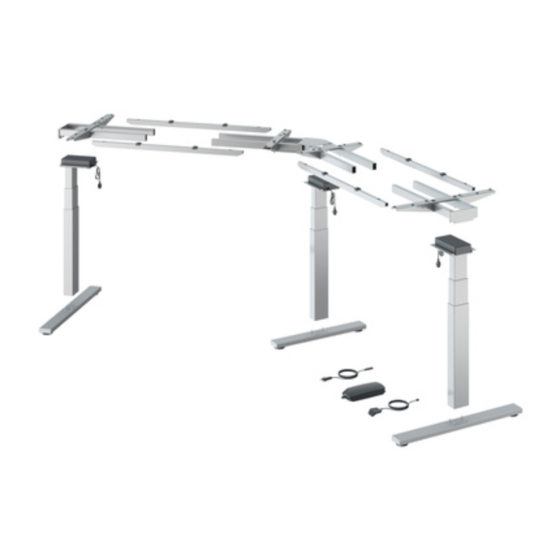
STEELFORCE PRO
SLS Highline 135° SERIES
Photo shows left side mounting. /
Abbildung zeigt linksseitige Montage. /
De foto toont de montage vanaf de zijkant./
La photo montre le montage à gauche.
Assembly Manual
Read this manual thoroughly and store in a safe place.
Montageanleitung
Bitte sorgfältig lesen und sicher aufbewahren.
Montagehandleiding
Lees deze handleiding aandachtig door en bewaar deze goed.
Manuel de montage
Veuillez lire attentivement ce manuel et le conserver dans un endroit sûr.
English
Deutsch
Nederlands
Français
Advertisement
Table of Contents

Related Manuals for Hettich Steelforce Pro SLS Highline 135 Series


Summary of Contents for Hettich Steelforce Pro SLS Highline 135 Series
- Page 1 English STEELFORCE PRO Deutsch Nederlands SLS Highline 135° SERIES Français Photo shows left side mounting. / Abbildung zeigt linksseitige Montage. / De foto toont de montage vanaf de zijkant./ La photo montre le montage à gauche. Assembly Manual Read this manual thoroughly and store in a safe place. Montageanleitung Bitte sorgfältig lesen und sicher aufbewahren.
-
Page 2: Table Of Contents
English Content GENERAL .................................6 Local value of the assembly/operating manual ......................6 Intended use ................................... 6 Improper use ................................... 6 Danger ..................................... 6 Content box ................................7-8 SAFETY INFORMATION ............................9 Symbols/Warnings ................................9 Symbols used on the workstation frame ........................9 Maximum weight allowed on frame .......................... - Page 3 Deutsch Inhaltsverzeichnis ALLGEMEINES ................................ 29 Stellenwert der Montage-/Bedienungsanleitung ....................... 29 Verwendungszweck ..............................29 Unsachgemäße Verwendung ............................. 29 Gefahr ................................... 29 Lieferumfang ................................30-31 SICHERHEITSHINWEISE ............................32 Symbol- und Hinweiserklärungen ..........................32 Verwendete Symbole am Tischgestell........................32 Zulässiges Gesamtgewicht auf dem Tischgestell ...................... 32 Zulässiges Gesamtgewicht pro Säule .........................
- Page 4 Inhoudsopgave Nederlands ALGEMEEN ................................52 Waarde van de montage- en gebruikershandleiding ....................52 Beoogd gebruik ................................52 Onjuist gebruik ................................52 Gevaar ..................................52 Inhoud verpakking ..............................53-54 VEILIGHEIDSINSTRUCTIES ............................. 55 Verklaring van symbolen en instructies ........................55 Gebruikte symbolen op het frame ..........................55 Maximaal toegestaan gewicht op het frame ......................
- Page 5 Français CONTENU GÉNÉRALITÉS ............................... 75 Valeur locale du manuel de montage/d'utilisation ....................75 Usage prévu ................................. 75 Mauvaise utilisation ..............................75 Danger ..................................75 Contenu de la boîte .............................. 76-77 INFORMATIONS RELATIVES À LA SÉCURITÉ ......................78 Symboles/avertissements ............................78 Symboles utilisés sur le cadre de poste de travail ....................
-
Page 6: General
English 1 General 1.1 Local value of the assembly/Operating Manual The guiding principle for safe use and trouble-free operation of this workstation frame is knowledge of basic safety information and regulations. This assembly/operating manual contains the most important information needed for assembling and operating the workstation frame safely. This assembly/ operating manual, in particular the safety information contained herein, must be observed by any person building the frame and working on the finished surface. -
Page 7: Content Box
1.5 Content Box English Assembly requires 2 people! Items... - Page 8 English Mounting Hardware Kit M10x35 4.5x20 M8x50 M6x16 M8x60 4.5x16 4x30 4.5x20 Tools...
-
Page 9: Safety Information
English 2 Safety Information 2.1 Symbols/Warnings The assembly/operating manual uses the following terms and signs to indicate dangers: This symbol indicates an immediate threatening situation for any person’s life or health. Failure to adhere to such information may have serious consequences for health, or could even result in life-threatening injury or death. -
Page 10: Maximum Weight Allowed Per Column
2.4 Maximum weight allowed per column English Do not exceed the maximum permitted load of 50 kg (including table top) on a col- umn. Overloading a frame may cause breakage and close by individuals may suffer serious injuries as a consequence. 50 kg 2.5 Organizational measures •... -
Page 11: In An Emergency
English 2.11 In an emergency • Stop using the workstation frame at once if you notice anything unusual (strange sounds etc.). • Have the workstation frame repaired by specialists. Refrain from using the workstation frame until it has been successfully repaired. 2.12 Maintenance and upkeep •... -
Page 12: Assembly
3 Assembly English Before attempting assembly, read the safety information in Section 2. 3.1 Checking the items supplied • Carefully open the cardboard packaging. • In doing so, do not use any long knife blades. They may damage the components inside. •... -
Page 13: Pre-Assembly Of The Crossbars For Frame Set-Up For 134 Cm And 174 Cm For Main Return And 138 Cm And 178Cm For Side Return
3.5 Pre-assembly of the Crossbars for Frame set-up for 134 cm to 174 cm for English Main Return and 138 cm to 178 cm for Side Return Recommended Top Sizes Width / size table top (Main Frame set-up Frame set-up Depth / size Table Top Thickness Return &... -
Page 14: Mounting The Feet
3.6 Mounting the Feet English Maximum Screw Torque : 10N-m 3.7 Mounting the Crossbar and Top Support Maximum Screw Torque : 12N-m... -
Page 15: Mounting The Side Return Crossbar And Top Support
3.8 Mounting the Side Return Crossbars and Top Support English Maximum Screw Torque : 12N-m... -
Page 16: Mounting The Retaining Plate 135
3.9 Mounting the Retaining Plate 135° English Maximum Screw Torque : 12N-m... -
Page 17: Mounting The Side Return Top Support
3.10 Mounting the Side Return Top Support English Maximum Screw Torque : 12N-m 3.11 Mounting the Head Cover ... -
Page 18: Mounting The Spacers
3.12 Mounting the Spacers English 3.13 Mounting the Cable Clips ... -
Page 19: Connecting The Electrical Components
3.14 Connecting the Electrical Components English 3.15 Connecting the Extension Cable Connect the Extension Cable (#F) to the motor cable for cable length extension. -
Page 20: Mounting The Table Top
3.16 Mounting the table top English 3.17 Mounting the power supply underneath the table top Keep in mind that the desk which you are assembling is height adjustable. The cables of the electrical components must be able to freely follow the movement of the desk. -
Page 21: Mounting Wire Clip
3.18 Mounting wire clip English Bond loss cable together with cable tie. Mount the wire clips for cable. Place wire into each wire clip. 3.19 Clearance around the wall or moving parts 25mm of the table top 25mm 25mm Allow a minimum clearance of 25mm from the edge of a table top to a wall or moving parts. -
Page 22: Frame Test Without Table Top
3.20 Frame test without table top English Please make sure that the workstation frame can move freely and correct at all times. In case you need to disconnect cables from the electrical components always be sure to disconnect power first. In case the height adjustment is not operating normally, stop using the workstation frame immediately and disconnect the power. -
Page 23: Correct Position Of Seats
4 Correct position of seats English Correct sitting posture Sitting incorrectly can lead to injuries at joints, bowstrings and muscles. In order to prevent this it is nec- essary to adjust your office chair and desk. Apart from the following advise you should always prevent an uncomfortable sitting posture. If you feel that the following advices leads you to an uncomfortable sitting posture simply adapt your needs. -
Page 24: Technical Specifications
5 Technical Specifications English Frame for Sit-Stand Workstation SLS-IM0120-3EN-DE-NL-FR-HT Assembly Manual version Year of release 2022 Production country Malaysia System 2-step Material Steel, Plastic and Aluminium Stroke (max.) 660 mm (26”) Frame load (max.) 150 kg Frame weight ± 47.5 kg Speed frame load ±... - Page 25 (* General Tolerance = ± 10 mm) English 133-203 cm (52.4“-79.9“) 114-174 cm (44.9“-68.5“) 60 cm (23.6“) 73.6 cm (29“) 62.5 cm (24.6“) Minimum Frame Height 128.5 cm (50.6“) Maximum Frame Height 66 cm (26“) Maximum Stroke 133-203 cm 52.4-79.9“) Table Top Width 1 133-203 cm 52.4-79.9“) Table Top Width 2...
-
Page 26: Operation And Indicators
6 Operation and Indicators English Observe the provisions of Section 2, Safety Information on page 7, in particular: Do not leave children unsupervised with the workstation frame. Children may be un- aware of the dangers presented by the workstation frame. They would be in serious danger of injuring themselves, possibly even with fatal consequences. -
Page 27: Customer Service
8 Customer Service English Make sure you have the workstation frame information at hand when contacting the customer service. Retailer : 9 Manufacturer Actiforce International B.V. Het Steenland 20 3751 LA Bunschoten-Spakenburg The Netherlands +31 (0)33 4600120 www.actiforce.com info.holland@actiforce.com 10 Recycling 10.1 Taking the workstation out of active duty Pull the power plug out of the electricity socket. -
Page 28: Ec-Declaration Of Conformity According To Machinery Directive 2006/42/Ec, Annex Ii A
11 EC-Declaration of Conformity according to Machinery Directive 2006/42/EC, English Annex II A We herewith confirm that the appliance as detailed below complies with the governing EU-directives (in particu- lar with those directives mentioned below) and bulk production will be manufactured accordingly. Article description: Electrical Height Adjustable Frame for Table Article number:... -
Page 29: Allgemeines
Deutsch 1 Allgemeines 1.1 Stellenwert der Montage-/Bedienungsanleitung Das Grundprinzip für den sicheren Einsatz und den störungsfreien Betrieb dieses Arbeitsstationsgestells ist die Kennt- nis der grundlegenden Sicherheitshinweise und -vorschriften. Die Montage-/Bedienungsanleitung beinhaltet die wichtigsten Informationen, die zur sicheren Montage und Bedienung des Arbeitsstationgestells benötigt werden. Diese Montage-/Bedienungsanleitung, insbesondere die darin enthaltenen Sicherheitshinweise, sind von jeder Per- son zu beachten, die das Gestell aufbaut und an der fertigen Oberfläche arbeitet. -
Page 30: Lieferumfang
1.6 Lieferumfang Deutsch Montage muss von 2 Personen durchgeführt werden! Teile... - Page 31 Montage onderdelen set Deutsch M10x35 4.5x20 M8x50 M6x16 M8x60 4.5x16 4x30 4.5x20 Werkzeuge...
-
Page 32: Sicherheitshinweise
Deutsch 2 Sicherheitshinweise 2.1 Symbol- und Hinweiserklärungen In der Betriebs- und Montageanleitung werden folgende Hinweise und Symbole für Gefährdungen verwendet: Dieses Symbol weist auf eine unmittelbar drohende Gefahr für das Leben und die Gesundheit von Personen hin. Das Nichtbeachten dieser Hinweise kann schwere gesundheitsschädliche Auswirkungen zum Beispiel lebensgefährliche Verletzungen bis hin zur Todesfolge haben. -
Page 33: Zulässiges Gesamtgewicht Pro Säule
Deutsch 2.4 Zulässiges Gesamtgewicht pro Säule Belasten Sie eine einzelne Säule mit nicht mehr als der maximal zulässigen Last von 50 kg, (inklusive Tischplatte). Eine Überlastung kann zum Zusammenbruch des Gestells führen und bei nahestehden Personen schwere Verletzungen verursachen. 50 kg 2.5 Organisatorische Maßnahmen •... -
Page 34: Besondere Gefahrenstellen
Deutsch 2.10 Besondere Gefahrenstellen • Beim Verstellen der Gestellhöhe besteht Verletzungsgefahr. Achten Sie bei der Verstellung des Tischgestells darauf, dass sich keine Personen in der Nähe des Tischgestells aufhalten. • Achten Sie bei der Aufstellung des Tischgestells auf vollständige Kollisionsfreiheit (z. B. Dachschrägen, bauliche Gegebenheiten, Rollcontainer, Papierkörbe usw.) in allen möglichen Verstellpositionen. -
Page 35: Montage
3 Montage Deutsch Bitte beachten Sie vor der Montage die Sicherheitshinweise in Abschnitt 2. 3.1 Überprüfung des Lieferumfangs Öffnen Sie die Kartonverpackung vorsichtig. • • Verwenden Sie hierzu keine langen Messerklingen. Dabei können Teile im Inneren beschädigt werden. • Überprüfen Sie, ob alle in der Liste in Abschnitt 1.6 angegebenen Teile vorhanden sind. •... -
Page 36: Vormontage Der Traverse Für Tischgestellbreite Hauptschenkel Von 134 Cm Zu 174 Cm Und Seitenschenkel Von 138 Cm Zu 178 Cm
Vormontage der Traverse für Tischgestellbreite Hauptschenkel von 134 cm Deutsch zu 174 cm und Seitenschenkel von 138 cm zu 178 cm Empfohlene Tischplattenmaße Tischplatten maße / Gestellbreite Gestellbreite Tischplatten Tischplattenstärke Breite (Hauptschenke & (Hauptschenke) (Nebenschenkel) maße / Tiefe Nebenschenkel) 153 cm 134 cm 138 cm 80 cm... -
Page 37: Montage Der Kufen
3.6 Montage der Kufen Deutsch Maximales Drehmoment : 10N-m Montage der Traverse und Plattenträger Maximales Drehmoment : 12N-m... -
Page 38: Montage Der Traversen Und Plattenträger Des Angewinkelten Teils
3.8 Montage der Traversen und Plattenträger des angewinkelten Teils Deutsch Maximales Drehmoment : 12N-m... -
Page 39: Montage Des Halteblechs 135
3.9 Montage des Halteblechs 135° Deutsch Maximales Drehmoment : 12N-m... -
Page 40: Montage Der Plattenträger Des Angewinkelten Teils
3.10 Montage der Plattenträger des angewinkelten Teils Deutsch Maximales Drehmoment : 12N-m 3.11 Montage der Blende ... -
Page 41: Montage Des Abstandhalters
Deutsch 3.12 Montage des Abstandhalters 3.13 Montage der Kabelhalterungen ... -
Page 42: Anschließen Der Elektrischen Bauteile
3.14 Anschließen der elektrischen Bauteile Deutsch 3.15 Verbinden des Verlängerungskabels Schließen Sie das Verlängerungskabel (#F) an das Motorkabel an, um die Kabellänge zu erweitern. -
Page 43: Montage Der Tischplatte
3.16 Montage der Tischplatte Deutsch 3.17 Montage der Steuerung unter der Tischplatte Beachten Sie, dass der Schreibtisch, den Sie montieren, höhenverstellbar ist. Die Kabel der elektrischen Bauteile müssen der Bewegung des Schreibtisches ungestört folgen können. Total 4x/6x Total 8x Total 8x Total 20x... -
Page 44: Montage Der Kabelclip
3.18 Montage Kabelclip Deutsch Lose kabel mit kabelbinder verbinden. Montieren Sie die Kabelclips. Legen Sie das Kabel durch die einzelnen Kabelclips 3.19 Sicherheitsabstand zur Wand oder beweglichen Teilen von 25 mm um die Tischplatte 25mm 25mm Lassen Sie einen Sicherheitsabstand von 25 mm zwischen der Kante der Tischplatte und Wänden bzw. -
Page 45: Funktionstest Ohne Tischplatte
3.20 Funktionstest ohne Tischplatte Deutsch Please make sure that the workstation frame can move freely and correct at all times. In case you need to disconnect cables from the electrical components always be sure to disconnect power first. In case the height adjustment is not operating normally, stop using the workstation frame immediately and disconnect the power. -
Page 46: Ergonomische Sitzeinstellung
Deutsch 4 Ergonomische Sitzeinstellung Richtige Sitzhaltung Falsches Sitzen kann zu Gelenk- und Sehnenschäden sowie Muskelschmerzen führen. Um dies zu vermeiden, müssen der Bürostuhl und der Schreibtisch richtig eingestellt werden. Zusätzlich zu den folgenden Empfehlungen sollten Sie unbequeme Sitzhaltungen stets vermeiden. Wenn Sie das Gefühl haben, dass die folgenden Empfehlungen bei Ihnen zu einer unangenehmen Sitzhaltung führen, passen Sie diese einfach an Ihre Bedürfnisse an. -
Page 47: Technische Daten
5 Technische Daten Deutsch Tischgestell für Sitz-/Steharbeitsplatz Version der Montageanleitung SLS-IM0120-3EN-DE-NL-FR-HT Veröffentlichungsjahr der Anleitung 2022 Ursprungsland Malaysia System 2-step Material Steel, Plastic and Aluminium Hub (max.) 660mm (26”) Gestellbelastung (max.) 150 kg ± 47.5 kg Gestellgewicht Geschwindigkeit mit Last ± 39 mm/s Eingangsleistung ControlForce 3 100-240Vac, 50/60Hz, 5A max... - Page 48 Allg. Toleranz = ± 10 mm) Deutsch 133-203 cm (52.4“-79.9“) 114-174 cm (44.9“-68.5“) 60 cm (23.6“) 73.6 cm (29“) 62.5 cm (24.6“) Minimale Gestellhöhe 128.5 cm (50.6“) Maximale Gestellhöhe 66 cm (26“) Maximaler Hub 133-203 cm 52.4-79.9“) Breite Tischplatte 1 133-203 cm 52.4-79.9“) Breite Tischplatte 2 73.6 cm (29“)
-
Page 49: Betriebshinweise
Deutsch 6 Betriebshinweise Beachten Sie die Bestimmungen im Abschnitt 2 Sicheheitshinweise auf Seite 24, insbesondere: Lassen Sie keine Kinder unbeaufsichtigt mit dem Tischgestell. Kinder können die von diesem Tischgestell ausgehenden Gefahren nicht einschätzen. Kinder können sich erheblich verletzen, bis hin zur Todesfolge. Weitere Vorkehrungen als Schutzmaßnah- me gegen die Benutzung durch Kinder sind nicht erforderlich. -
Page 50: Kundendienst
8 Kundendienst Deutsch Bei Inanspruchnahme des Kundendienstes bitte stets den Tischgestelltyp angeben. Händler : 9 Hersteller Actiforce International B.V. Het Steenland 20 3751 LA Bunschoten-Spakenburg The Netherlands +31 (0)33 4600120 www.actiforce.com info.holland@actiforce.com 10 Entsorgung 10.1 Außerbetriebnahme des Tischgestells • Ziehen Sie den Netzstecker aus der Steckdose. 10.2 Tischgestell abbauen und ggf. -
Page 51: Eg-Konformitätserklärung Nach Maschinenrichtlinie 2006/42/Eg, Anhang Ii A
11 EG-Konformitätserklärung nach Maschinenrichtlinie 2006/42/EG, Anhang II A Deutsch Hiermit erklären wir, dass das nachfolgend bezeichnete Gerät den einschlägigen EG-Richtlinien (insbesondere den unten benannten) entspricht und die Serie entsprechend gefertigt wird. Artikelbezeichnung: Electrical Height Adjustable Frame for Table Artikelnummer: SLS74d16*249** Das erste Symbol "*"... -
Page 52: Algemeen
Nederlands Nederlands 1 Algemeen Waarde van de montage- en gebruikershandleiding Kennis van de basisveiligheidsinformatie en de voorschriften zijn de leidraad voor een veilige en probleemloze toepassing van deze werktafel. Deze montage- en gebruikershandleiding bevat de belangrijkste informatie die nodig is voor het veilig monteren en gebruiken van het tafelframe. Deze montage- en gebruikershandleiding, en in het bijzonder de veiligheidsinformatie, moet als leidraad dienen voor de persoon die het frame gaat monteren en in gebruik gaat nemen. -
Page 53: Inhoud Verpakking
1.6 Inhoud verpakking Nederlands Monteer het frame met twee personen. Onderdelen... - Page 54 Montage onderdelen set Nederlands M10x35 4.5x20 M8x50 M6x16 M8x60 4.5x16 4x30 4.5x20 Gereedschap...
-
Page 55: Veiligheidsinstructies
2 Veiligheidsinstructies Nederlands 2.1 Verklaring van symbolen en instructies In deze handleiding worden de volgende aanduidingen en symbolen voor gevaren gebruikt: Dit symbool betekent een rechtstreeks dreigend gevaar voor leven en gezondheid van personen. Het niet in acht nemen van deze instructies kan ernstige schade aan de gezondheid toebrengen en zelfs levensgevaarlijk lichamelijk letsel of de dood tot gevolg hebben. -
Page 56: Maximaal Toegestaan Gewicht Per Kolom
2.4 Maximaal toegestaan gewicht per kolom Nederlands De maximale toegestane belasting van 50 kg (inclusief tafelblad) op een kolom niet overschrijden. Overbelasting van een frame kan schade veroorzaken en personen in de nabije omgeving kunnen als gevolg hiervan ernstige verwondingen oplopen. 50 kg 2.5 Organisatorische maatregelen •... -
Page 57: Instructies Voor Noodgevallen
Nederlands 2.11 Instructies voor noodgevallen • Stel het frame onmiddellijk buiten bedrijf wanneer er zich iets ongebruikelijks bij het frame voor- doet (vreemde geluiden etc.). • Laat het frame door een gespecialiseerd bedrijf repareren. Neem het frame pas weer in gebruik nadat het gerepareerd is. -
Page 58: Montage
3 Montage Nederlands Let vóór iedere montage op de veiligheidsinstructies van hoofdstuk 2. 3.1 Controleren op volledigheid van levering • Maak de kartonnen verpakking voorzichtig open. • Gebruik hiervoor geen lange messen. Deze kunnen de onderdelen in de verpakking beschadigen. •... -
Page 59: Voormontage Van De Dwarsbalken Voor Frame-Opstelling Van 134 Cm Om 174 Cm Voor De Hoofdpoten En 138 Cm Om 178 Cm Voor De Zijpoten
Voormontage van de dwarsbalken voor frame-opstelling van 134 cm om Nederlands 174 cm voor de hoofdpoten en 138 cm om 178 cm voor de zijpoten Aanbevolen werkbladen Werkblad breedte Frame-breedte Frame-breedte Werkblad diepte werkblad dikte (Hoofdeenheid & (Hoofdeenheid) Zij-eenheid Zij-eenheid 153 cm 134 cm 138 cm... -
Page 60: Montage Van De Voeten
3.6 Montage van de voeten Nederlands Maximale Schroefkoppel : 10N-m 3.7 Montage van de crossbar en bladdrager Maximale Schroefkoppel : 12N-m... -
Page 61: Montage Van De Zij -Unit Crossbars En Bladdragers
3.8 Montage van de zij –unit Crossbars en bladdragers Nederlands Maximale Schroefkoppel : 12N-m... -
Page 62: Monteren Van De Vasthoudplaat 135
3.9 Monteren van de vasthoudplaat 135° Nederlands Maximale Schroefkoppel : 12N-m... -
Page 63: Montage Van De Zij-Unit Bladdragers
3.10 Montage van de zij-unit bladdragers Nederlands Maximale Schroefkoppel : 12N-m 3.11 Montage van de afdekkap ... -
Page 64: Montage Van De Afstandhouders
3.12 Montage van de afstandhouders Nederlands 3.13 Montage van de kabelbinders ... -
Page 65: Aansluiten Van De Elektrische Componenten
3.14 Aansluiten van de elektrische componenten Nederlands 3.15 Het aansluiten van de verlengkabel Sluit de verlengkabel (# F) aan op de motorkabel voor een verlenging van de kabellengte. -
Page 66: Montage Van Het Werkblad
3.16 Montage van het werkblad Nederlands 3.17 Montage van de handbediening Het is essentieel dat uw frame in hoogte verstelbaar is. De kabels van de elektrische componenten mogen tijdens een hoogteverstelling niet belemmerd worden. Let er hierbij op dat de maximale hoogteverstelling altijd mogelijk moet zijn! Total 4x/6x Total 8x Total 8x... -
Page 67: Montage Van De Kabelclips
3.18 Montage van de kabelclips Nederlands Bind de losse kabels samen met de kabelbinders. Monteer de kabelclip. Plaas de kabel in de kabelclip. 3.19 Afstand van 25 mm tussen de muur of andere objecten en het werkblad 25mm 25mm Houd een minimum van 25 mm afstand tussen het werkblad en de muur of andere objecten. -
Page 68: Frame Test Zonder Werklad
3.20 Frame test zonder werklad Nederlands Let erop dat het frame te allen tijde correct en vrij kan bewegen Indien de kabel van de elektrische componenten moet worden losgekoppeld, dient u eerst de stroomtoevoer los te koppelen. Indien het frame niet naar behoren werkt, stop dan direct met werken aan het frame. -
Page 69: Correcte Zitpositie
Nederlands 4 Correcte zitpositie Correcte houding Een onjuiste houding kan schade aan gewrichten, pezen en spierpijn veroorzaken. Om dit te voorko- men, moet de bureaustoel en het bureau goed worden afgesteld. In aanvulling op de volgende aanbevelingen, moet een oncomfortabele zithouding worden voorkomen. Indien een van de vol- gende aanbevelingen leidt naar een voor u oncomfortabele houding, pas de bureaustoel en het bureau dan aan naar uw behoeften. -
Page 70: Technische Specificaties
5 Technische specificaties Nederlands Frame voor een elektrisch in hoogte verstelbaar zit/sta frame Handleiding versie SLS-IM0120-3EN-DE-NL-FR-HT Jaar van uitgave 2022 Land van productie Maleisië Systeem Tweetraps Materiaal Staal, plastic en aluminium Slag (maximaal) 660 mm (26”) Frame belasting (maximaal) 150 kg Frame gewicht ±... - Page 71 (* Gemiddelde tolerantie = ± 10 mm) Nederlands 133-203 cm (52.4“-79.9“) 114-174 cm (44.9“-68.5“) 60 cm (23.6“) 73.6 cm (29“) 62.5 cm (24.6“) Minimale frame hoogte 128.5 cm (50.6“) Maximale frame hoogte 66 cm (26“) Maximale slag 133-203 cm 52.4-79.9“) Tafel breedte 1 133-203 cm 52.4-79.9“) Tafel breedte 2...
-
Page 72: Bediening En Gebruiksaanwijzingen
Nederlands 6 Bediening en Gebruiksaanwijzingen Laat kinderen niet zonder toezicht het frame gebruiken. Kinderen zijn niet in staat de gevaren van het frame in te schatten. Ze lopen hierdoor groot risico op ernstig letsel, mogelijk zelfs met fatale gevolgen. Zorg er in ieder geval voor dat het frame niet verder versteld kan worden indien het toch door kinderen wordt gebruikt. -
Page 73: Klantenservice
Nederlands 8 Klantenservice Houd de gegevens van het frame bij de hand wanneer u contact opneemt met uw dealer. Dealer: 9 Fabrikant Actiforce International B.V. Het Steenland 20 3751 LA Bunschoten-Spakenburg The Netherlands +31 (0)33 4600120 www.actiforce.com info.holland@actiforce.com 10 Recycling 10.1 Buitenbedrijfstelling van het frame •... -
Page 74: Eu-Verklaring Van Overeenstemming Volgens Machinerichtlijn 2006/42/Eg, Bijlage Ii A
11 EU-Verklaring van overeenstemming volgens machinerichtlijn 2006/42/EG, Nederlands bijlage II A Hierbij verklaren wij dat het artikel dat hieronder wordt beschreven, voldoet aan de relevante EU-richtlijnen (in het bijzonder de hieronder vermelde) en dat de serie dienovereenkomstig is vervaardigd. Artikelomschrijving: Electrical Height Adjustable Frame for Table Artikelnummer: SLS74d16*249**... -
Page 75: Généralités
Français 1 Généralités 1.1 Valeur locale du manuel de montage/d'utilisation Le principe directeur pour une utilisation sûre et un fonctionnement sans problème de ce cadre de poste de travail est la connaissance des informations et des règles de sécurité de base. Ce manuel de montage/d'utilisation contient les principales informations pour assembler et utiliser le cadre de poste de travail en toute sécurité. -
Page 76: Contenu De La Boîte
Français 1.5 Contenu de la boîte Le montage nécessite la pré- sence de 2 personnes ! Articles... - Page 77 Français Kit de matériel de montage M10x35 4.5x20 M8x50 M6x16 M8x60 4.5x16 4x30 4.5x20 Outils...
-
Page 78: Informations Relatives À La Sécurité
Français 2 Informations relatives à la sécurité Symboles/Avertissements Le manuel de montage/d’utilisation utilise les termes et les pictogrammes suivants pour indiquer des dangers Ce symbole indique une situation de menace immédiate pour la vie ou la santé d'une per- sonne. Le non-respect de ces informations peut avoir de graves conséquences pour la santé, voire entraîner des blessures potentiellement mortelles. -
Page 79: Poids Maximum Autorisé Par Colonne
Français 2.4 Poids maximum autorisé par colonne Ne dépassez pas la charge maximale autorisée de 50 kg (plateau compris) sur une colonne. La surcharge d'un cadre peut provoquer une rupture et les per- sonnes à proximité peuvent en subir de graves blessures. 50 kg 2.5 Mesures d’organisation •... -
Page 80: Dangers Spécifiques
Français 2.10 Dangers spécifiques • Le réglage de la hauteur du cadre peut entraîner un risque de blessure. Assurez-vous qu’il n'y a per- sonne d'autre dans les environs immédiats du cadre. • Lors du montage du cadre de poste de travail, veillez à ce qu'il y ait suffisamment d'espace pour évi- ter les accidents (inclinaison du toit, objets fixes, armoires de classement, poubelles, etc.) dans toutes les directions possibles. -
Page 81: Montage
3 Montage Français Avant de tenter le montage, lisez les informations relatives à la sécurité de la section 2. 3.1 Contrôle des articles fournis • Ouvrez soigneusement l'emballage en carton. • Pour ce faire, n'utilisez pas de longues lames de couteau. Elles peuvent endommager les compo- sants qui se trouvent à... -
Page 82: Principal Et 138 Cm Et 178 Cm Pour Le Retour Latéral
3.5 Prémontage des barres transversales pour la mise en place du cadre pour Français 134 cm à 174 cm pour le retour principal et 138 cm à 178 cm pour le retour latéral Dimensions supérieures recommandées Largeur / dimension de Mise en place du Mise en place Profondeur /... -
Page 83: Montage Des Pieds
3.6 Montage des pieds Français couple de serrage maximal : 10N-m 3.7 Montage de la barre transversale et du support supérieur couple de serrage maximal : 12N-m... -
Page 84: Montage De La Barre Transversale De Retour Latéral Et Du Support Supérieur
Français 3.8 Montage des barres transversales de retour latéral et du support supérieur couple de serrage maximal : 12N-m... -
Page 85: Montage De La Plaque De Retenue 135
3.9 Montage de la plaque de retenue 135° Français couple de serrage maximal : 12N-m... -
Page 86: Montage Du Support Supérieur De Retour Latéral
3.10 Montage du support supérieur de retour latéral Français couple de serrage maximal : 12N-m 3.11 Montage du couvercle ... -
Page 87: Montage Des Espaceurs
3.12 Montage des espaceurs Français 3.13 Montage des clips de câble ... -
Page 88: Connexion Des Composants Électriques
3.14 Connexion des composants électriques Français 3.15 Connexion du câble d’extension Connexion du câble d’extension (#F) au câble de moteur pour le câble d’extension en longueur. -
Page 89: Montage Du Plateau
Français 3.16 Montage du plateau 3.17 Montage de l’alimentation électrique sous le plateau N'oubliez pas que le bureau que vous assemblez est réglable en hau- teur. Les câbles des composants électriques doivent pouvoir suivre libre- ment le mouvement du bureau. Total 4x/6x Total 8x Total 8x... -
Page 90: Montage Du Clips De Câble
3.18 Montage du clips de câble Français Reliez les câbles libres avec une attache de câble. Montez les clips pour le câble. Placez le câble dans chaque clips de câble. 3.19 Espace autour du mur et des pièces mobiles à 25 mm du plateau ... -
Page 91: Essai Du Cadre Sans Plateau
3.20 Essai du cadre sans plateau Français Veuillez vous assurer que le cadre de poste de travail se déplace toujours correcte- ment et librement. Si vous devez débrancher les câbles des composants électriques, veillez toujours à couper l'alimentation électrique au préalable. Si le réglage de la hauteur ne fonctionne pas normalement, cessez immédiate- ment d'utiliser le cadre de poste de travail et débranchez l'alimentation. -
Page 92: Position Correcte Des Sièges
Position correcte des sièges Français Position assise correcte Une mauvaise position assise peut entraîner des blessures aux articulations, aux tendons et aux muscles. Pour l’éviter, il est nécessaire de régler votre siège et votre bureau. Outre le conseil suivant, vous devez toujours éviter une position assise inconfortable. Si vous pensez que les conseils suivants vous conduisent à... -
Page 93: Spécifications Techniques
Français 5 Spécifications techniques Cadre pour poste de travail assis-debout SLS-IM0120-3EN-DE-NL-FR-HT Version du manuel de montage Année d’édition 2022 Pays de production Malaisie Système 2 étapes Matériau Acier, plastique et aluminium Course (max.) 660 mm (26”) Charge du cadre (max.) 150 kg ±... - Page 94 Français (* Tolérance générale = ± 10 mm) 133-203 cm (52.4“-79.9“) 114-174 cm (44.9“-68.5“) 60 cm (23.6“) 73.6 cm (29“) 62.5 cm (24.6“) Hauteur minimale du cadre 128.5 cm (50.6“) Hauteur maximale du cadre 66 cm (26“) Course maximale 133-203 cm 52.4-79.9“) Plateau Largeur 1 133-203 cm 52.4-79.9“) Plateau Largeur 2...
-
Page 95: Fonctionnement Et Indicateurs
6 Fonctionnement et indicateurs Français Veuillez respecter les dispositions de la section 2, Informations relatives à la sécurité, page 7, en particulier : Ne laissez pas les enfants sans surveillance avec le cadre du poste de travail. Les en- fants peuvent ignorer les dangers que présente le cadre du poste de travail. Ils ris- queraient de se blesser gravement, voire de subir des conséquences mortelles. -
Page 96: Service Clientèle
8 Service clientèle Assurez-vous d'avoir les informations sur le cadre de poste de travail à portée de main lorsque vous prenez contact avec le service clientèle. Revendeur : 9 Manufacturer Actiforce International B.V. Het Steenland 20 3751 LA Bunschoten-Spakenburg Pays-Bas +31 (0)33 4600120 www.actiforce.com 10 Recyclage... -
Page 97: 11 Déclaration De Conformité Ce Au Sens De La Directive Machine 2006/42/Ce, Annexe Ii A
11 Déclaration de conformité CE au sens de la directive machine 2006/42/CE, Français Annexe II A Nous confirmons par la présente que l'appareil tel que décrit ci-dessous est conforme aux directives euro- péennes en vigueur (en particulier aux directives mentionnées ci-dessous) et que la production en série sera réalisée en conséquence.
Need help?
Do you have a question about the Steelforce Pro SLS Highline 135 Series and is the answer not in the manual?
Questions and answers