Table of Contents
Advertisement
Available languages
Available languages
Quick Links
Betriebsanleitung .................................................. Seite 1 – 15
Operating manual ............................................... page 16 – 31
Elektronisches Digitalthermometer SolarTemp 850 / 851
Elektronisches Messsystem für örtliche Temperaturmessung (Marineausführung)
Electronic Digital Thermometer SolarTemp 850 / 851
Electronic Measuring System for Local Temperature Measurement (Marine Version)
Advertisement
Chapters
Table of Contents

Subscribe to Our Youtube Channel
Related Manuals for SIKA SolarTemp 850


Summary of Contents for SIKA SolarTemp 850
- Page 1 Betriebsanleitung ..........Seite 1 – 15 Operating manual ..........page 16 – 31 Elektronisches Digitalthermometer SolarTemp 850 / 851 Elektronisches Messsystem für örtliche Temperaturmessung (Marineausführung) Electronic Digital Thermometer SolarTemp 850 / 851 Electronic Measuring System for Local Temperature Measurement (Marine Version)
-
Page 2: Table Of Contents
Weitergabe sowie Vervielfältigung dieser Betriebsanleitung, Verwertung und Mitteilung ihres Inhalts sind verboten, soweit nicht ausdrücklich gestattet. Zuwiderhandlungen verpflichten zu Schadenersatz. Alle Rechte für den Fall der Patent-, Gebrauchsmuster- oder Geschmacksmustereintragung vorbehal- ten. - 2 - © SIKA • Ba_SolarTemp850_851 • 04/2022... -
Page 3: Hinweise Zur Betriebsanleitung
WICHTIG Nichtbeachtung kann Sach- und Umweltschäden zur Folge haben. Sollten Sie Probleme oder Fragen haben, wenden Sie sich an Ihren Lieferanten oder direkt SIKA Dr. Siebert & Kühn GmbH & Co. KG Struthweg 7–9 34260 Kaufungen / Germany +49 5605 803-0 ... -
Page 4: Sicherheitshinweise
Lesen Sie die Betriebsanleitung sorgfältig durch. Befolgen Sie alle Anweisungen und Hin- weise, um Personen- oder Sachschäden zu vermeiden. Bestimmungsgemäße Verwendung Das elektronische Digitalthermometer SolarTemp 850 / 851 ist ein örtlich anzeigendes Tem- peraturmessgerät und darf nur zur Messung (-60…650 °C) und Anzeige von Temperaturen flüssiger und gasförmiger Medien benutzt werden. -
Page 5: Gerätebeschreibung
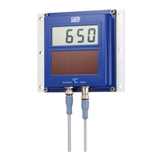
SolarTemp 850 / 851 Gerätebeschreibung Gerätebeschreibung Das elektronische Digitalthermometer SolarTemp 850 / 851 ist ein örtlich anzeigendes Tem- peraturmessgerät für Pt1000-Temperaturfühler. Das SolarTemp 850 verfügt über eine einge- baute Solarzelle, die das Gerät mit Energie versorgt. Es arbeitet zuverlässig bei Beleuchtun- gen mit Kunstlicht ab 80 Lux. -
Page 6: Aufbau
Befestigungsplatte. Einbau Das SolarTemp 850 / 851 kann getrennt von der Messstelle an einem gut sichtbaren und leicht zugänglichen Ort montiert werden. Es arbeitet unabhängig von seiner Einbaulage. Die LCD-Digitalanzeige ist auf einen sogenannten 6 Uhr Blickwinkel optimiert. Sie erreicht den höchsten Anzeigekontrast bei der Betrachtung von leicht vorn unten. -
Page 7: Montagebeispiel Eines Abgassensors
SolarTemp 850 / 851 Einbau 4.2 Montagebeispiel eines Abgassensors Die nachfolgenden Arbeitsschritte beziehen Sie auf den in diesem Beispiel verwendeten Typ von Temperaturfühler. Beachten Sie die Einbauhinweise in der Betriebsanleitung des ver- wendeten Temperaturfühlers. Einbauhinweise Temperaturfühler Die Messgenauigkeit kann durch die Einbauverhältnisse maßgeblich beeinflusst werden, z. - Page 8 Achten Sie auf den richtigen Sitz des Temperatur- fühlers im Tauchrohr. 5. Ausrichten. 6. Überwurfmutter festziehen. Richten Sie den Temperaturfühler so aus, dass die Leitung zum ersten Befestigungspunkt zeigt ( S. 11). - 8 - © SIKA • Ba_SolarTemp850_851 • 04/2022...
-
Page 9: Elektrischer Anschluss
Ziehen Sie die Rändelmutter des Steckers mit einem Anzugsmoment von max. 1 Nm fest. Beschaltung Das SolarTemp 850 / 851 wird als lokales Anzeigegerät mit einem einfachen Temperaturfüh- ler (1x Pt1000 / 2-Leiter / Klasse B) beschaltet. Bei Verwendung des Transmitterausganges ist ein doppelter Temperaturfühler (2x Pt1000 / 2-Leiter / Klasse B) erforderlich. -
Page 10: Transmitter
Der Transmitterausganges ist verpolungssicher, so dass beim Vertauschen der Anschlüsse kein Schaden an dem Gerät entstehen kann. Pinbelegung: Pin 1: GND/Sig- (braun) Pin 3: +UB/Sig+ (blau) SIKA Anschlussleitung: Hinweis: Die Farbangaben beziehen sich auf Anschlussleitungen von SIKA. - 10 - © SIKA • Ba_SolarTemp850_851 • 04/2022... -
Page 11: Hinweise Zum Verlegen Der Anschlussleitung
SolarTemp 850 / 851 Elektrischer Anschluss 5.3 Hinweise zum Verlegen der Anschlussleitung Für das SolarTemp 850 / 851 gibt es von SIKA spezielle, sehr robuste Anschlussleitungen aus FEP. Sie sind für den dauerhaften Einsatz bei Temperaturen bis zu 200 °C ausgelegt. WICHTIG Werden die Grenzwerte der Anschlussleitung überschritten, kann es zu Material-... -
Page 12: Messbetrieb
Messbetrieb SolarTemp 850 / 851 Messbetrieb Das SolarTemp 850 hat keinen Schalter. Wenn genügend Licht, mindestens 80 Lux, auf die Solarzelle trifft, schaltet es sich automatisch ein. Das SolarTemp 851 hat keinen Schalter. Sobald die Versorgungsspannung (15…26 VDC) aktiv ist oder genügend Licht, mindestens 80 Lux, auf die Solarzelle trifft, schaltet es sich au- tomatisch ein. -
Page 13: Fehlerbehebung
Sie den Befestigungsort und prüfen Sie, ob das Stromsignal bzw. die Versorgungsspan- nung angeschlossen sind. Wenn Sie einen Fehler nicht beheben können, kontaktieren Sie bitte SIKA. WICHTIG Bitte beachten Sie die Hinweise zum Ablauf des Rücksendeverfahrens auf unse- rer Website (www.sika.net/service/service/rma-warenruecksendung). -
Page 14: Demontage Und Entsorgung
Hausmüll entsorgt werden. Führen Sie das Gerät der lokalen Wiederverwertung zu oder schicken Sie das Gerät an Ihren Lieferanten bzw. SIKA zurück. * WEEE-Reg.-Nr.: DE 25976360 Schutzrohre Bei Anwendungen mit besonderen Belastungen muss ein zusätzliches Schutzrohr, nach DIN 43772:2000, verwendet werden. -
Page 15: Abmessungen Befestigung
SolarTemp 850 / 851 Abmessungen Befestigung 10 Abmessungen Befestigung 11 Zulassungen EU RO Mutual Recognition Type Approval Certificate (SolarTemp 851 ausstehend) (Beinhaltet: ABS, BV, CCS, CRS, DNV, IRS, KR, LR, ClassNK, PRS, RINA, RS) Technische Änderungen vorbehalten - 15 -... - Page 16 Offenders will be held liable for the payment of damages. All rights reserved in the event of the grant of a patent, utility model or design. - 16 - © SIKA • Ba_SolarTemp850_851 • 04/2022...
-
Page 17: About This Operating Manual
Failure to do so may result in damage to property and the environment. If you have any problems or questions, please contact your supplier or contact us directly at: SIKA Dr. Siebert & Kühn GmbH & Co. KG Struthweg 7–9 34260 Kaufungen / Germany ... -
Page 18: Safety Instructions
(-60...650 °C) and indicating tempera- tures of liquid and gaseous media. WARNING The digital thermometer of the type SolarTemp 850 / 851 is no safety component in accordance with Directive 2006/42/EC (Machine Directive). Never use the device as a safety component. -
Page 19: Device Description
Device Description Device Description The electronic digital thermometer SolarTemp 850 / 851 is a local indicating temperature measuring device for Pt1000 temperature sensors. The SolarTemp 850 has a built-in solar cell that supplies the device with energy. It works reliably in illuminations with artificial light from 80 lux. -
Page 20: Construction
Mounting plate. Installation The SolarTemp 850 / 851 can be separately mounted from the measuring point in a visible and easily accessible location. It independently operates from its installation position. The LCD digital display has been optimised for a so-called 6 o’clock viewing angle. The high- est display contrast is achieved by viewing from the lower front. -
Page 21: Mounting Example Of An Exhaust Gas Sensor
SolarTemp 850 / 851 Installation 4.2 Mounting Example of an Exhaust Gas Sensor The following steps refer to the type of temperature sensor used in this example. For other types, individual steps may vary or are not applicable. Installation instructions temperature sensor The measuring accuracy can be significantly influenced by the installation conditions e.g. - Page 22 5. Align. 6. Fully tighten union nut. Align the temperature sensor so that the connect- ing cable is showing to the first attachment point ( p. 25). - 22 - © SIKA • Ba_SolarTemp850_851 • 04/2022...
-
Page 23: Electrical Connection
Electrical Connection 5.1 Temperature Sensor Connection Screw the plug of the temperature sensor onto the socket of the SolarTemp 850 / 851. Tighten the knurled nut of the plug with a tightening torque of max. 1 Nm. Wiring The SolarTemp 850 / 851 is used as a local display with a single temperature sensor (1x Pt1000 / 2-wire / class B). -
Page 24: Transmitter
/ electronic equipment and sys- tems Connection Screw the plug of the connection cable onto the socket on the SolarTemp 850 / 851. Tighten the knurled nut of the plug with a tightening torque of max. 1 Nm. Wiring The transmitter output is protected against polarity reversal so no damage to the device may occur if the connections are reversed. -
Page 25: Advice For Laying The Connection Cable
5.3 Advice for Laying the Connection Cable SIKA offers special, very robust connection cables made of FEP for the SolarTemp 850 / 851.They are designed for continuous use at temperatures up to 200 °C. IMPORTANT If the specified limits of the connection cable are exceeded, it can cause material damage and malfunctions. -
Page 26: Measuring
SolarTemp 850 / 851 Measuring The SolarTemp 850 has no switch. If enough light hits the solar cell, at least 80 lux, the de- vice automatically switches on. The SolarTemp 851 has no switch. As soon as the supply voltage (15...26 VDC) is active or sufficient light, at least 80 lux, hits the solar cell, it switches on automatically. -
Page 27: Troubleshooting
If you are not able to remedy an error, please contact SIKA. IMPORTANT Please note the information on the return procedure on our website (www.sika.net/en/service/service/rma-return-of-products). -
Page 28: Disassembly And Disposal
The device consists of various different materials. It must not be disposed of with household waste. Take the device to your local recycling plant send the device back to your supplier or to SIKA. * WEEE reg. no.: DE 25976360 Protective Tube If the device is to be used for high-stress applications, then an additional protective tube certi- fied according to DIN 43772:2000 is required. -
Page 29: Dimensions Mounting
SolarTemp 850 / 851 Dimensions Mounting 10 Dimensions Mounting 11 Approvals EU RO Mutual Recognition Type Approval Certificate (SolarTemp 851 pending) (Covers: ABS, BV, CCS, CRS, DNV, IRS, KR, LR, ClassNK, PRS, RINA, RS) Technical changes reserved - 29 -... - Page 30 SolarTemp 850 / 851 - 30 - © SIKA • Ba_SolarTemp850_851 • 04/2022...
- Page 31 SolarTemp 850 / 851 Technical changes reserved - 31 -...
- Page 32 SIKA Dr. Siebert & Kühn GmbH & Co. KG Struthweg 7–9 34260 Kaufungen / Germany +49 5605 803-0 +49 5605 803-555 info@sika.net www.sika.net © SIKA • Ba_SolarTemp850_851 • 04/2022...
Need help?
Do you have a question about the SolarTemp 850 and is the answer not in the manual?
Questions and answers