
Related Manuals for AERMEC FHX


Summary of Contents for AERMEC FHX
- Page 1 TECHNICAL MANUAL FAN COIL WITH GERMICIDAL LAMP UVPO ISO 9001 - Cert. n° 0128/4 IFHXTY 0809 4267320_00 Replace: 5266420_00 / 0705...
- Page 3 Pay particular attention to the operating stan- warranty. dards with “DANGER” or “WARNING” signals as failure to AERMEC S.p.A. declines all responsibility for any damage comply with them can cause damage to the machine and/or whatsoever persons or objects.
- Page 4 TRASPORTO • CARRIAGE • TRANSPORT • TRANSPORT • TRANSPORTE NON bagnare • Do NOT wet NON calpestare • Do NOT trample CRAINT l’humidité • Vor Nässe schützen NE PAS marcher sur cet emballage • Nicht betreten NO mojar NO pisar Sovrapponibilità: controllare sull’imballo la posizione della freccia per conoscere il numero di macchine impilabili.
- Page 5 WARNING! DANGER! Any use of the cedures requiring access to the internal eye and skin irritation. unit not expressly indicated by Aermec parts of the fan coil, cut off the power Lamps should be replaced every year is strictly prohibited.
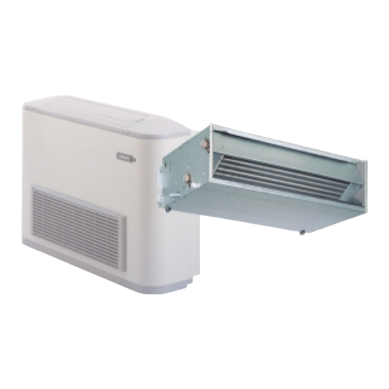
- Page 6 FHX - FAN COIL WITH GERMICIDAL LAMP Congratulations on your purchase of this Aermec FHX fan coil. Made with materials of superior quality in strict compliance with safety regulations, "FHX" is easy to use and will have a long life.
- Page 7 P and PO versions are equipped with G2 The UVC radiation emitted by the lamp flexible supports. The FHX UVPO ver- class filter. destroys the main cellular DNA and sion is equipped with a boosted motor CABINET RNA.
- Page 8 There is a wide range of accessories for or externally. Consult the characteristics speed. Performances at medium and FHX fan coils, sometimes some of them and compatibility of the control panels minimum speeds can be obtained by cannot be used at the same time; check supplied as accessories.
- Page 9 SYSTEM CONFIGURATIONS FOR FHX FAN COILS Key: Water temperature sensor Room temperature sensor Solenoid valve (Heating / Cooling) V3,V2,V1 Maximum, Medium or Minimum fan speed System with 2 pipes, without water sensor 230V 230V 230V UVGI UVGI UVGI System with 2 pipes, with water sensor...
- Page 10 TECHNICAL DATA FHX UV - UVP with a 3-row coil FHX 22 FHX 32 FHX 42 FHX 50 FHX 62 FHX 82 Mod. Heating 3400 4975 7400 8620 12920 15140 W (max.) Heating capacity W (med.) 2700 4085 6415 7530...
- Page 11 TECHNICAL DATA FHX UVPO with a 3-row coil FHX 22 FHX 32 FHX 42 FHX 50 FHX 62 FHX 82 Mod. Heating W (max.) 3400 4975 7400 8620 12920 15140 Heating capacity W (med.) 2700 4085 6415 7530 10940 13350 W (min.)
- Page 12 TECHNICAL DATA FHX UVP with a 4-row coil FHX 24 FHX 34 FHX 44 FHX 54 FHX 64 FHX 84 Mod. Heating W (max.) 3950 5850 8600 10100 14300 17100 Heating capacity W (med.) 3200 4850 6930 8760 11500 14420 W (min.)
- Page 13 TECHNICAL DATA FHX UVPO with a 4-row coil Mod. FHX 24 FHX 34 FHX 44 FHX 54 FHX 64 FHX 84 Heating W (max.) 3950 5850 8600 10100 14300 17100 Heating capacity W (med.) 3200 4850 6930 8760 11500 14420 W (min.)
- Page 14 OPERATING LIMITS Maximum water input temperature ......80 °C Maximum operating pressure ........8 bar Operating voltage ......230V(±10%) ~ 50Hz Room temperature ..........0-45°C Humidity of the air ........... <85% U.R. Output limits (3-row coil): MODEL Minimum output [l/h] Maximum output [l/h] 1100 1100...
- Page 15 COOLING CAPACITY FHX 22 TOTAL COOLING CAPACITY [W] SENSIBLE COOLING CAPACITY [W] Air temperature - wet bulb [°C] Air temperature - dry bulb [°C] Water temp. Inlet [°C] 1238 1731 2254 – – 1065 1253 1434 1590 1743 1891 1110...
- Page 16 COOLING CAPACITY FHX 32 TOTAL COOLING CAPACITY [W] SENSIBLE COOLING CAPACITY [W] Air temperature - wet bulb [°C] Air temperature - dry bulb [°C] Water temp. Inlet [°C] 1303 1866 2512 3148 – 1134 1368 1612 1817 2004 2184 1618...
- Page 17 COOLING CAPACITY FHX 42 TOTAL COOLING CAPACITY [W] SENSIBLE COOLING CAPACITY [W] Air temperature - wet bulb [°C] Air temperature - dry bulb [°C] Water temp. Inlet [°C] 2871 – – – – 2336 2730 3088 3401 3715 – 2491...
- Page 18 COOLING CAPACITY FHX 50 TOTAL COOLING CAPACITY [W] SENSIBLE COOLING CAPACITY [W] Air temperature - wet bulb [°C] Air temperature - dry bulb [°C] Water temp. Inlet [°C] 3542 – – – – 2624 2952 3296 3632 – – 3227...
- Page 19 COOLING CAPACITY FHX 62 TOTAL COOLING CAPACITY [W] SENSIBLE COOLING CAPACITY [W] Air temperature - wet bulb [°C] Air temperature - dry bulb [°C] Water temp. Inlet [°C] 4190 5511 6974 – – 3490 3981 4464 4949 5415 5861 3725...
- Page 20 COOLING CAPACITY FHX 82 TOTAL COOLING CAPACITY [W] SENSIBLE COOLING CAPACITY [W] Air temperature - wet bulb [°C] Air temperature - dry bulb [°C] Water temp. Inlet [°C] 5591 7373 – – – 4995 5671 6366 7036 7680 8303 4979...
- Page 21 HEATING CAPACITY CORRECTION FACTORS The heat yields refer to the maximum speed. For the rest of the speeds the values must be multiplied by the following factors: MODEL FHX 22 FHX 32 FHX 42 FHX 50 FHX 62 FHX 82 Medium speed 0.79 0.82...
- Page 22 HEATING CAPACITY CORRECTION FACTORS The heat yields refer to the maximum speed. For the rest of the speeds the values must be multiplied by the following factors: MODEL FHX 24 FHX 34 FHX 44 FHX 54 FHX 64 FHX 84 Medium speed 0.81 0.83...
- Page 23 P L7: min. speed version PO min. speed version P FHX 22 - 24 FHX 32 - 34 140 155 170 185 200 215 230 245 260 275 290 260 275 290 305 320 335 350 365 380 395 410 425 440 455...
- Page 24 3R COIL PRESSURE DROPS FHX 62 FHX 32 FHX 42 FHX 22 FHX 50 FHX 82 2200 800 1000 1200 1400 1600 1800 2000 Water flow rate [l/h] The pressure drops in the previous diagram refer to a medium water temperature of 10 °C. The following table shows the correc- tion to apply to the pressure drops when the medium water temperature varies.
- Page 25 C O R R E C T I O N F A C T O R S W H E N O P E R A T I N G U S I N G G L Y C O L W A T E R Key: Pressure drop...
- Page 26 50 (E) Min. 45.6 51.0 48.4 44.6 41.1 33.2 19.8 54.4 (E) = Eurovent certified performances. SOUND PRESSURE LEVEL expressed in dB (A) Speed Model FHX Max. 41.5 39.5 42.5 47.5 48.5 53.5 Med. 34.5 32.5 35.5 42.5 42.5 48.5 Min.
- Page 27 51,7 48,2 40,3 26,6 61,3 Min. 46.7 52.3 49.6 45.2 42.1 34.5 21.2 54.4 SOUND PRESSURE LEVEL expressed in dB (A) Speed Model FHX Max. 42.5 39.5 46.5 47.5 48.5 52.5 Medium 37.5 32.5 41.5 44.5 42.5 48.5 Min. 26.5 27.5...
- Page 28 SOUND POWER LEVEL FOR DUCTED WALL/CEILING-MOUNTING FHX-PO MODELS expressed in dB The level of the sound power emitted by the fan coils (FHX-PO) The following diagrams make it possible to determine the level installed in ducts depends not only on the fan speed, but also...
- Page 29 Made of galvanised sheet metal, it is cabinet. STAT used to channel the intake air when the The BC5 tray is installed on FHX 22, 32, unit is vertically or horizontally flush- Multifunction electronic room thermo- 42, 50 and 24, 34, 44, 54 with horizon- mounted.
- Page 30 The SE accessories have to be installed in combination with ZX feet. (*) BC8 and BC9 cannot be applied to fan coils with a protective cabi- (***) The 4-row coil models can be combined only with VCF42 net. (FHX 24-34-44-54) and VCF43 (FHX 64-84) valves.
- Page 31 ACCESSORIES PANELS / FAN COILS COUPLING Models FHX - UV FHX - UVP FHX - UVPO PXAE ✔ ✔ ✔ ✔ PXAI ✔ ✔ IN = control panel installed on the machine OUT = wall-mounted control panel CONTROL PANELS WITH THERMOSTAT...
- Page 32 The VCF valve and the BC4 tray cannot be installed at the same time on the same fan coil. DIMENSIONS [mm] DIMENSIONS [mm] Models FHX 22-50 FHX 62-82 Models BC 5 BC 6 A [mm] A [mm] B [mm] BC8-9 CONDENSATE COLLECTION TRAY TO BE HORIZONTALLY MOUNTED...
- Page 33 ACCESSORIES GA INTAKE LOUVER GAF INTAKE LOUVER DIMENSIONS [mm] DIMENSIONS [mm] Models Models GAF 22 GA 22 561 270 605 314 554 262 500 208 GAF 32 GA 32 792 270 836 314 785 262 731 208 GAF 42 GA 42 1012 270 1056 314 1005 262 951 208 214 1001 258 GAF 62...
- Page 34 B* = Closed inlet vent, to use it remove the push-out closing component, in the PA 42F plenum combined with the FHX 50/54 P - PO models, it is mandatory to remove the push-out and use the two intake vents.
- Page 35 ACCESSORIES PM DELIVERY PLENUM DIMENSIONS [mm] Models PM 22 PM 32 PM 42 PM 62 A [mm] 1094 B [mm] C [mm] No. of delivery outlet blocks 2 RDA STRAIGHT INTAKE COUPLING RPA INTAKE COUPLING - 90° DIMENSIONS [mm] DIMENSIONS [mm] Models Models RDA 22...
- Page 36 DIMENSIONS [mm] Models SE 20 X SE 30 X SE 40 X SE 80 X 1118 TREATED EXTERNAL AIR Models FHX 22 FHX 32 FHX 42 FHX 50 FHX 62 FHX 82 max. Air flow rate med. min. ZX 7-8 FEET FOR WALL/CEILING-MOUNTING MODEL...
- Page 37 ACCESSORIES TECHNICAL SPECIFICATIONS Power supply: 230V (±10%) ~ 50Hz Initial input power: 46VA Input power during operation: 2.5W Water temperature range: 4°C - 80°C Usable liquids: water (with glycol Operating time: 2 min - 4 min Maximum differential pressure: 30kPa Maximum working pressure applied to fan coils: 800kPa Environmental operating conditions...
- Page 38 - Remove the housing by loosening the screws (FHX UV), or rather the front pro- tective panel in the case of wall/ceil- ing-mounted versions (FHX UVP - FHX UVPO) with a size of between 22-24 and 50-54.
- Page 39 Dip- twisting. They must be protected from Switches. For FHX fan coils with ger- input water to the coil falls below 39°C. external agents. micidal lamp, the following parameters...
- Page 40 DIP-SWITCH CONFIGURATION SETTINGS Sw1 Dip 5 (Default OFF) To be carried out in the installation phase, only by suitably trained and qualified personnel. Heating mode enabling temperature: Some functions are not compatible with each other and, for - Reduced, set (ON). this reason, limits to Dip-Switch configurations have been set.
- Page 41 – remove the push-outs (6) on the right sate drainage on the right side, position side; the drain connection to the right (8). Models FHX 22 FHX 32 FHX 42 FHX 50 FHX 62 FHX 82...
- Page 42 FHX 54 FHX 64 FHX 84 FHX in standard factory-set default configurations (coil with connectors on the left) FHX with rotated coil (coil with connectors on the right) DATI DIMENSIONALI • DIMENSIONS • DIMENSIONS • ABMESSUNGEN • DIMENSIONES [mm] FHX - UV Mod.
- Page 43 DATI DIMENSIONALI • DIMENSIONS • DIMENSIONS • ABMESSUNGEN • DIMENSIONES [mm] FHX 22 - 32 - 42 - 50 UVP FHX 22 - 32 - 42 - 50 UVPO 9 x 20 41 101 FHX 62 - 82 UVP FHX 62 - 82 UVPO...
- Page 44 Magnetventil Heizbetrieb Válvula solenoide para calor SCHEMA DI COLLEGAMENTO MOTORE FHX - PO • FHX - PO MOTOR CONNECTION DIAGRAM SCHEMA DE RACCORDEMENT MOTEUR FHX - PO • ANSCHLUSSPLAN MOTOR FHX - PO ESQUEMA DE CONEXIONADO ELÉCTRICO DEL MOTOR FHX - PO 2 3 4 5 6 7 Le velocità...
- Page 45 SCHEMI ELETTRICI • WIRING DIAGRAMS • SCHEMAS ELECTRIQUES • SCHALTPLÄNE • ESQUEMAS ELÉCTRICOS Dis. 5578450_00 T °C ON / VEL Gli schemi elettrici sono soggetti ad un continuo aggiornamento, è obbligatorio quindi fare riferimento a quelli a bordo macchina. A l l w i r i n g d i a g r a m s a r e...
- Page 46 SCHEMI ELETTRICI • WIRING DIAGRAMS • SCHEMAS ELECTRIQUES • SCHALTPLÄNE • ESQUEMAS ELÉCTRICOS F 1A V1 V2 V3 Y1 Y2 INPUT OUTPUT Y1 Y2 OUTPUT INPUT OUTPUT INPUT Gli schemi elettrici sono soggetti ad un continuo aggiornamento, è obbligatorio quindi fare riferimento a quelli a bordo macchina. A l l w i r i n g d i a g r a m s...
- Page 47 AERMEC S.p.A. si riserva la facoltà di apportare in qualsiasi momento tutte le modifiche ritenute necessarie per il miglioramento del prodotto. Les données mentionnées dans ce manuel ne constituent aucun engagement de notre part. Aermec S.p.A. se réserve le droit de modifier à tous moments les données considérées nécessaires à...
Need help?
Do you have a question about the FHX and is the answer not in the manual?
Questions and answers