Table of Contents
Advertisement
Quick Links
Advertisement
Table of Contents

Subscribe to Our Youtube Channel
Related Manuals for Intel BX


Summary of Contents for Intel BX
- Page 1 INTEL BX ® Dual Pentium II Mainboard User's Manual...
- Page 2 The contents of this publication may contains inaccuracies or typographical errors and is supplied for informational use only. Intel and Pentium are registered trademarks of Intel Corporation. OS/2 and IBM are registered trademarks of International Business Machines. Windows and MS-DOS are registered trademarks of Microsoft Corporation.
- Page 3 FCC & & DOC Compliance ederal Communications Commission Statement This device complies with FCC Rules Part 15. Operation is subject to the following two conditions: This device may not cause harmful interference, and This device must accept any interference received, including interference that may cause undesired operation.
-
Page 4: Table Of Contents
CONTENTS SECTION 1: PRODUCT INFORMATION Manual Features………………………….…...1-1 Package Check List........1-1 Mainboard Specifications.……….………….1-2 Mainboard Layout ……………………………1-5 SECTION 2: HARDWARE INSTALLATION Jumper Settings..........2-1 2-1.1 CMOS Clear Setting ………....………… … ……... 2-1.2 CPU Type & CPU Clock Setting …......……..Connectors ……….……..……………..2-3 2-2.1 Panel Connector……….…...….…………………………… 2-2.2 Power Connector…………..………………………………... - Page 5 2-2.9 Floppy Drive Connector…….….….……......… 2-2.10 IDE Hard Disk and CD-ROM Connector..…….…….…… 2-2.11 IrDA Connector…….….………………………..……… 2-2.12 SB-Link Connector…………………………..…..……… 2-10 2-2.13 Wake On LAN Connector….….….……..…..……..… 2-10 2-2.14 Ring-On Connector…………….….…………… ……..… System Memory Installation ..………...2-11 2-11 2-3.1 Type .....…………………………..….………… 2-11 2-3.2 Speed ..……….…………………………………………… 2-12 2-3.3 Buffered and Non-buffered ..……..…..….…...…...
- Page 6 3-10 Password Setting………....…..……3-31 3-11 IDE HDD Auto Detection…..….…..………3-32 3-12 Save & Exit Setup………..….….…..…3-32 3-13 Exit with Saving………….……..….….….3-32 SECTION 4: BIOS/SOFTWARE UTILITY Flash Utility Maxflash.exe......4-1 BIOS Flash/Upgrade Protection ..….…..4-2 Hardware Monitor (Optional) ...….…..4-3...
-
Page 7: Section 1: Product Information
SECTION 1. PRODUCT INFORMATION Thanks for purchasing this Intel BX Dual Pentium II mainboard. This user’s manual contains all the information and features that show you how to use this mainboard. Please take a moment to familiarize yourself with the design and organization of this manual. -
Page 8: Mainboard Specifications
I. PRODUCT INFORMATION The package includes: One Intel BX Dual PII Mainboard Two Pentium II Retention Module One Floppy Interface Cable One IDE Interface Cable One CD Title including Bus Master IDE Driver and Utilities ... - Page 9 I. PRODUCT INFORMATION 5.25 inches—360KB/1.2MB Dual PCI IDE interface support up to 4 x IDE HDD IDE Interface or CDROM Supports PIO mode 4 , DMA mode 2 and Ultra DMA USB Interface Two USB ports supported ...
-
Page 10: 1-4 Mainboard Layout
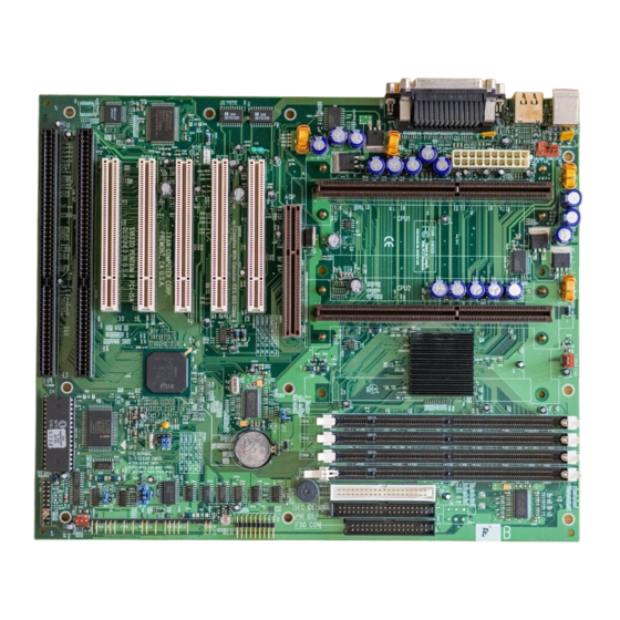
I. PRODUCT INFORMATION Flash/Upgrade BIOS protection Supports ACPI (Advanced Configuration and Power Interface) and OS Directed Power Management Supports SOFT power Virus warning supported Floppy drive swapping function supported System power LED LED Indicator ... - Page 11 I. PRODUCT INFORMATION Jumpers Clear CMOS (Real Time Clock) CPU Clock Ratio & CPU Type Expansion Sockets DIMM 1 to DIMM 4 Support DIMM Memory Expansion Slots...
- Page 12 I. PRODUCT INFORMATION CPU1 Slot 1 for supporting Pentium II CPU CPU2 Slot 1 for supporting Pentium II CPU ISA Slot 1 & Slot 2 16-bit ISA Bus Expansion Slot PCI Slot 1 to Slot 5 32-bit PCI Bus Expansion Slot Connectors PS/2 KB PS/2 Keyboard Connector (6-pin female)
- Page 13 I. PRODUCT INFORMATION Suspend Switch Connector (2 pins) SPEAKER Chassis Speaker Connector (4 pins) GRN LED Green Status LED Connector (3 pins) HDD LED HDD LED Connector (4 pins) RESET Reset Switch Connector (2 pins) PWR ON ATX Power Switch Connector (2 pins)
-
Page 14: Section 2: Hardware Installation
SECTION 2. HARDWARE INSTALLATION This section gives you a step-by-step procedure on how to install your system. Follow each section accordingly. Jumper Settings Please refer the following figures for the locations of the jumpers on the mainboard. 2-1.1 CMOS Clear Setting CMOS Default (Normal) - Page 15 II.HARDWARE INSTALLATION 2-1.2 CPU Type Setting CPU Type Default: 350MHz 1-2 & 7-8 This mainboard supports Dual Pentium II CPU. However, mixing two different CPU type is not allowed. That is, install the same CPU type if you have two CPU in your system.
-
Page 16: 2-2 Connectors
II.HARDWARE INSTALLATION 2-2 Connectors 2-2.1 Panel Connector PWR LED ATX Power LED Connector (3 pins) KBLCK Keyboard Lock Switch Connector (2 pins) Suspend Switch Connector (2 pins) SPEAKER Chassis Speaker Connector (4 pins) GRN LED Green Status LED Connector (3 pins) HDD LED HDD LED Connector (4 pins) RESET... -
Page 17: 2-2.2 Power Connector
II.HARDWARE INSTALLATION 2-2.2 Power Connector Connect the 20-pin ATX power supply cable to this power connector. Make sure the right plug-in direction and the power supply is off before connecting or disconnecting the power cable. 3.3V 3.3V Stand-by 2-2.3 Fan Connectors Connect the CPU and Chassis Fan cables to the fan connectors shown below. -
Page 18: 2-2.5 Keyboard Connector
II.HARDWARE INSTALLATION Connect the PS/2 mouse to the onboard 6-pin Mini-Din connector marked as MOUSE. PS/2 Mouse 2-2.5 Keyboard Connector Connect the PS/2 keyboard to the onboard 6-pin Mini-Din connector marked as KB. PS/2 Keyboard 2-2.6 USB Device Connector Connect your USB device(s) to the onboard USB connector marked as USB. -
Page 19: 2-2.7 Serial Device(Com1/Com2) Connector
II.HARDWARE INSTALLATION 2-2.7 Serial Device(COM1/COM2) Connectors Connect your serial device(s) to the onboard 9-pin serial connectors marked as COM1 and COM2. COM1 COM2 2-2.8 Printer Connctor Connect your local printer to the onboard 25-pin printer connector marked as PRINTER. PRINTER 2-2.9 Floppy Drive Connector... -
Page 20: 2-2.10 Ide Hard Disk And Cd-Rom Connector
II.HARDWARE INSTALLATION Connect the floppy drive cable to the onboard 34-pin floppy drive connector marked as FDD. 2-2.10 IDE Hard Disk and CD-ROM Connector Connect your IDE devices to the onboard 40-pin IDE connectors marked as Primary and Secondary. Secondary Primary... -
Page 21: 2-2.11 Irda Connector
II.HARDWARE INSTALLATION Secondary IDE Cable Master Slave Secondary Primary IDE Cable Master Slave Primary It is suggested that you connect the IDE devices to your IDE cables as the figure shown above. Each IDE channel, either Primary or Secondary, supports two IDE devices which must be set differently to master mode and slave mode. -
Page 22: 2-2.12 Sb-Link Connector
II.HARDWARE INSTALLATION 2-2.12 SB-LINK Connector If you have a Creative PCI sound card installed in your system, connect the sound card to this SB-LINK connector for compatibility issue under DOS environment. Description GNTA REQA SB-LINK SIRQ 2-2.13 Wake on LAN Connector This mainboard supports wake up on LAN function. -
Page 23: 2-2.14 Ring-On Connector
II.HARDWARE INSTALLATION 2-2.14 Ring-On Connector Connect the internal modem to this onboard RIN-ON connector to support the modem ring-on function. To use this function, you need a ring-on supported modem card. RIN-ON 2-3 System Memory Installation There are 4 pcs 168-pin DIMM (Dual Inline Memory Module) sockets on the mainboard which support Synchronous DRAM and Registered SDRAM, and allow you install system memory maximum up to IGB. -
Page 24: 2-3.1 Type
-8 = 7ns, and the maximum clock is 125MHz -7 = 8ns, and the maximum clock is 142MHz PC-100 = New Intel specification for high memory speed with 100MHz or above CPU Bus Clock. This motherboard supports all the above memory speed. For better system performance and reliability, we suggest that you use PC-100 SDRAM if 100MHz or above CPU Bus Clock is used in your system. -
Page 25: 2-3.4 2-Clock And 4-Clock
II.HARDWARE INSTALLATION The difference between buffered and non-buffered DIMM can be identified by the notch position shown above. 2-3.4 2-clock and 4-clock signal Both 2-clock and 4-clock SDRAM DIMM supported by this mainboard. 2-3.5 Parity and Non-parity This mainboard supports standard 64 bit (Non-parity) and 72 bit (Parity) DIMM modules. -
Page 26: 2-3.7 Suggested Sdram Combination
II.HARDWARE INSTALLATION 2-3.7 Suggested SDRAM combination This mainboard supports the following SDRAM combination. DIMM Bit size Single/Double No. of DIMM size Recommende Data Chip per side side chip 1M by 16 1Mx64 Single side 1M by 16 1Mx64 Double side 16MB 2M by 8 2Mx64... -
Page 27: Section 3: Cmos Setup Utility
SECTION 3. CMOS SETUP UTILITY BIOS Setup Main Menu This section tells you how to configure the system by changing BIOS setup options. To enter the BIOS Setup Utility, press DEL key during POST (Power- On Self Test). The BIOS Setup Main Menu will appear as shown below. The main menu displays a table of items which defines basic information about your system. -
Page 28: Standard Cmos Setup
III. CMOS SETUP UTILITY E S C To close the BIOS Setup Utility. To move around the screen. An item is highlighted if it is selected. To displays information about the highlighted item you selected. S H I F T + F 2 To Change the color scheme. - Page 29 III. CMOS SETUP UTILITY Date + / - or Page Up / Page To set the date, highlight the date area. Press Down to set the current date. The date format is month: Jan. ~ Dec., date: 1 ~ 31, and year: 1994 ~ 2079. ...
- Page 30 III. CMOS SETUP UTILITY Floppy Drive A Floppy Drive B Drive A / B: Select the floppy drive type installed in your system. - None The available options for Drive A and Drive B are: - 360KB - 5.25" 360KB 5.25”, 1.2MB 5.25”, 720KB 3.5”, 1.44MB 3.5”, - 1.2MB 5.25"...
-
Page 31: Bios Features Setup
III. CMOS SETUP UTILITY BIOS Features Setup This "BIOS Features Setup" option allows you to setup and improve your system features and performance. Virus Warning Virus Warning: When this item is enabled, it provides some protection against viruses which try to write to the boot sector and partition table - Enabled of your hard disk drive. - Page 32 III. CMOS SETUP UTILITY External Cache External Cache: This item controls Enable/Disable the external L2 cache. - Enabled Default: Enabled - Disabled CPU L2 Cache ECC Checking CPU L2 Cache ECC This item can be used to enable ECC (Error Checking and Checking: Correcting) function of the CPU level-2 cache memory.
- Page 33 III. CMOS SETUP UTILITY Swap Floppy Drive: If you have two floppy drives in your system, This item allows you to swap around the assigned drive letters so - Enabled that drive A becomes drive B, and drive B becomes drive - Disabled Default: Disabled ...
- Page 34 PCI VGA and some graphic accelerator devices such as MPEG/Video capture cards are installed in your - Enabled system. - Disabled Default: Disabled MPS V1.4 For Single CPU MPS V1.4 For MPS V1.4 is Intel’s Multiprocessor Specification. Set this...
-
Page 35: Chipset Features Setup
III. CMOS SETUP UTILITY Single CPU: item to disabled if your operating system does not support MPS V1.4. Currently, not much multiprocessor - Enabled operating system supporting the MPS V1.4. - Disabled Default: Disabled OS Select for DRAM > 64MB OS Select for This item is to patch that can not report correct memory DRAM >... - Page 36 III. CMOS SETUP UTILITY hardware. If you change the values, you may introduce fatal errors or recurring instability into your system. SDRAM CAS Latency SDRAM CAS This item defines the latency between SDRAM read Latency: command and the actual data time. - 2T It is an important SDRAM parameter.
- Page 37 III. CMOS SETUP UTILITY SDRAM RAS# Precharge Time SDRAM RAS# This item defines the waiting time after issuing a Precharge: SDRAM Precharge command. - 2T Default: 3T - 3T - Auto DRAM ECC Function DRAM ECC This item enables/disables ECC(Error Checking and Function: Correction) for the main memory.
- Page 38 III. CMOS SETUP UTILITY 8 Bit I/O Recovery 16 Bit I/O Recovery Time: Time: - NA This two items set timing parameters for 8-bit and 16- bit ISA expansion cards. Default: 8-Bit I/O Recovery Time => 4 - NA 8-Bit I/O Recovery Time => 1 ...
-
Page 39: Power Management Setup
III. CMOS SETUP UTILITY - 128 - 256 Pentium II Micro Codes Pentium II Micro This item defines the Pentium II Micro Codes which Codes: are used to resolve Pentium II CPU bugs. We recommend that you leave this item at the default - Enabled value for better reliability. - Page 40 III. CMOS SETUP UTILITY Power Management Power Management: This item allows you to set the default parameters of power-saving modes. Set to Disable to disable power - Max Saving management function. Set to User Define to define - Mix Saving your own parameters.
- Page 41 III. CMOS SETUP UTILITY - No Default: Yes Video Off After Video Off After: To select the power down mode option to turn off video monitor. - N/A - Doze Default: Standby - Standby - Suspend Doze Mode Doze Mode: This item lets you set the time after which the system enters into Doze mode from Working mode.
- Page 42 III. CMOS SETUP UTILITY - 8 Min detected by monitoring the IRQ signals or other I/O - 12 Min events. - 20 Min Default: Disabled - 30 Min - 40 Min - 1 Hour Suspend Mode Suspend Mode: This item lets you set the time after which the system enters into Suspend mode from Standby mode.
- Page 43 III. CMOS SETUP UTILITY Modem Wake Up Modem Wake Up: To enable or disable Modem Wake Up function. - Enabled Default: Disabled - Disabled LAN Wake Up LAN Wake Up: To enable or disable LAN Wake Up function. - Enabled Default: Disabled - Disabled...
- Page 44 III. CMOS SETUP UTILITY Power Button Override Power Button When set to Enabled, the power switch on the front Override: panel can be used to control power On/Suspend/Off. - Enabled - Disabled Press switch System status Less than 4 seconds Suspend mode Longer than 4 seconds Power off...
- Page 45 III. CMOS SETUP UTILITY IRQ 8 Clock Event IRQ 8 Clock Event: OS/2 has periodically IRQ8 RTC(Real Time Clock) event. When set this item to enabled, OS/2 may has - Enabled problem to go into Doze/Standby/Suspend mode. - Disabled Default: Disabled ...
-
Page 46: Pnp/Pci Configuration
III. CMOS SETUP UTILITY PNP/PCI Configuration Setup This option display a table of items that configures how PNP (Plug and Play) and PCI expansion cards operates in your system. PnP OS Installed PnP OS Installed: Normally, BIOS will allocate the PnP resources during POST (Power-On Self Test). - Page 47 III. CMOS SETUP UTILITY automatically for these PNP/PCI and onboard devices. The exception might be encountered when legacy ISA - Auto devices are installed, which occupies resources that - Manual BIOS can not know. Therefore, this option is for BIOS to know in advance that IRQ/DMA is occupied by legacy ISA devices if Manual is selected.
- Page 48 III. CMOS SETUP UTILITY DMA 0 DMA 1 DMA 3 DMA 5 DMA 6 DMA 7 DMA 0,1,3,5-7: Set the selected DMA channel to Legacy ISA if your ISA card is not PnP compatible card and requires a special DMA - Legacy ISA channel to make it function.
- Page 49 III. CMOS SETUP UTILITY Used MEM base This item lets you set a memory space for non-PnP addr: ISA card and specifies the memory base of the reserved memory space. - N/A - C800 Default: N/A - CC00 - D000 - D400 - D800 - DC00...
-
Page 50: Load Setup Defaults
III. CMOS SETUP UTILITY Load Setup Defaults This option allows you load BIOS optimized settings for optimum system performance. We recommend you to use the Optimal settings if your system has large memory size and fully loading with add-on cards. To load Setup Default, press Y key to confirm the operation when you see the above display. -
Page 51: Load Turbo Defaults
III. CMOS SETUP UTILITY Load Turbo Defaults This option provides better performance than optimal setup values. Load the turbo values if you have light system loading, that is, few add-on cards and memories. If your system has heavy loading (more add-on cards and memories), you may manually set the parameters in the "Chipset Features Setup"... -
Page 52: Integrated Peripherals
III. CMOS SETUP UTILITY Integrated Peripherals This option allows you to configure the I/O features. IDE HDD Block Mode IDE HDD Block This BIOS supports the enhanced IDE specification Mode: and allow multiple sectors access in a time when read/write. - Page 53 III. CMOS SETUP UTILITY IDE Primary Master PIO IDE Primary Slave PIO IDE Secondary Master PIO IDE Secondary Slave PIO Set these items to Auto to auto-detect the HDD speed. Primary/Secondary The PIO mode specifies the data transfer rate of HDD. Master/Secondary IDE HDD Mode Transfer Rate...
- Page 54 III. CMOS SETUP UTILITY Primary/Secondary Primary/Secondary IDE connector. PCI IDE: Default: Enabled - Enabled - Disabled USB Legacy Support USB Legacy Support: This BIOS simulates USB keyboard in legacy mode, which means during POST or under operating system, - Enabled you can use a USB keyboard without loading USB - Disabled driver.
- Page 55 III. CMOS SETUP UTILITY Default: Enabled Onboard Serial Port 1 Onboard Serial Port 2 Onboard Serial Port 1 This item allows you to select the I/O port and IRQ & 2: used by the onboard serial ports. - Auto Default: Onboard Serial Port 1=>...
-
Page 56: 3-10 Password Setting
III. CMOS SETUP UTILITY Parallel Port Mode Parallel Port Mode: This item allows you to set the parallel port mode. - SPP - EPP 1. SPP (Standard Parallel Port): IBM AT and PS/2 - ECP compatible mode - ECP + EPP 2. -
Page 57: 3-11 Ide Hdd Auto Detection
III. CMOS SETUP UTILITY dialog box appears. The system will ask you to confirm the new password by asking you to type it in a second time. Carefully type the password again and press ENTER, or just press ENTER if you are deleting a password that is already installed. -
Page 58: 3-12 Save & Exit Setup
III. CMOS SETUP UTILITY 3-12 Save & Exit Setup Highlight this item and press ENTER to save the changes that you have made in the setup utility and exit the setup program. When the Save and Exit dialog box appears, press Y to save and exit, or press N to return to the setup main menu. -
Page 59: Section 4: Bios/Software Utility
SECTION 4. BIOS/SOFTWARE UTILITY Flash Utility MAXFLASH.EXE This section tells you a step-by-step procedure on how to use the flash utility, “maxflash.exe”, upgrade your mainboard BIOS. To upgrade your motherboard BIOS, please follow the following: 1. For Win95 system, press F8 before Win95 boot-up, and select “Safe mode command prompt only”. -
Page 60: Bios Flash/Upgrade Protection
Remove Question Marks “?” in Win95 Device Manager Since some of Intel 440LX/EX latest technologies, like “ACPI”, “USB” & “Ultra DMA/33”, are so new, Win95 did not support them on Aug. of 1995 which is the moment Win'95 formal released. -
Page 61: Hardware Monitor (Optional)
IV.BIOS/SOFTWARE UTILITY 4-5 Hardware Monitor (Optional) If your mainboard supports hardware monitor function, the hardware monitor utility is available in the bundled CD title. You may run setup.exe directly to install the driver. After installation, you will see following screen if the program is active. Set the suggested low/high limit of system voltage, fan speed and temperature to monitor your system operating status. - Page 62 IV.BIOS/SOFTWARE UTILITY VcoreA CPU1 Voltage Suggested Low-High Limit: 1.81 to 3.01V VcoreB CPU2 Voltage Suggested Low-High Limit: 1.81 to 3.01V +3.3V +3.3V System Voltage Suggested Low-High Limit: 3.10 to 3.80V +5V System Voltage Suggested Low-High Limit: 4.50 to 5.50V +12V +12V System Voltage Suggested Low-High Limit: 11.0 to 13.0V –12V...
- Page 63 IV.BIOS/SOFTWARE UTILITY System System Temperature Suggested Low-High Limit: 0.0 to 60.0C CPU1 CPU1 Temperature Suggested Low-High Limit: 0.0 to 60.0C Other CPU2 Temperature Suggested Low-High Limit: 0.0 to 60.0C If any of the item is abnormal working or over the suggested low/high limit, there will be a “Warning Message”...
Need help?
Do you have a question about the BX and is the answer not in the manual?
Questions and answers