Table of Contents
Advertisement
Advertisement
Table of Contents

Related Manuals for Intel BLKDP35DPM


Summary of Contents for Intel BLKDP35DPM
- Page 1 Intel® Desktop Board DP35DP Product Guide Order Number: D87462-003...
-
Page 2: Revision History
WARRANTIES RELATING TO FITNESS FOR A PARTICULAR PURPOSE, MERCHANTABILITY, OR INFRINGEMENT OF ANY PATENT, COPYRIGHT OR OTHER INTELLECTUAL PROPERTY RIGHT. Intel products are not intended for use in medical, life saving, or life sustaining applications. Intel may make changes to specifications and product descriptions at any time, without notice. -
Page 3: Intended Audience
The suitability of this product for other PC or embedded non-PC applications or other environments, such as medical, industrial, alarm systems, test equipment, etc. may not be supported without further evaluation by Intel. Document Organization The chapters in this Product Guide are arranged as follows:... -
Page 4: Box Contents
Intel Desktop Board DP35DP Product Guide Conventions The following conventions are used in this manual: CAUTION Cautions warn the user about how to prevent damage to hardware or loss of data. NOTE Notes call attention to important information. Terminology The table below gives descriptions of some common terms used in the product guide. -
Page 5: Table Of Contents
Contents 1 Desktop Board Features Supported Operating Systems................10 Desktop Board Components.................11 Processor......................13 Main Memory.....................13 ® Intel P35 Express Chipset ..................14 Audio Subsystem ....................15 Legacy Input/Output (I/O) Controller ..............15 LAN Subsystem ....................16 RJ-45 LAN Connector LEDs................16 Hi-Speed USB 2.0 Support ..................17 Enhanced IDE Interface ..................17... - Page 6 4 Configuring for RAID (Intel Matrix Storage Technology) Configuring the BIOS for Intel Matrix Storage Technology ........65 Creating Your RAID Set ................65 Loading the Intel Matrix Storage Technology RAID Drivers and Software ....66 Setting Up a “RAID Ready” System ...............66...
- Page 7 Enabling Intel Rapid Recover Technology...............67 Creating a Recovery Volume ................68 Creating a Recovery Volume Using the RAID Option ROM .........68 Creating a Recovery Volume Using the Intel Matrix Storage Console ....68 Disk Synchronization Mode ..................69 Mounting the Recovery Disk ................69 A Error Messages and Indicators BIOS Beep Codes ....................71...
- Page 8 4. HD Audio Link Header Signal Names ...............47 5. IEEE 1394a Signal Header Names ..............47 6. Front Panel Intel High Definition Audio Header Signal Names ......47 7. Front Panel CIR Receiver (Input) Header Signal Names ........48 8. Back Panel CIR Header Emitter (Output) Header Signal Names ......48 9.
-
Page 9: Desktop Board Features
• Support for up to 8 GB of system memory ® Chipset Intel P35 Express Chipset consisting of: • Intel P35 Express Chipset Memory Controller Hub (MCH) ® • Intel 82801IR I/O Controller Hub (ICH9R) Graphics One PCI Express* x16 connector supporting PCI Express graphics... -
Page 10: Supported Operating Systems
Intel Desktop Board DP35DP Product Guide Table 1. Feature Summary (continued) ® BIOS • Intel Platform Innovation Framework for extensible firmware interface • 8 Mbit symmetrical flash memory device • Support for SMBIOS ® • Intel Rapid BIOS Boot ®... -
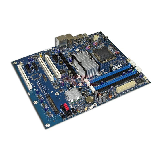
Page 11: Desktop Board Components
Desktop Board Features Desktop Board Components Figure 1 shows the approximate location of the major components on Desktop Board DP35DP. Figure 1. Desktop Board DP35DP Components... - Page 12 Intel Desktop Board DP35DP Product Guide Table 2. Desktop Board DP35DP Components Label Description PCI bus connector 3 Auxiliary chassis fan header (4-pin) PCI Express x1 connector 3 PCI Express x1 connector 2 High Definition Audio Link header PCI bus connector 2...
-
Page 13: Processor
Desktop Board may result in damage to the board, or the system may not function properly. Desktop Board DP35DP supports an Intel processor in the LGA775 package. Processors are not included with the Desktop Board and must be purchased separately. -
Page 14: Intel P35 Express Chipset
The MCH provides interfaces to the processor, memory, PCI Express bus, and the DMI interconnect. ICH9R is a centralized controller for the board’s I/O paths. Related Links: Go to the following link for more information about the Intel P35 Express Chipset: http://developer.intel.com/products/chipsets/index.htm... -
Page 15: Audio Subsystem
• A signal-to-noise (S/N) ratio of 95 dB • Independent multi-streaming 7.1 audio (using the back panel audio connectors) and stereo (using the Intel High Definition front panel audio header) • ADAT* optical interface support from the back panel S/PDIF optical port... -
Page 16: Lan Subsystem
Intel Desktop Board DP35DP Product Guide LAN Subsystem The LAN subsystem includes: • Intel ICH9R • Intel 82566DC Gigabit (10/100/1000 Mb/s) Ethernet LAN controller • RJ-45 LAN connector with integrated status LEDs The subsystem features: • CSMA/CD protocol engine • LAN connect interface between ICH9R and the LAN controller •... -
Page 17: Hi-Speed Usb 2.0 Support
Desktop Board Features Table 3 describes the LED states when the board is powered up and the LAN subsystem is operating. Table 3. LAN Connector LEDs LED Color LED State Indicates Green LAN link is not established LAN link is established Blinking LAN activity is occurring 10 Mb/s data rate... -
Page 18: Serial Ata
The recovery drive can be attached to your system via any standard SATA or eSATA connection. Intel Rapid Recover Technology also provides the added benefit of allowing the recovery drive to be mounted as a read-only volume so you can quickly copy files from the recovery drive when individual files need to be recovered. -
Page 19: Bios
Desktop Board Features BIOS The BIOS provides the Power-On Self-Test (POST), the BIOS Setup program, the PCI/PCI Express and IDE auto-configuration utilities, and the video BIOS. The BIOS is stored in the Serial Peripheral Interface (SPI) Flash. The BIOS can be updated by following the instructions on page 61 in Chapter 3. Serial ATA and IDE Auto Configuration If you install a Serial ATA or IDE device (such as a hard drive) in your computer, the auto-configuration utility in the BIOS automatically detects and configures the device... -
Page 20: Hardware Management Features
• Intel Quiet System Technology fan speed control, delivering acoustically-optimized thermal management NOTE Memory must be installed in the Channel A, DIMM 0 socket to enable Intel Quiet System Technology. • Fan speed controllers and sensors integrated into the ICH9R •... -
Page 21: Power Management Features
Desktop Board Features Power Management Features Power management is implemented at several levels, including: • Software support through the Advanced Configuration and Power Interface (ACPI) • Hardware support: ⎯ Power connectors ⎯ Fan headers ⎯ LAN wake capabilities ⎯ Instantly Available PC technology (Suspend to RAM) ⎯... -
Page 22: Fan Headers
Intel Desktop Board DP35DP Product Guide Fan Headers The function/operation of the fans is as follows: • The fans are on when the computer is in the ACPI S0 state. • The fans are off when the computer is in the ACPI S3, S4, or S5 state. -
Page 23: +5 V Standby Power Indicator Led
For more information on standby current requirements for the Desktop Board, refer to the Technical Product Specification by going to the following link, finding the product, and selecting Product Documentation from the left-hand menu: http://support.intel.com/support/motherboards/desktop/ Wake from USB NOTE Wake from USB requires the use of a USB peripheral that supports Wake from USB. -
Page 24: Pme# Signal Wake-Up Support
ENERGY STAR* Capable In 2007, the US Department of Energy and the US Environmental Protection Agency revised the ENERGY STAR requirements. Intel worked directly with these two governmental agencies to define the new requirements. Currently Intel Desktop Boards are capable of meeting the new ENERGY STAR requirements depending upon system configuration. -
Page 25: Installing And Replacing Desktop Board Components
2 Installing and Replacing Desktop Board Components This chapter tells you how to: • Install the I/O shield • Install and remove the Desktop Board • Install and remove a processor • Install and remove memory • Install and remove a PCI Express x16 card •... -
Page 26: Installation Precautions
Intel Desktop Board DP35DP Product Guide Installation Precautions When you install and test the Intel Desktop Board, observe all warnings and cautions in the installation instructions. To avoid injury, be careful of: • Sharp pins on connectors • Sharp pins on printed circuit assemblies •... -
Page 27: Installing The I/O Shield
Installing and Replacing Desktop Board Components Installing the I/O Shield The Desktop Board comes with an I/O shield. When installed in the chassis, the shield blocks radio frequency transmissions, protects internal components from dust and foreign objects, and promotes correct airflow within the chassis. Install the I/O shield before installing the Desktop Board in the chassis. -
Page 28: Installing And Removing The Desktop Board
Intel Desktop Board DP35DP Product Guide Installing and Removing the Desktop Board CAUTION Only qualified technical personnel should do this procedure. Disconnect the computer from its power source before performing the procedures described here. Failure to disconnect the power before you open the computer can result in personal injury or equipment damage. -
Page 29: Installing And Removing A Processor
Installing and Replacing Desktop Board Components Installing and Removing a Processor Instructions on how to install the processor to the Desktop Board are given below. Installing a Processor CAUTION Before installing or removing the processor, make sure the AC power has been removed by unplugging the power cord from the computer;... -
Page 30: Lift The Load Plate
Intel Desktop Board DP35DP Product Guide 3. Lift the load plate (Figure 7, A). Do not touch the socket contacts (Figure 7, B). Figure 7. Lift the Load Plate 4. Remove the plastic protective socket cover from the load plate (Figure 8). Do not discard the protective socket cover. -
Page 31: Remove The Processor From The Protective Processor Cover
Installing and Replacing Desktop Board Components 5. Remove the processor from the protective processor cover. Hold the processor only at the edges, being careful not to touch the bottom of the processor (see Figure 9). Do not discard the protective processor cover. Always replace the processor cover if the processor is removed from the socket. -
Page 32: Installing The Processor Fan Heat Sink
Intel Desktop Board DP35DP Product Guide 7. Pressing down on the load plate (Figure 11, A), close and engage the socket lever (Figure 11, B). Figure 11. Close the Load Plate Installing the Processor Fan Heat Sink Desktop Board DP35DP has mounting holes for a processor fan heat sink. For instructions on how to attach the processor fan heat sink to the Desktop Board, refer to the boxed processor manual. -
Page 33: Connecting The Processor Fan Heat Sink Cable
Installing and Replacing Desktop Board Components Connecting the Processor Fan Heat Sink Cable Connect the processor fan heat sink cable to the 4-pin processor fan header (see Figure 12). A fan with a 4-pin connector as shown in Figure 12, A is recommended; however, a fan with a 3-pin connector (Figure 12, B) can be used. -
Page 34: Removing The Processor
Installing and Removing Memory NOTE To be fully compliant with all applicable Intel SDRAM memory specifications, the board requires DIMMs that support the Serial Presence Detect (SPD) data structure. Desktop board DP35DP has four 240-pin DDR2 DIMM sockets arranged as DIMM 0 and DIMM 1 in both Channel A and Channel B. -
Page 35: Guidelines For Dual Channel Memory Configuration
Installing and Replacing Desktop Board Components Guidelines for Dual Channel Memory Configuration Before installing DIMMs, read and follow these guidelines for dual channel configuration. Two or Four DIMMs Install a matched pair of DIMMs equal in speed and size (see Figure 13) in DIMM 0 (blue) of channels A and B. -
Page 36: Three Dimms
Intel Desktop Board DP35DP Product Guide Three DIMMs If you want to use three DIMMs in a dual-channel configuration, install a matched pair of DIMMs equal in speed and size in DIMM 0 (blue) and DIMM 1 (black) of channel A. -
Page 37: Installing Dimms
Installing and Replacing Desktop Board Components Installing DIMMs To make sure you have the correct DIMM, place it on the illustration of the DDR2 DIMM in Figure 16. All the notches should match with the DDR2 DIMM. Figure 16. Use DDR2 DIMMs... -
Page 38: Installing A Dimm
Intel Desktop Board DP35DP Product Guide NOTE Memory must be installed in the Channel A, DIMM 0 socket to enable Intel Quiet System Technology. To install a DIMM, follow these steps: 1. Observe the precautions in "Before You Begin" on page 25. -
Page 39: Removing Dimms
Installing and Replacing Desktop Board Components 7. Insert the bottom edge of the DIMM into the socket. 8. When the DIMM is inserted, push down on the top edge of the DIMM until the retaining clips snap into place. Make sure the clips are firmly in place. 9. -
Page 40: Installing And Removing A Pci Express X16 Card
Intel Desktop Board DP35DP Product Guide Installing and Removing a PCI Express x16 Card CAUTION When installing a PCI Express x16 card on the Desktop Board, ensure that the card is fully seated in the PCI Express x16 connector before you power on the system. If the card is not fully seated in the PCI Express connector, an electrical short may result across the PCI Express connector pins. -
Page 41: Removing The Pci Express X16 Card
Installing and Replacing Desktop Board Components Removing the PCI Express x16 Card Follow these instructions to remove the PCI Express x16 card from the connector: 1. Observe the precautions in "Before You Begin" on page 25. 2. Remove the screw (Figure 19, A) that secures the card’s metal bracket to the chassis back panel. -
Page 42: Connecting The Ide Cable
For correct function of the cable: • Observe the precautions in "Before You Begin" on page 25. • Attach the cable end with the single connector (blue) to the Intel Desktop Board (Figure 20, A). • Attach the cable end with the two closely spaced connectors (gray and black) to the... -
Page 43: Connecting The Ide Cable
Installing and Replacing Desktop Board Components Figure 20. Connecting the IDE Cable... -
Page 44: Connecting The Serial Ata (Sata) Cables
Intel Desktop Board DP35DP Product Guide Connecting the Serial ATA (SATA) Cables SATA cables support the Serial ATA protocol. Each cable can be used to connect a single internal SATA drive to the Desktop Board. For correct cable function: 1. Observe the precaution in “Before You Begin” on page 25. -
Page 45: Installing The External Serial Ata Adapter Bracket
Installing and Replacing Desktop Board Components Installing the External Serial ATA Adapter Bracket If you are connecting the external Serial ATA (eSATA) adapter bracket to the Desktop Board, follow these instructions (see Figure 22): 1. Observe the precautions in “Before You Begin” on page 25. 2. -
Page 46: Connecting To The Internal Headers
Intel Desktop Board DP35DP Product Guide Connecting to the Internal Headers Before connecting cables to the internal headers, observe the precautions in “Before You Begin” on page 25. Figure 23 shows the location of the internal headers. Item Description Item... -
Page 47: Connecting To The Hd Audio Link Header
Definition Audio Figure 23, C shows the location of the front panel audio header. Table 6 shows the pin assignments for the front panel audio header. Table 6. Front Panel Intel High Definition Audio Header Signal Names Signal Name Signal Name... -
Page 48: Connecting To The Consumer Ir (Cir) Headers
Intel Desktop Board DP35DP Product Guide To install the cable that connects the front panel audio solution to the front panel audio header, follow these steps: 1. Observe the precautions in "Before You Begin" on page 25. 2. Turn off all peripheral devices connected to the computer. Turn off the computer and disconnect the AC power cord. -
Page 49: Connecting To The Serial Port Header
Installing and Replacing Desktop Board Components Connecting to the Serial Port Header See Figure 23, E for the location of the serial port header. Table 9 shows the pin assignments for the header. Table 9. Serial Port Header Signal Names Signal Name Signal Name RXD#... -
Page 50: Connecting To The Front Panel Header
Intel Desktop Board DP35DP Product Guide Connecting to the Front Panel Header Before connecting to the front panel header, observe the precautions in "Before You Begin" on page 25. See Figure 23, I on page 46 for the location of the multi-colored front panel header. -
Page 51: Connecting To The Flexible Audio System
Installing and Replacing Desktop Board Components Connecting to the Flexible Audio System After installing the SigmaTel* audio driver from the Intel Express Installer DVD-ROM, the multi-channel audio feature can be enabled. Figure 24 shows the back panel audio connectors. The default connector assignments are shown in the table. -
Page 52: Connecting Chassis Fan And Power Supply Cables
Intel Desktop Board DP35DP Product Guide Connecting Chassis Fan and Power Supply Cables Connecting Chassis Fan Cables Connect chassis fan cables to the 3-pin and 4-pin chassis fan headers on the Desktop Board. Figure 25 shows the location of the chassis fan headers. -
Page 53: Connecting Supply Power Cables
Installing and Replacing Desktop Board Components Connecting Supply Power Cables CAUTION Failure to use an appropriate power supply and/or not connecting the 12 V (2 x 2 pin) power connector to the Desktop Board may result in damage to the board or the system may not function properly. -
Page 54: Setting The Bios Configuration Jumper
Intel Desktop Board DP35DP Product Guide Setting the BIOS Configuration Jumper NOTE Always turn off the power and unplug the power cord from the computer before moving the jumper. Moving the jumper with the power on may result in unreliable computer operation. -
Page 55: Clearing Passwords
Installing and Replacing Desktop Board Components Table 14. Jumper Settings for the BIOS Setup Program Modes Jumper Setting Mode Description Normal (default) (1-2) The BIOS uses the current configuration and passwords for booting. Configure (2-3) After the Power-On Self-Test (POST) runs, the BIOS displays the Maintenance Menu. -
Page 56: Replacing The Battery
Intel Desktop Board DP35DP Product Guide 11. Remove the computer cover. 12. To restore normal operation, place the jumper on pins 1-2 as shown below. 13. Replace the cover, plug in the computer, and turn on the computer. Replacing the Battery A coin-cell battery (CR2032) powers the real-time clock and CMOS memory. - Page 57 Installing and Replacing Desktop Board Components VIKTIGT! Risk för explosion om batteriet ersätts med felaktig batterityp. Batterier ska kasseras enligt de lokala miljövårdsbestämmelserna. VARO Räjähdysvaara, jos pariston tyyppi on väärä. Paristot on kierrätettävä, jos se on mahdollista. Käytetyt paristot on hävitettävä paikallisten ympäristömääräysten mukaisesti.
- Page 58 Intel Desktop Board DP35DP Product Guide UPOZORNÌNÍ V případě výměny baterie za nesprávný druh může dojít k výbuchu. Je-li to možné, baterie by měly být recyklovány. Baterie je třeba zlikvidovat v souladu s místními předpisy o životním prostředí. Προσοχή Υπάρχει κίνδυνος για έκρηξη σε περίπτωση που η μπαταρία αντικατασταθεί από μία...
- Page 59 Installing and Replacing Desktop Board Components UPOZORNENIE Ak batériu vymeníte za nesprávny typ, hrozí nebezpečenstvo jej výbuchu. Batérie by sa mali podľa možnosti vždy recyklovať. Likvidácia použitých batérií sa musí vykonávať v súlade s miestnymi predpismi na ochranu životného prostredia. POZOR Zamenjava baterije z baterijo drugačnega tipa lahko povzroči eksplozijo.
- Page 60 Intel Desktop Board DP35DP Product Guide To replace the battery, follow these steps: 1. Observe the precautions in "Before You Begin" (see page 25). 2. Turn off all peripheral devices connected to the computer. Disconnect the computer’s power cord from the AC power source (wall outlet or power adapter).
-
Page 61: Updating The Bios
Power-On Self-Test (POST) memory test begins and before the operating system boot begins. This chapter tells you how to update the BIOS by either using the Intel Express BIOS Update utility or the Iflash Memory Update utility, and how to recover the BIOS if an update fails. -
Page 62: Updating The Bios With The Iso Image Bios Update File Or The Iflash Memory Update Utility
• Intel Flash Memory Update Utility You can obtain either of these files through your computer supplier or by navigating to the Desktop Board DP35DP page on the Intel World Wide Web site at: http://support.intel.com/support/motherboards/desktop Navigate to the DP35DP page, click “[view] Latest BIOS updates,” and select the ISO Image BIOS Update or Iflash BIOS Update utility file. -
Page 63: Updating The Bios With The Iflash Memory Update Utility
CD-ROM, bootable USB flash drive, or other bootable USB media. The utility available on the Intel World Wide Web site provides a simple method for creating a bootable CD-ROM that will automatically update your BIOS. The Iflash BIOS update files can also be extracted locally to your hard drive and copied to a bootable USB flash drive or other bootable USB media. -
Page 64: Recovering The Bios
BIOS could be damaged. Due to BIOS size and recovery requirements, a CD-R with the .BIO file in the root directory will be required. Related Links: For more information about updating the Intel Desktop Board BIOS or recovering from a BIOS update failure, go to: http://support.intel.com/support/motherboards/desktop/sb/CS-022312.htm... -
Page 65: Configuring For Raid (Intel Matrix Storage Technology)
4. Then save your settings by pressing <F10>. Creating Your RAID Set 1. Upon re-boot, you will see the following Intel Matrix Storage Manager option ROM status message on the screen: Press <Ctrl-I> to enter the RAID Configuration Utility. Press <Ctrl-I> and enter the RAID Configuration Utility. -
Page 66: Loading The Intel Matrix Storage Technology Raid Drivers And Software
3. Finish the Windows installation and install all necessary drivers. 4. Install the Intel Matrix Storage Console software via the Intel Express Installer CD included with your desktop board or after downloading it from the Internet at http://support.intel.com/support/motherboards/desktop/. The Intel Matrix Storage Console software can be used to manage the RAID configuration. -
Page 67: Configuring For Intel Rapid Recover Technology
NOTE Intel Rapid Recover Technology does not support RAID 5. Intel Rapid Recover Technology can be Enabled or Disabled in the system BIOS menu. To enable Intel Rapid Recover Technology, complete following steps: 1. Enter the BIOS menu by pressing the <F2> key early during system POST. -
Page 68: Creating A Recovery Volume
Creating a Recovery Volume Using the Intel Matrix Storage Console To create a recovery volume using the Intel Matrix Storage Console, the system must be configured in RAID mode with two drives. Boot the system into Microsoft Windows and open the Intel Matrix Storage Console application. -
Page 69: Disk Synchronization Mode
There are two modes of updating or synchronizing the recovery disk with the master disk – either continuous update or manual update. To change from Continuous Update mode to Update On Request mode using the Intel Matrix Storage Console, select the Advanced mode from the View menu, right-click on the recovery volume, and select Disable Continuous Update. - Page 70 To un-mount the recovery disk, complete the following steps: 1. In the Advanced mode, right-click on the recovery volume name. 2. Select Access Recovery Drive Files. 3. Select OK on the information dialog box. The recovery disk is now un-mounted and reappears in Intel Matrix Storage Console.
-
Page 71: A Error Messages And Indicators
A Error Messages and Indicators Desktop Board DP35DP reports POST errors in two ways: • By sounding a beep code • By displaying an error message on the monitor BIOS Beep Codes The BIOS also issues a beep code (one long tone followed by two short tones) during POST if the video configuration fails (a faulty video card or no card installed) or if an external ROM module does not properly checksum to zero. - Page 72 Intel Desktop Board DP35DP Product Guide...
-
Page 73: B Regulatory Compliance
B Regulatory Compliance This appendix contains the following regulatory compliance information for Desktop Board DP35DP: • Safety regulations • European Union Declaration of Conformity statement • Product Ecology statements • Electromagnetic Compatibility (EMC) regulations • Product certifications Safety Regulations Desktop Board DP35DP complies with the safety regulations stated in Table 17 when correctly installed in a compatible host system. -
Page 74: European Union Declaration Of Conformity Statement
Intel Desktop Board DP35DP Product Guide European Union Declaration of Conformity Statement We, Intel Corporation, declare under our sole responsibility that the product Intel ® Desktop Board DP35DP is in conformity with all applicable essential requirements necessary for CE marking, following the provisions of the European Council Directive 89/336/EEC (EMC Directive) and Council Directive 73/23/EEC (Safety/Low Voltage Directive). - Page 75 Regulatory Compliance Lietuvių Šis produktas atitinka Europos direktyvų 89/336/EEC ir 73/23/EEC nuostatas. Malti Dan il-prodott hu konformi mal-provvedimenti tad-Direttivi Ewropej 89/336/EEC u 73/23/EEC. Norsk Dette produktet er i henhold til bestemmelsene i det europeiske direktivet 89/336/ EEC & 73/23/EEC. Polski Niniejszy produkt jest zgodny z postanowieniami Dyrektyw Unii Europejskiej 89/336/EWG i 73/23/EWG.
-
Page 76: Product Ecology Statements
当的重复使用处理。 请参考http://www.intel.com/intel/other/ehs/product_ecology 了解此计划的详情,包括涉及产品之范围、回收地点、运送指导、条款和条件等。 Deutsch Als Teil von Intels Engagement für den Umweltschutz hat das Unternehmen das Intel Produkt-Recyclingprogramm implementiert, das Einzelhandelskunden von Intel Markenprodukten ermöglicht, gebrauchte Produkte an ausgewählte Standorte für ordnungsgemäßes Recycling zurückzugeben. Details zu diesem Programm, einschließlich der darin eingeschlossenen Produkte, verfügbaren Standorte, Versandanweisungen, Bedingungen usw., finden Sie auf der... - Page 77 Regulatory Compliance Français Dans le cadre de son engagement pour la protection de l'environnement, Intel a mis en œuvre le programme Intel Product Recycling Program (Programme de recyclage des produits Intel) pour permettre aux consommateurs de produits Intel de recycler les produits usés en les retournant à...
-
Page 78: Lead-Free Desktop Board
Intel Desktop Board DP35DP Product Guide Türkçe Intel, çevre sorumluluğuna bağımlılığının bir parçası olarak, perakende tüketicilerin Intel markalı kullanılmış ürünlerini belirlenmiş merkezlere iade edip uygun şekilde geri dönüştürmesini amaçlayan Intel Ürünleri Geri Dönüşüm Programı’nı uygulamaya koymuştur. Bu programın ürün kapsamı, ürün iade merkezleri, nakliye talimatları, kayıtlar ve şartlar v.s dahil bütün ayrıntılarını... - Page 79 0.1% by weight (1000 ppm). China RoHS/Environmentally Friendly Use Period Logo: This an example of the symbol used on Intel Desktop Boards and associated collateral. The color of the mark may vary depending upon the application. The Environmental Friendly Usage...
-
Page 80: Emc Regulations
Intel Desktop Board DP35DP Product Guide EMC Regulations Desktop Board DP35DP complies with the EMC regulations stated in Table 19 when correctly installed in a compatible host system. Table 19. EMC Regulations Regulation Title FCC Class B Title 47 of the Code of Federal Regulations, Parts 2 and 15, Subpart B, Radio Frequency Devices. -
Page 81: Ensure Electromagnetic Compatibility (Emc) Compliance
Regulatory Compliance Japanese Kanji statement translation: This is a Class B product based on the standard of the Voluntary Control Council for Interference from Information Technology Equipment (VCCI). If this is used near a radio or television receiver in a domestic environment, it may cause radio interference. -
Page 82: Product Certifications
Description Mark UL joint US/Canada Recognized Component mark. Includes adjacent UL file number for Intel Desktop Boards: E210882. FCC Declaration of Conformity logo mark for Class B equipment. Includes Intel name and DP35DP model designation. CE mark. Declaring compliance to European Union (EU) EMC directive (89/336/EEC) and Low Voltage directive (73/23/EEC). -
Page 83: Chassis And Component Certifications
Regulatory Compliance Chassis and Component Certifications Ensure that the chassis and certain components; such as the power supply, peripheral drives, wiring, and cables; are components certified for the country or market where used. Agency certification marks on the product are proof of certification. Typical product certifications include: In Europe The CE marking signifies compliance with all applicable European requirements. - Page 84 Intel Desktop Board DP35DP Product Guide...
Need help?
Do you have a question about the BLKDP35DPM and is the answer not in the manual?
Questions and answers