Table of Contents
Advertisement
Quick Links
Advertisement
Table of Contents

Subscribe to Our Youtube Channel
Related Manuals for Intel BI440ZX


Summary of Contents for Intel BI440ZX
- Page 1 BI440ZX Motherboard Product Guide Order Number: 726091-002...
-
Page 2: Revision History
Disclaimer Intel Corporation (Intel) makes no warranty of any kind with regard to this material, including, but not limited to, the implied warranties of merchantability and fitness for a particular purpose. Intel assumes no responsibility for any errors that may appear in this document. -
Page 3: Table Of Contents
Contents 1 Motherboard Features Feature Summary......................... 7 Components......................... 8 Microprocessor........................9 Main Memory ........................9 PCI Enhanced IDE Interface ....................10 Input/Output (I/O) Controller ....................10 Real-Time Clock......................... 11 USB Support ........................11 Accelerated Graphics Port (AGP)..................12 BIOS ..........................12 Expansion Slots........................ - Page 4 BI440ZX Motherboard Product Guide 4 BIOS Setup Program Maintenance Menu......................33 Main Menu ......................... 34 Advanced Menu ......................... 35 Boot Setting Configuration Submenu................. 35 Peripheral Configuration Submenu ................36 IDE Configuration ...................... 38 IDE Configuration Submenus ..................39 Diskette Configurations Submenu................40 Event Log Configuration ....................
- Page 5 Contents Connecting the Processor Fan Cable to the Processor Fan Connector ..... 19 Installing a DIMM....................... 21 Removing the Battery ....................23 Connector Groups ..................... 45 Back Panel Connectors ..................... 46 Midboard Connectors ....................47 Front Panel Connector....................48 Location of the Jumper Blocks................... 49 Tables Processors Supported by the Motherboard ..............
- Page 6 BI440ZX Motherboard Product Guide...
-
Page 7: Motherboard Features
1 Motherboard Features This chapter gives an overview of the BI440ZX motherboard. The remaining chapters discuss: • How to add or upgrade components like processors or memory • How to invoke the BIOS Setup program to modify the motherboard’s configuration •... -
Page 8: Components
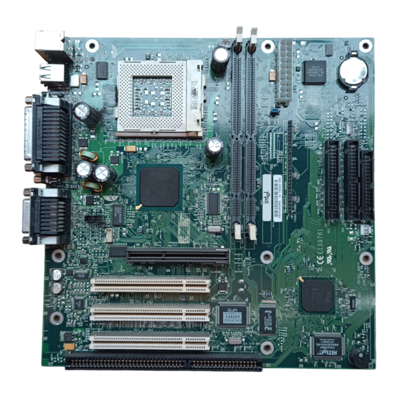
Digital Controller (optional) Battery AGP connector Diskette drive connector Intel 82443ZX PAC IDE connectors PCI bus add-in card connectors Intel 82371EB PIIX4E ISA bus add-in card connector Figure 1. Motherboard Components NOTE Components labeled optional do not come on all BI440ZX motherboards. -
Page 9: Microprocessor
For information about Refer to Installing a processor Page 17 Processor support for the BI440ZX motherboard http://support.intel.com/support/motherboards/desktop Main Memory The motherboard has two sockets for installing DIMMs. Minimum memory size is 16 MB; maximum memory size is 256 MB. The motherboard supports the following memory features: •... -
Page 10: Pci Enhanced Ide Interface
Refer to The location of the IDE connectors Figure 13, page 47 The PIIX4E PCI IDE controller BI440ZX Motherboard Technical Product Specification available through: http://support.intel.com/support/motherboards/desktop Input/Output (I/O) Controller The I/O controller handles the exchange of information between the processor and external devices like the mouse and keyboard or a printer that are connected to the computer. -
Page 11: Real-Time Clock
The recommended method of accessing the date in systems with Intel motherboards is indirectly from the Real-Time Clock (RTC) via the BIOS. The BIOS on Intel motherboards and baseboards contains a century checking and maintenance feature that checks the least two significant digits of the year stored in the RTC during each BIOS request (INT 1Ah) to read the date and, if less than 80 (i.e., 1980 is the first year supported by the PC), updates the century byte to 20. -
Page 12: Accelerated Graphics Port (Agp)
Refer to The location of the AGP connector Figure 1, page 8 Features of the AGP interface BI440ZX Motherboard Technical Product Specification available through: http://support.intel.com/support/motherboards/desktop BIOS The motherboard’s system BIOS is contained in a flash memory device on the motherboard. The BIOS provides the power-on self test (POST), the BIOS Setup program, and the PCI and IDE auto- configuration utilities. -
Page 13: Power Management
(APM) and Advanced Configuration and Power Interface (ACPI). If the board is used with an ACPI-aware operating system, the BIOS provides ACPI support. Otherwise, it defaults to APM support. For information about Refer to BI440ZX Motherboard Technical Product Specification How the board supports APM and ACPI available through: http://support.intel.com/support/motherboards/desktop Battery A battery on the motherboard keeps the clock and the values in CMOS RAM current when your computer is turned off. -
Page 14: Wake On Lan Technology
The location of the Wake on LAN technology Figure 13, page 47 connector Wake on LAN technology BI440ZX Motherboard Technical Product Specification available through: http://support.intel.com/support/motherboards/desktop CAUTION For Wake on LAN, the 5-V standby line for the power supply must be capable of delivering +5 V ±... -
Page 15: Installing And Replacing Motherboard Components
2 Installing and Replacing Motherboard Components This chapter tells you how to: • Install and remove the motherboard • Install and remove the processor • Install and remove memory • Replace the battery Before You Begin CAUTION Before you install this motherboard in a chassis, see Appendix B for regulatory requirements and precautions. -
Page 16: How To Install And Remove The Motherboard
BI440ZX Motherboard Product Guide How to Install and Remove the Motherboard Refer to your chassis manual for instructions on installing and removing the motherboard. The motherboard is secured to the chassis by eight screws. Figure 2 shows the locations of the mounting screw holes. -
Page 17: How To Install A Celeron Processor
Installing and Replacing Motherboard Components ™ How to Install a Celeron Processor To install a processor, follow these instructions: 1. Observe the precautions in “Before You Begin” (see page 15). 2. Raise the socket handle completely (see Figure 3). Figure 3. Raising the Socket Handle 3. -
Page 18: Closing The Handle
BI440ZX Motherboard Product Guide 4. Close the handle completely (see Figure 5). Figure 5. Closing the Handle 5. Peel back the plastic cover from the thermal interface on the bottom of the fan heatsink. Place the fan heatsink on top of the processor (see Figure 6). -
Page 19: Attaching The Fan Heatsink Clip
Installing and Replacing Motherboard Components 6. Attach the fan heatsink clip to the processor socket (see Figure 7). Fan Heatsink Clip Processor Socket Figure 7. Attaching the Fan Heatsink Clip 7. Connect the processor fan cable to the processor fan connector (see Figure 8). OM07491 Processor Fan Cable Processor Fan Connector... -
Page 20: How To Remove A Celeron Processor
The BIOS detects the size and type of installed memory. NOTE All memory components and DIMMs used with the BI440ZX motherboard must comply with the PC SDRAM Specifications. These include: the PC SDRAM Specification (memory component specific), the PC unbuffered SDRAM Specifications, and the PC Serial Presence Detect Specification. -
Page 21: How To Remove Memory
Installing and Replacing Motherboard Components 7. Insert the bottom edge of the DIMM into the socket (as shown in Figure 9). 8. When the DIMM is seated, push down on the top edge of the DIMM until the retaining clips snap into place. -
Page 22: How To Replace The Battery
BI440ZX Motherboard Product Guide How to Replace the Battery When your computer is turned off, a lithium battery maintains the current time-of-day clock and the values in CMOS RAM current. Figure 10 on page 23 shows the location of the battery. -
Page 23: Removing The Battery
Installing and Replacing Motherboard Components To replace the battery, follow these steps: 1. Observe the precautions in “Before You Begin” (see page 15). 2. Turn off all peripheral devices connected to the computer. Turn off the computer. 3. Remove the computer cover. 4. - Page 24 BI440ZX Motherboard Product Guide...
-
Page 25: Using The Bios Setup Program
• Clear passwords For information about Refer to The contents of the BIOS Setup Program screens Chapter 4, beginning on page 33 BI440ZX Motherboard Technical Product Specification The BIOS Setup program’s menus, options, and defaults settings available through: http://support.intel.com/support/motherboards/desktop NOTE For reference purposes, you should write down the current Setup settings. -
Page 26: Function Keys
BI440ZX Motherboard Product Guide NOTE The Setup menus described in this section apply to BI440ZX motherboards with BIOS identifier 4B4IZOXA.86A. Motherboards with other BIOS identifiers might have differences in some of the Setup menu screens. Table 4 is an overview of the menu screens in the BIOS Setup program. -
Page 27: How To Upgrade The Bios
• ® Intel Flash Memory Update Utility You can obtain the BIOS upgrade file through your computer supplier or from the Intel World Wide Web site: http://support.intel.com/support/motherboards/desktop/ NOTE Please review the instructions distributed with the update utility before attempting a BIOS upgrade. -
Page 28: Creating A Bootable Diskette
BIOS.EXE file and type: BIOS.EXE BIOS A: 8. Press <Enter> 9. The diskette now holds the new BIOS files, the Intel Flash Update Utility, and the recovery files. -
Page 29: Performing The Bios Upgrade
Using the BIOS Setup Program Performing the BIOS Upgrade 1. Boot the computer with the BIOS upgrade diskette in drive A. Press to go to the <Enter> Main Menu. The flash memory update utility screen appears. 2. Select . Press Update flash memory area from a file <Enter>... -
Page 30: How To Change The Bios Language
You can use the BIOS upgrade utility to change the language the BIOS uses for messages and the BIOS Setup program. Use a bootable diskette containing the Intel Flash Memory Update Utility and language files (see “Performing the BIOS Upgrade” on page 29). -
Page 31: How To Clear The Passwords
Using the BIOS Setup Program How to Clear the Passwords This procedure assumes that the motherboard is installed in the computer and the configuration jumper block is set to normal mode. 1. Observe the precautions in “Before You Begin” (see page 15). 2. - Page 32 BI440ZX Motherboard Product Guide...
-
Page 33: Bios Setup Program
This chapter describes the contents of the BIOS Setup Program’s screens. NOTE The Setup screens described in this section apply to BI440ZX motherboards with BIOS identifier 4B4IZOXA.86A. Motherboards with other BIOS identifiers might have differences in some of the Setup screens. -
Page 34: Main Menu
Italian • Spanish Cache Bus ECC [N/A] Cache bus ECC is not supported. Memory [Non-ECC] Not supported. (The Intel 82443ZX PAC does not provide Configuration ECC support.) System Time Hour, minute, and Specifies the current time. second System Date Month, day, and year... -
Page 35: Advanced Menu
BIOS Setup Program Advanced Menu This menu is for setting advanced features that are available through the chipset. Table 9. Advanced Menu Feature Options Description Boot Setting Configuration No options Configures Plug and Play and the Numlock key, and resets configuration data. -
Page 36: Peripheral Configuration Submenu
BI440ZX Motherboard Product Guide Peripheral Configuration Submenu This submenu is used for configuring the computer peripherals. Table 11. Peripheral Configuration Submenu Feature Options Description • Serial port A Disabled Configures serial port A. • Enabled Auto assigns the first free COM port, normally COM1, the address 3F8h, and the interrupt IRQ4. - Page 37 BIOS Setup Program Table 11. Peripheral Configuration Submenu (continued) Feature Options Description • Parallel port Disabled Configures the parallel port. • Auto assigns LPT1 the address 378h and the interrupt Enabled IRQ7. • Auto (default) An * (asterisk) displayed next to an address indicates a conflict with another device.
-
Page 38: Ide Configuration
BI440ZX Motherboard Product Guide IDE Configuration Table 12. IDE Device Configuration Feature Options Description • IDE Controller Disabled Specifies the integrated IDE controller. • Primary enables only the Primary IDE Controller. Primary Secondary enables only the Secondary IDE Controller. •... -
Page 39: Ide Configuration Submenus
BIOS Setup Program IDE Configuration Submenus This submenu is for configuring IDE devices, including: • Primary IDE master • Primary IDE slave • Secondary IDE master • Secondary IDE slave Table 13. IDE Configuration Submenus Feature Options Description • Type None Specifies the IDE configuration mode for IDE devices. -
Page 40: Diskette Configurations Submenu
BI440ZX Motherboard Product Guide Diskette Configurations Submenu This submenu is for configuring the diskette drive. Table 14. Diskette Configurations Submenu Feature Options Description • Diskette Controller Disabled Disables or enables the integrated diskette controller. • Enabled (default) • Diskette A:... -
Page 41: Video Configuration Submenu
BIOS Setup Program Video Configuration Submenu This submenu is for configuring video features. Table 16. Video Configuration Submenu Feature Options Description • Palette Snooping Disabled (default) Controls the ability of a primary PCI graphics controller to share a common palette with an •... -
Page 42: Power Menu
BI440ZX Motherboard Product Guide Power Menu This menu is for setting power management features. Table 19. Power Menu Feature Options Description Power Management • Disabled Enables or disables the BIOS power management feature. • Enabled (default) • Inactivity Timer Specifies the amount of time before the computer enters standby mode. -
Page 43: Boot Menu
BIOS Setup Program Boot Menu This menu is for setting the boot features and the boot sequence. Table 20. Boot Menu Feature Options Description • Quiet Boot Disabled Disabled displays normal POST messages. • Enabled displays OEM logo instead of POST messages. Enabled (default) •... -
Page 44: Exit Menu
BI440ZX Motherboard Product Guide Exit Menu This menu is for exiting the BIOS Setup program, saving changes, and loading and saving defaults. Table 21. Exit Menu Feature Description Exit Saving Changes Exits and saves the changes in CMOS SRAM. Exit Discarding Changes Exits without saving any changes made in the BIOS Setup program. -
Page 45: Technical Reference
The motherboard’s connectors can be divided into three groups, as shown in Figure 11. For information about Refer to Pin descriptions of the motherboard connectors BI440ZX Motherboard Technical Product Specification available through: http://support.intel.com/support/motherboards/desktop Back panel connectors (see page 46) Midboard connectors (see page 47) -
Page 46: Back Panel Connectors
BI440ZX Motherboard Product Guide Back Panel Connectors Figure 12 shows the back panel connectors on the motherboard. OM07465 † PS/2 keyboard or mouse G Serial port B PS/2 keyboard or mouse MIDI/Game port USB port 0 Audio line out USB port 1... -
Page 47: Midboard Connectors
Technical Reference Midboard Connectors Figure 13 shows the locations of the midboard connectors. OM07481 CD-ROM, legacy style, 2 mm (optional) Wake on Ring (optional) Video source line-in, blue (optional) Power supply fan control (optional) Auxiliary line in, natural (optional) SCSI LED (optional) Telephony, green (optional) Wake on LAN technology ATAPI CD-ROM, black (optional) -
Page 48: Front Panel Connector
BI440ZX Motherboard Product Guide Front Panel Connector Figure 14 shows the location of the front panel connector. 15 16 22 23 24 26 27 OM07470 Power switch Sleep/Resume switch Infrared port Hard drive activity LED Power LED Reset switch Offboard speaker... -
Page 49: Jumper Blocks
Technical Reference Jumper Blocks Figure 15 shows the location of the motherboard’s jumper blocks. CAUTION Do not move jumpers with the power on. Always turn off the power and unplug the power cord from the computer before changing jumper settings. Otherwise, the board could be damaged. OM07471 USB Port 0 configuration jumper block (optional) BIOS setup configuration jumper block... -
Page 50: Usb Port 0 Configuration Jumper Block (Optional)
BI440ZX Motherboard Product Guide USB Port 0 Configuration Jumper Block (Optional) This 6-pin jumper block enables configuration of USB Port 0. Table 23 describes the jumper settings for configuring USB Port 0. Table 23. USB Port 0 Configuration Jumper Settings... -
Page 51: A Error Messages
A Error Messages BIOS Beep Codes Whenever a recoverable error occurs during power-on self test (POST), the BIOS displays an error message describing the problem. The BIOS also issues a beep code (one long tone followed by two short tones) during POST if the video configuration fails (a faulty video card or no card installed) or if an external ROM module does not properly checksum to zero. - Page 52 BI440ZX Motherboard Product Guide Table 25. BIOS Error Messages (continued) Error Message Explanation Cache Memory Bad An error occurred when testing L2 cache. Cache memory may be bad. CMOS Battery Low The battery may be losing power. Replace the battery soon.
-
Page 53: B Regulatory And Integration Information
B Regulatory and Integration Information This appendix contains: • Safety standards, electromagnetic compatibility regulations, and product certification markings for this motherboard • Instructions and precautions for integrators who are installing this motherboard in a chassis Regulatory Compliance This motherboard complies with the following safety and EMC regulations when correctly installed in a compatible chassis Table 26. -
Page 54: Installation Precautions
• UL File Number for motherboards: E139761 (Component side) • PB Part Number: Intel bare circuit board part number (Solder side) 720848-001 • Battery “+ Side Up” marking: Located on the component side of the board in close proximity to the battery holder •... -
Page 55: Ensure Electromagnetic Compatibility (Emc)
Appropriate protection is provided by a maximum 8-A current limiting circuit or a maximum 5-A fuse or positive temperature coefficient (PTC) resistor. All Intel motherboards now have PTCs on all external ports that provide DC power externally. -
Page 56: Prevent Power Supply Overload
BI440ZX Motherboard Product Guide Prevent Power Supply Overload Unless the power supply has inherent overcurrent protection, do not overload the power supply output. To avoid overloading the power supply, make sure that the calculated total current load of all the modules within the computer is less than the output current rating of the power supply. If you do not do this, the power supply could overheat, catch fire, or damage the insulation that separates hazardous AC line circuitry from low-voltage user accessible circuitry.
Need help?
Do you have a question about the BI440ZX and is the answer not in the manual?
Questions and answers