
Related Manuals for RDZ RNW 508-CS


Summary of Contents for RDZ RNW 508-CS
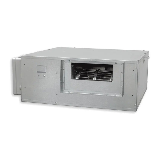
- Page 1 Air Handling Units Unità Trattamento Aria RNW 508-CS Horizontal ceiling dehumidifier Deumidificatore orizzontale a soffitto INSTALLATION / TECHNICAL MANUAL MANUALE INSTALLAZIONE / TECNICO...
-
Page 3: Avvertenze Generali
Il suo utilizzo è raccomandato, entro i limiti di funzionamento, in ambienti civili e/o del applications and/or commercial ones (e.g. offices). Any other different use MUST be agreed in advance with RDZ technical settore terziario (uffici, ...), per climatizzazione finalizzata department. -
Page 4: Avvertenze Per La Sicurezza
SAFETY WARNINGS | AVVERTENZE PER LA SICUREZZA Read this manual carefully before installing and/or using the Le g g e re co n at te n z i o n e q u e s to l i b re t to p r i m a equipment and keep it in an accessible place. -
Page 5: Smaltimento
DISPOSAL | SMALTIMENTO In accordance with the provisions of the following In base a quanto previsto dalle seguenti direttive European directives 2011/65/EU, 2012/19/EU and europee 2011/65/UE, 2012/19/UE e 2003/108/ 2003/108/EC, regarding reducing the use of CE, relative alla riduzione dell’uso di sostanze hazardous substances in electrical and electronic pericolose nelle apparecchiature elettriche ed equipment, in addition to waste disposal. -
Page 6: Table Of Contents
INDEX | INDICE Description Descrizione GENERAL WARNINGS AVVERTENZE GENERALI SAFETY WARNINGS AVVERTENZE PER LA SICUREZZA DISPOSAL SMALTIMENTO PRELIMINARY OPERATIONS OPERAZIONI PRELIMINARI GENERAL OVERVIEW PANORAMICA GENERALE Description Descrizione Machine Components Componenti Apparecchiatura Package Content Contenuto Imballo Complements Complementi Safety checks Controlli di sicurezza Components Componenti INSTALLATION... -
Page 7: Operazioni Preliminari
PRELIMINARY OPERATIONS | OPERAZIONI PRELIMINARI INSPECTION, TRANSPORT AND UNPACKING ISPEZIONE, TRASPORTO E DISIMBALLO On receipt immediately verify the integrity of the packaging; All’atto del ricevimento verificare immediatamente l’integrità the machine left the factory in perfect condition, any damage dell’imballo: la macchina ha lasciato la fabbrica in perfetto must immediately be contested with the carrier and noted on the stato, eventuali danni dovranno essere immediatamente Delivery Sheet before countersigning. -
Page 8: Panoramica Generale
1 GENERAL OVERVIEW | PANORAMICA GENERALE 1.1 DESCRIPTION | DESCRIZIONE Deumidificatore isotermico canalizzabile con integrazione estiva e Ductable isothermal dehumidifier with summer and winter integration invernale previsto per l’installazione orizzontale in controsoffitto. for horizontal ceiling installation. It consists in a complete cooling unit È... - Page 9 IMMISSIONE ARIA RICIRCOLO ARIA SUPPLY AIR RECIRCULATION AIR Hydraulic connections 1/2 "F Ø 20 mm Condensation Drain Scarico Condensa Ø 20 mm Attacchi idraulici 1/2”F AIR FILTERS - FILTRI ARIA Wiring Box e(PM10) min ≤50 % Quadro Elettrico coarse Hairs - Peli, capelli coarse...
-
Page 10: Contenuto Imballo
SF-P Condensate drain kit with casing, designed for wall installation. It can be used in combination with RDZ air handling units, and it is suitable for Ø 20-32 mm piping. The external shell can be adjusted considering the thickness of the wall. Washable Internal Cartridge. -
Page 11: Controlli Di Sicurezza
1.5 SAFETY CHECKS | CONTROLLI DI SICUREZZA All the control devices are tested in the factory before the equipment Tutti i dispositivi di controllo sono collaudati in fabbrica prima is shipped. Their operation is described in the following paragraphs. della spedizione dell’apparecchiatura. La loro funzionalità viene descritta nei paragrafi successivi. -
Page 12: Installazione
2 INSTALLATION - INSTALLAZIONE CAUTION ATTENZIONE L’installazione e la manutenzione Installation and maintenance must be carried out by vanno eseguiti solo da personale qualificato. qualified personnel only. Throughout installation, make sure Durante tutte le procedure di installazione, assicurarsi che that the equipment is not connected to the electrical mains. l’apparecchiatura non sia collegata alla rete elettrica. - Page 13 Duct work Canalizzazione Fixing to ceiling Fissaggio a so tto ø8mm [mm] Rubber mounts Gommino antivibrante Washer Rondella...
-
Page 14: Collegamenti Idraulici
min. min. 10 cm 30 cm Trap door Botola d’ispezione 2.2 HYDRAULIC CONNECTIONS | COLLEGAMENTI IDRAULICI Rif. Description Descrizione Pre-treatment water inlet (1/2”F) with lockshield to adjust Ingresso acqua pre-trattam. (1/2”F) con detentore di regolazione flow rate It is recommended to install metering units portata Si consiglia di installare i relativi misuratori di portata to control the water flow rate. - Page 15 (SF-P / SF-M 20). According to kit di scarico condensa RDZ disponibili (SF-P / SF-M the model chosen, respect the installation instructions 20). Rispettare, in base al modello scelto, le given below.
- Page 16 SF-P Cod. Condensate drain kit with casing, designed for wall installation. It can be used in combination with RDZ air handling units, and it is suitable for Ø 20-32 mm piping. The external shell can be adjusted considering the thickness of the wall. Washable Internal Cartridge. For information see the dedicated technical sheet.
- Page 17 RDZ air handling units. 3600400 Kit di scarico condensa composto da sifone con membrana in silicone, tubo e raccordo, da utilizzare in abbinamento alle unità di trattamento dell’aria RDZ. NOTE AGGIUNTIVE PER INSTALLAZIONE KIT SCARICO RDZ ADDITIONAL NOTES FOR RDZ DRAIN KIT INSTALLATION •...
- Page 18 HYDRAULIC CONNECTION ALLACCIAMENTO IDRAULICO Hydraulic connection to a refrigerating unit capable L’allacciamento idraulico ad un gruppo frigo in grado of supplying chilled water is indispensable. In this case, di fornire acqua refrigerata risulta indispensabile. the dehumidifier can operate without varying the temperature In tale caso il deumidificatore potrà...
-
Page 19: Collegamenti Elettrici
2.3 ELECTRICAL CONNECTIONS | COLLEGAMENTI ELETTRICI The dehumidifier must be connected to a sectional Il deumidificatore deve essere collegato ad una electrical outlet provided with an earthing connection. The presa di corrente sezionata provvista di terra. L’impianto electrical power system must be protected against overloads, elettrico di alimentazione deve essere protetto contro i sovraccarichi, i cortocircuiti, i contatti diretti ed indiretti, short circuits, direct or indirect contacts, in accordance with... - Page 20 Table D - Electrical connections to be made Tabella D - Collegamenti elettrici da effettuare Connections Collegamenti Alimentazione elettrica 230 V - 50Hz cavo 3x1,5 mm² Electrical power supply 230 V - 50Hz Cable 3x1,5 mm² ID1 Terminals morsetti ID1 Ventilation Consent Consenso Ventilazione cavo 2x1,5 mm²...
- Page 21 VENTILATION CONSENT CONSENSO VENTILAZIONE Two terminals are available on the dehumidifier circuit board Sono disponibili sulla scheda elettronica di controllo del which allow the unit to be operated in ventilation mode only. deumidificatore due morsetti che permettono di far funzionare The closure of the “ventilation consent”...
-
Page 22: Avviamento E Collaudo
3 START-UP AND TESTING - AVVIAMENTO E COLLAUDO The testing of the dehumidifier should be made at the same time collaudo deumidificatore andrebbe effettuato as that of the summer panel system; the main item to be made contestualmente a quello dell’impianto a pannelli in regards the cooling water flow rate, which varies depending on funzionamento estivo;... -
Page 23: Funzionamento
4 FUNCTIONING - FUNZIONAMENTO The machine is running when power is “on” and the dehumidification La macchina è in funzione quando viene data tensione consent is closed (see chap. “Electrical connections”). all’alimentazione ed il consenso deumidificazione è chiuso In any start-up the fan is first started and only after a certain delay, (vedere cap. -
Page 24: Allarmi
5 ALARMS - ALLARMI siGnals anD alarMs | segnalazioni e allarmi VISUAL SIGNALS SEGNALAZIONI VISIVE “POWER” red led: Led “POWER” rosso: if there is voltage, the led is on; se è presente la tensione è acceso fisso; “COMPR” green led: Led “COMPR”... -
Page 25: Guasti
FaulTs | gUasTi Table F - Troubleshooting Tabella F - Ricerca guasti Problem / Problema Cause / Causa Remedy / Rimedio No electrical power Connect the unit to the electrical power supply Mancanza dell’alimentazione elettrica Collegare l’unità all’alimentazione elettrica Line switch open Close the line switch Interruttore di linea aperto Chiudere l’interruttore di linea... -
Page 26: Manutenzione Ordinaria
È consentito pulire i filtri a vapore. After 3 consecutive cleaning operations, filter must be replaced. Dopo un ciclo di 3 pulizie consecutive il filtro deve essere Contact RDZ to purchase new filters. sostituito. Contattare RDZ per l’acquisto di nuovi filtri. OFF! Spento! every 90 days... -
Page 27: Manutenzione Straordinaria
6.2 EXTRAORDINARY MAINTENANCE / MANUTENZIONE STRAORDINARIA REMOVING THE FAN RIMOZIONE VENTILATORE Caution! To replace the fan you must remove the lower dehumidifier Attenzione! La sostituzione del ventilatore avviene rimuovendo panel. il pannello inferiore del deumifìdificatore. OFF! Spento! -
Page 28: Dati Tecnici E Prestazioni
7 TECHNICAL DATA AND PERFORMANCE - DATI TECNICI E PRESTAZIONI 7.1 DIMENSIONS AND TECHNICAL DATA / DIMENSIONI E DATI TECNICI [mm] Table G – technical characteristics Tabella G - Caratteristiche tecniche Technical specifications Specifiche tecniche l/day Condensed humidity Umidità condensata (26°C - 65%) l/giorno Nominal electrical power Potenza elettrica nominale... -
Page 29: Caratteristiche Acustiche
7.2 ACOUSTIC CHARACTERISTICS / CARATTERISTICHE ACUSTICHE The presence of canalisation and/or plenums further reduces La presenza della canalizzazione e/o plenum riduce the sound pressure level measured. The sound pressure levels ulteriormente il valore del livello di pressione of the equipment were measured in a reverberation chamber sonora rilevato. -
Page 30: Limiti Di Funzionamento
7.3 OPERATING LIMITS / LIMITI DI FUNZIONAMENTO The graphs shown below describe the operating range of the unit. I grafici sottoriportati descrivono il campo operativo dell’unità. La The maximum permitted temperature of the water for operation massima temperatura dell’acqua ammessa nel funzionamento in summer mode is 25 °C. -
Page 31: Prestazioni
7.4 PERFORMANCE / PRESTAZIONI Total refrigerating power (reserved to dehumidifier Potenza frigorifera totale (da riservare alle batterie di pretrattamento e postrattamento del deumidificatore) e pre-treatment and post-treatment batteries) to the resa in deumidificazione, in funzione della temperatura dehumidification yield, depending on the ambient ambiente, dell’umidità... - Page 32 Table L – Summer mode Tabella L- Caso estivo Functioning with ventilation mode only - Funzionamento in sola ventilazione Room Relative Inflow Water Water Flow on Water Flow on Sensible Latent Power Cooling Power Condensation on Cooling Power Condensation on Temperature Humidity Temperature...
-
Page 33: Curve Caratteristiche
7.5 CHARACTERISTIC CURVES | CURVE CARATTERISTICHE The figure below shows the curves of the prevalence available to La figura sottostante riporta le curve della prevalenza disponibile al ventilatore dell’apparrecchiatura. L’eventuale the ventilator of the apparatus. The ductwork of the dehumidifier canalizzazione del deumidificatore deve essere dimensionata must be sized according to this parameter. -
Page 34: Perdita Di Carico Circuito Idraulico
7.6 PRESSURE LOSS OF THE HYDRAULIC CIRCUIT | PERDITA DI CARICO CIRCUITO IDRAULICO The two curves represented in the diagram below indicate the Le due curve rappresentate nel diagramma sottostante indicano le perdite di carico sulle batterie ad acqua di pretrattamento e pressure drop on the battery to the water of pre-treatment and postrattamento dell’aria nel deumidificatore. - Page 36 FAG0CA011AB.01 10/2021...
Need help?
Do you have a question about the RNW 508-CS and is the answer not in the manual?
Questions and answers