Table of Contents
Advertisement
Quick Links
Advertisement
Table of Contents

Related Manuals for REMKO BL Series


Summary of Contents for REMKO BL Series
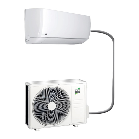
- Page 1 Operating and installation instructions REMKO BL series Inverter wall - room air conditioner in split design with quick- release coupling system BL 264 DC, BL 354 DC 0316-2022-07 Edition 1, en_GB Read the instructions prior to performing any task!
- Page 2 Read these operating instructions carefully before commis- sioning / using this device! These instructions are an integral part of the system and must always be kept near or on the device. Subject to modifications; No liability accepted for errors or mis- Refrigerant prints! Translation of the original...
-
Page 3: Table Of Contents
Table of contents Safety and usage instructions......................5 1.1 General safety notes........................5 1.2 Identification of notes........................5 1.3 Personnel qualifications........................5 1.4 Dangers of failure to observe the safety notes................5 1.5 Safety-conscious working....................... 6 1.6 Safety instructions for the operator....................6 1.7 Safety notes for installation, maintenance and inspection ............. - Page 4 REMKO BL series Care and maintenance........................43 Shutdown............................. 45 Spare parts list and exploded view....................46 Index..............................47...
-
Page 5: Safety And Usage Instructions
Safety and usage instructions DANGER! This combination of symbol and signal word 1.1 General safety notes warns of a situation in which there is immediate danger, which if not avoided may be fatal or Carefully read the operating manual before com- cause serious injury. -
Page 6: Safety-Conscious Working
REMKO BL series In particular, failure to observe the safety notes All housing parts and unit openings, e.g. air may pose the following risks: inlets and outlets, must be kept clear. The units must be inspected by a service tech- The failure of important unit functions. -
Page 7: Unauthorised Modification And Changes
"certificate of warranty" to The setup, connection and operation of the REMKO GmbH & Co. KG at the time when the units and its components must be undertaken units are purchased and commissioned. -
Page 8: Environmental Protection And Recycling
REMKO BL series 1.12 Environmental protection and recycling Disposal of packaging All products are packed for transport in environ- mentally friendly materials. Make a valuable contri- bution to reducing waste and sustaining raw mate- rials. Only dispose of packaging at approved collection points. -
Page 9: Technical Data
Technical data 2.1 Unit data Series BL 264 DC BL 354 DC Inverter wall-mounted room air conditioning unit Operating mode combination for cooling and heating 2.7 (0.6-3.8) 3.5 (0.8-4.1) Nominal cooling output Energy efficiency ratio SEER 6.20 6.19 El. power consumption, cooling 0.8 (0.1-1.6) 1.18 (0.1-1.6) El. - Page 10 REMKO BL series Data specific to indoor unit BL 264 DC IT BL 354 DC IT Application area (room volume), approx. Adjustment range, room temperature °C +17 to +30 Air flow volume per stage 400/500/600 dB (A) 29/35/42 28/31/41 Sound pressure level per stage...
-
Page 11: Unit Dimensions
2.2 Unit dimensions Outdoor units Fig. 1: Outdoor unit dimensions BL 264-354 DC AT Measurements (mm) BL 264-354 DC AT Indoor units Fig. 2: Indoor unit dimensions BL 264-354 DC IT Measurements (mm) BL 264-354 DC IT We reserve the right to modify the dimensions and design as part of the ongoing technical development process. -
Page 12: Design And Function
Design and function Unit description The BL 264-354 DC room air conditioners have a REMKO BL...AT outdoor unit as well as a BL...IT indoor unit. In cooling mode, the outdoor unit serves to output the heat extracted by the indoor unit from the room being cooled. -
Page 13: Operation
Operation 4.1 General notes The indoor unit is easily operated using the standard infrared remote control. The indoor unit beeps to acknowledge the correct transmission of data. If it is not possible to program the indoor unit with the remote control, then it can also be man- ually operated. -
Page 14: Display On Indoor Unit
REMKO BL series 4.2 Display on indoor unit "ON/OFF" key (ON/OFF) This key switches the room air conditioner on and The display illuminates according to the settings. off. "MODE" key (operating mode) This key is used to set the desired operating mode. - Page 15 Anti-F HEALT This function is not available. Using this key, the REMKO BioClean function (ioni- iCLEAN (self-cleaning) sation) can be activated which contributes to improving the room air quality. Due to the formation of condensate on the heat...
- Page 16 REMKO BL series Indicators on the LCD Fig. 9: Indicators on the LCD This symbol appears when the "ON/OFF" key is pressed and the system is activated. Pressing this key again causes the indicator to go out. Key lockIs displayed if key lock is activated.
-
Page 17: Installation Instructions For Qualified Personnel
Installation instructions for qualified personnel 5.1 Important notes prior to instal- 5.2 Wall openings lation A wall opening of at least 65 mm diameter and 10mm incline from the inside to the outside Transport the unit in its original packaging as must be created. -
Page 18: Selection Of Installation Location
REMKO BL series 5.4 Selection of installation Wind location If the unit is being installed in windy areas, ensure that the warm outlet air is discharged in the pre- Indoor unit vailing wind direction. If this is not the possible, it... -
Page 19: Minimum Clearances
Fig. 13: Installation inside buildings K: Cold fresh air / W: Warm air 3: Air shaft 1: Outdoor unit / 2: Additional fan 5.5 Minimum clearances Observe the minimum clearances to allow access for maintenance and repair work and facilitate optimum air distribution. -
Page 20: Connection Variants For The Indoor Unit
REMKO BL series 5.6 Connection variants for the indoor unit The following connection variants can be used for the refrigerant, condensate and control lines. Fig. 15: Connection variant (view from the rear) A: Infeed of the refrigerant piping at the wall, left... -
Page 21: Wall Bracket For The Indoor Unit
5.7 Wall bracket for the indoor unit Fig. 16: Mounting points for the wall bracket BL 264-354 DC IT (rear view, all dimensions in mm) Unit type / dimen- sions BL 264-354 DC IT (All dimensions in mm) The diameter of the pipe break-through is 65 mm for all unit types. The wall bracket for the units must be attached with suitable screws and anchors. -
Page 22: Connection Of Refrigerant Piping
REMKO BL series 6.2 Connection of 6.3 Connection of refrigerant piping quick-release couplings The refrigerant pipes should be connected by the The refrigerant pipes should be connected by the customer on the right-hand side of the outdoor customer on the right-hand side of the outdoor component. - Page 23 Fig. 21: Remove protective caps Before connecting the refrigerant pipes, ensure that the quick-release couplings are situated in front of one another (Fig. 22). Fig. 24: Tightening the fitting 1: Tighten with the first open-ended spanner 2: Counter with the second open-ended spanner Open the stop cocks with an Allen key before switch the system on! Pipe dimension...
-
Page 24: Leak Testing
REMKO BL series 6.4 Leak testing Condensate drainage connection and safe Once all the connections have been made, the pressure gauge station is attached to the Schrader drainage valve as follows (if fitted): red = small valve = high pressure... - Page 25 Safe drainage in the event of leakages For the designations of 1,3,5,8,9 and 11, please refer to the legend for Fig. 25 The REMKO oil separator OA 2.2 fulfils the fol- lowing list of requirements from regional regula- Dimensioning of the strip foundation tions and laws.
-
Page 26: Electrical Wiring
REMKO BL series Electrical wiring 8.1 General Information The control line to the outdoor unit contains a data cable which is used to establish communication A protected power supply cable is to be connected between the indoor unit and the outdoor unit. This... -
Page 27: Outdoor Unit Connection
8.3 Outdoor unit connection Fix the line in the strain relief and re- assemble the unit. Proceed as follows to connect the line: Remove the side-panel cover. Choose the cable cross-section in accord- ance with the relevant specifications. Connect the lines as shown on the electrical connection diagram. - Page 28 REMKO BL series Connection of optional condensate pump KP 6/KP 8 230 V/1~/50 Hz Fig. 31: Electrical wiring diagram Outdoor unit Condensate pump supply Indoor unit Condensate pump fault contact KP6/KP8 condensate pump BK: black Power supply cable WH: white...
-
Page 29: Electrical Drawings
8.5 Electrical drawings Indoor units BL 264-354 DC IT YE/GN Fig. 32: Electrical drawings A: Indoor unit control board 5: Not available B: Indoor unit connection block 6: Ion generator 1: Fan motor 7: Transformer 2: Wi-Fi connection 8: Probe, evaporator 3: Display circuit board 9: Room temperature probe 4: Horizontal swing motor... - Page 30 REMKO BL series Outdoor units BL 264-354 DC AT YE/GN YE/GN Fig. 33: Electrical drawings A: Control board, outdoor unit 3: 4-way changeover valve B: Outdoor unit connection block 4: Heating element C: Control line to indoor unit 5: Sensors...
-
Page 31: Before Commissioning
Before commissioning Commissioning Perform the following checks prior to putting the unit into operation for the first time and after any NOTICE! work on the cooling cycle. Record the results in the commissioning report: Commissioning should only be performed by specially trained personnel and documented Check all refrigerant piping and valves for leak- after the certificate has been issued. - Page 32 REMKO BL series Function test of the cooling and heating modes Remove the protective caps from the valves. Start the commissioning procedure by briefly opening the shut-off valves on the outdoor unit until the pressure gauge indicates a pressure of approx. 2 bar.
-
Page 33: Troubleshooting And Customer Service
Troubleshooting and customer service 11.1 Troubleshooting and customer service The unit and components are manufactured using state-of-the-art production methods and tested several times to verify that they function correctly. However, if malfunctions do occur, please check the functions as detailed in the list below. For systems with an indoor unit and outdoor unit, refer to the chapter "Trouble- shooting and customer service"... - Page 34 REMKO BL series Malfunction Possible causes Checks Remedial measures Windows and doors Have structural/usage Close windows and open. Heating/cooling modifications been doors/install additional load has increased made? units Cooling mode is not set Does the cooling symbol Correct the settings for...
- Page 35 Fault display on the indoor unit Display Error description Indoor unit overcurrent protection Ambient air probe fault Outdoor unit heat exchanger probe fault Indoor unit heat exchanger probe fault Fan speed control indoor unit disabled E5 (5E) Communication error between indoor unit and outdoor unit EEPROM error, indoor unit Fan speed control outdoor unit disabled Power module protective function triggered...
-
Page 36: Indoor Unit Fault Analysis
REMKO BL series 11.2 Indoor unit fault analysis Fault E0: Indoor unit overcurrent protection Check whether the power supply is present Switch the supply and try again as soon as and correct. Is this normal? this is normal again. Check all electrical connections. Are they Correct the electrical connections. - Page 37 Fault E4: Indoor unit fan speed disabled Check the connection of the fan motor to the Establish a proper connection. circuit board. Is this correctly implemented? Measure the voltage between the yellow and black cable when starting the air-conditioning Replace the indoor unit control board. system.
- Page 38 REMKO BL series Fault F0: Fan speed control outdoor unit disabled Is the fan motor blocked by a foreign body Remove foreign body. Check all electrical connections. Are these Replace the connections. correctly implemented? Replace the outdoor unit circuit board. Is the Error rectified.
- Page 39 Fault F3: Overcurrent protection on the compressor Check all electrical connections. Are these Replace the connections. correctly implemented? Check the compressor windings. Are they Replace the compressor. Exchange the control boards of the outdoor unit Fault F4: Compressor outlet probe fault Check the connection of the respective probe to the circuit board.
- Page 40 REMKO BL series Fault F6: Outdoor unit air inlet probe fault Check the connection of the respective probe to the circuit board. Are these correctly imple- Establish a proper connection. mented? Check the resistance of the probe. Is the Replace the probe.
- Page 41 Fault P2: High pressure fault Check the heat exchanger of the outdoor unit and indoor unit. Are the heat exchangers Clean the heat exchangers. clean? Are the corner shut-off valves open? Open corner shut-off valves Refrigerant cannot circulate. Possibly due to internal contamination or kinked lines.
- Page 42 REMKO BL series Fault P5: Compressor outlet probe overtemperature Check the heater exchanger of the outdoor Clean the heat exchangers. unit. Is the heat exchanger clean? Rectify the leak. Adjust the refrigerant quan- Is there a lack of refrigerant? tity.
-
Page 43: Care And Maintenance
Care and maintenance Maintenance It is recommended that you take out a mainte- Regular care and observation of some basic points nance contract with an annual service from an will ensure trouble-free operation and a long appropriate specialist firm. service life. DANGER! This enables you to ensure the operational reli- Prior to performing any work, ensure the equip-... - Page 44 REMKO BL series Cleaning the housing Disconnect the power supply to the unit. Open and fold the air inlet grill on the front side upwards. Clean the grill and cover with a soft, damp cloth. Switch the power supply back on.
-
Page 45: Shutdown
Ensure that units and components are disposed of in accordance with local regulations, e.g. through authorised disposal and recycling specialists or at collection points. REMKO GmbH & Co. KG or your contractual partner will be pleased to provide a list of certified firms in your area. -
Page 46: Spare Parts List And Exploded View
REMKO BL series Spare parts list and exploded view The continuous further development of REMKO products sometimes involve adjustments to spare parts within a unit series which are linked to each production batch. To ensure the correct delivery of spare parts, unit series number information is therefore required (see name plate). -
Page 47: Index
Index Care and maintenance ....43 Propellant in accordance with Kyoto Protocol . . 10 Cleaning Air filter for indoor unit ....44 Condensate pump . - Page 48 REMKO QUALITY WITH SYSTEMS Air-Conditioning | Heating | New Energies Telephone +49 (0) 5232 606-0 REMKO GmbH & Co. KG Hotline within Germany +49 (0) 5232 606-0 Klima- und Wärmetechnik Telefax +49 (0) 5232 606-260 Im Seelenkamp 12 E-mail info@remko.de...
Need help?
Do you have a question about the BL Series and is the answer not in the manual?
Questions and answers