Table of Contents
Advertisement
M O B I L E
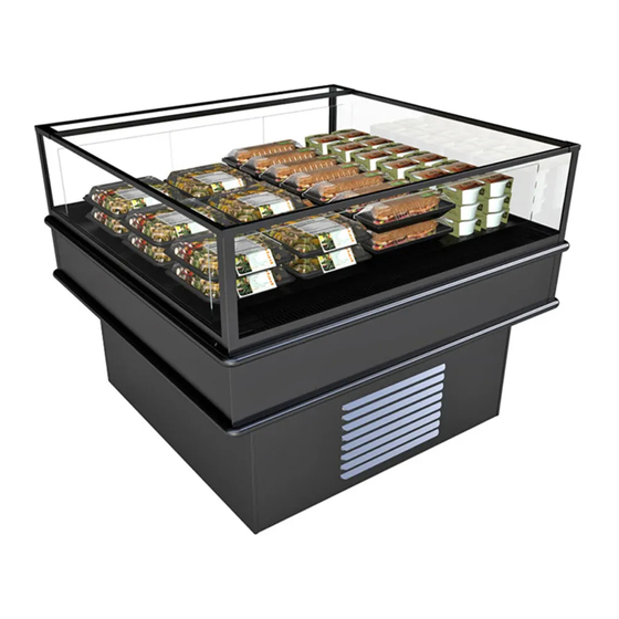
SELF-SERVICE MULTI-PURPOSE FREEZER-REFRIGERATED
ISLAND DISPLAY CASES
Oper Manual\21-34184_QR_MIXXRF_User Manual_Mobile Island Freezer-Refrig Case.pub
READ AND SAVE THESE INSTRUCTIONS
INSTALLATION &
OPERATING MANUAL
S E R I E
MI46RF
888 E. Porter Road ∙ Muskegon, MI 49441
Phone: 231.798.8888 Fax: 231.798.4960 www.structuralconcepts.com
MI44RF
Important!
See Page 7 For 3-Way
Temperature Switch
Instructions.
See Page 13 For
Product And Signage
Placement Guidelines.
MI48RF
P/N 21-34184
Rev E Date: 1.13.2022
Advertisement
Table of Contents
Troubleshooting

Subscribe to Our Youtube Channel
Related Manuals for Structural Concepts Oasis MI44RF


Summary of Contents for Structural Concepts Oasis MI44RF
- Page 1 READ AND SAVE THESE INSTRUCTIONS Important! INSTALLATION & See Page 7 For 3-Way OPERATING MANUAL Temperature Switch M O B I L E S E R I E Instructions. SELF-SERVICE MULTI-PURPOSE FREEZER-REFRIGERATED See Page 13 For ISLAND DISPLAY CASES Product And Signage Placement Guidelines.
-
Page 2: Table Of Contents
TABLE OF CONTENTS OVERVIEW / TYPE / COMPLIANCE / WARNINGS / PRECAUTIONS / WIRING / PLUGS .....….. CASE REMOVAL FROM SKID (LOCKING/UNLOCKING CASTERS) ……………………..………….….. CASTER LOCKING AND EXTERIOR PANEL ATTACHMENT (AFTER REMOVAL FROM SKID) ..….. CASE START-UP VIA MAIN POWER SWITCH / TEMPERATURE CONTROL 3-WAY SWITCH ...….. HONEYCOMB AIR DIFFUSER ………………………………………………..………………………………. -
Page 3: Overview / Type / Compliance / Warnings / Precautions / Wiring / Plugs - Page 1 Of 2
OVERVIEW Performance issues when in violation of applicable NEC, These Structural Concepts cases are designed to federal, state and local electrical and plumbing codes are merchandise product at 3 separate temperature settings: not covered by warranty. See below. - Page 4 OVERVIEW / TYPE / COMPLIANCE / WARNINGS / PRECAUTIONS / WIRING / PLUGS - PAGE 2 of 2 PRECAUTIONS WIRING DIAGRAM This sheet contains important precautions to prevent Each case has its own wiring diagram folded and in damage to unit or merchandise.
-
Page 5: Case Removal From Skid (Locking/Unlocking Casters)
CASE REMOVAL FROM SKID (LOCKING/UNLOCKING CASTERS) 1. Removing Case Shipping Brackets That Are Attached To Skid Remove screws holding shipping brackets to skid. Remove shipping brackets from skid. See illustrations below. Note: Shipping Brackets will vary in size, shape, material and location depending upon case type and model. -
Page 6: Caster Locking And Exterior Panel Attachment (After Removal From Skid)
CASTER LOCKING AND EXTERIOR PANEL ATTACHMENT (AFTER REMOVAL FROM SKID) All exterior panels may be removed without 3. Caster Locking / Unlocking Operation tools. To lock casters (from the unlocked position), press Lift exterior panel up and off tabs. down on each RAISED caster lever (as shown in ... -
Page 7: Case Start-Up Via Main Power Switch / Temperature Control 3-Way Switch
CASE START-UP VIA MAIN POWER SWITCH / TEMPERATURE CONTROL 3-WAY SWITCH 1. Display Case Start-Up B. Refrigerated packaged MEAT & DAIRY products at 38 °F (3.3 °C) or less product Remove front panel on control side of unit temperatures. (see illustration below). -
Page 8: Honeycomb Air Diffuser
HONEYCOMB AIR DIFFUSER Honeycomb Air Diffuser See PREVENTIVE MAINTENANCE (TO BE PERFORMED BY TRAINED SERVICE Honeycomb air diffuser is on all models. PROVIDERS) section in manual for cleaning Honeycomb may be removed for cleaning and/or specifics. maintenance. ... -
Page 9: Evaporator Section Access: Rack Wire Removal
EVAPORATOR SECTION ACCESS: RACK WIRE REMOVAL Caution! Turn Off Power To Unit Before Removing Deck Pans. Rotating Fans Can Cause Severe Injury! Evaporator Section Access 1. Rack Wire Removal Note: Illustration Shown May Rack wire allows product to be raised from deck surface. Not Exactly Reflect Every ... -
Page 10: Evaporator Section Access, Continued: Deck Pan Removal / Thermometer
EVAPORATOR SECTION ACCESS, CONTINUED: DECK PAN REMOVAL / THERMOMETER Caution! Turn Off Power To Unit Before Removing 3. Thermometer Deck Pans! Rotating Fans Can Cause Severe Injury! Thermometer is located on air return duct (as illustrated below). Evaporator Section Access ... -
Page 11: Evaporator Section Access, Continued: Evaporator Area Layout
EVAPORATOR SECTION ACCESS, CONTINUED: EVAPORATOR AREA LAYOUT Caution! Turn Off Power To Unit Before Removing Deck Pans! Rotating Fans Can Cause Severe Injury! Evaporator Section Access, Cont’d 4. Evaporator Section Layout After lower deck pans have been removed, you may access TXV, drain, refrigeration lines, trough & drain (as illustrated below). -
Page 12: Load Limit (Load Line) Guidelines / Case Front & Rear Designations
LOAD LIMIT (LOAD LINE) GUIDELINES / CASE FRONT & REAR DESIGNATIONS 1. Load Limit (Load Line) Guidelines Caution! Stacking food beyond the load line will prevent food from being at proper temperature. Load line is placed at location to allow proper refrigerated airflow to product. ... -
Page 13: Product And Signage Placement Guidelines
PRODUCT AND SIGNAGE PLACEMENT GUIDELINES Place low protein products (such as produce, sauces 1. Product Placement Guidelines and pastas closer to air return side of merchandiser). Higher protein products require the coolest air Note: NEVER set product on air return grille! temperatures on a case. -
Page 14: Condenser Package Slide-Out
CONDENSER PACKAGE SLIDE-OUT Condenser Package Slide-Out Note: Servicing to be accomplished by licensed electrical/refrigeration contractor. Pull Out Refrigeration Package Note: At initial slide-out, it may be necessary to remove compressor pan shipment screws (see illustration below for location). Plastic glides are mounted at base to assist in sliding the condenser out for access. -
Page 15: Condenser Package Exploded Pictorial - Model Mi44Rf.7448
CONDENSER PACKAGE EXPLODED PICTORIAL - MODEL MI44RF.7448 Illustration Below May Not Reflect Every Feature Or Option Of Your Particular Case. See Next Page For Alternate Condenser Package Designs. Condensing Coil (and Internal Fan) Compressor Electrical Box Compressor Drain Filter Dryer Sight Glass Hot Gas Loop Condensate... -
Page 16: Condenser Package Exploded Pictorial - Model Mi46Rf.7448 And Mi48Rf.7448
CONDENSER PACKAGE EXPLODED PICTORIAL - MODEL MI46RF.7448 AND MI48RF.7448 Illustration Below May Not Reflect Every Feature Or Option Of Your Particular Case. See Previous Page For Alternate Condenser Package Designs. Condensing Coil (and Internal Fans) Drain Condensate Overflow Pan Hot Gas Loop Condensate Pan / Wicking Material... -
Page 17: Serial Label Location & Information Listed / Tech Info & Service
For additional technical information and service, see the TECHNICAL SERVICE page in this manual for instructions on contacting Structural Concepts’ Technical Service Department. See images below for samples of both refrigerated and non-refrigerated serial labels. ... -
Page 18: Cleaning Schedule
CLEANING SCHEDULE (“D” = Daily / “W” = Weekly) Area/ Task Component Acrylic MUST BE cleaned according to these instructions to prevent acrylic surfaces from becoming cloudy, dull or scratched. DO NOT use a dry cloth or paper towel to wipe off dust or debris (this can rub dirt and dust into the acrylic surface). -
Page 19: Troubleshooting (General)
TROUBLESHOOTING (GENERAL) CONDITION TROUBLESHOOTING Water Is On The Floor Check that the drain trap is free of debris. Check that the drain hose is correctly positioned over evaporator pan (or floor drain, for remote units). Check store conditions. To prevent condensation in Type 1 environments, maximum conditions are to be 55% humidity / 75 °F. - Page 20 TROUBLESHOOTING, GENERAL - CONTINUED CONDITION TROUBLESHOOTING Fans Are Not Working, Continued Check that power is going to fan Check that fan wiring is connected on terminal blocks. System Is Not Operating Check that the utility power is on. Check the circuit breaker box for tripped circuits. Case Is Not Holding Temperature If a large amount of warm product was added to the case, it will take time for the temperature to adjust.
-
Page 21: Troubleshooting - Condensing System (Qualified Service Technicians)
TROUBLESHOOTING - CONDENSING SYSTEM (BY TRAINED SERVICE PROVIDERS ONLY) CONDITION TROUBLESHOOTING Head Pressure Too High Check that the condensing coil is not dirty or covered. Check that condensing fans are working. Check that refrigerant is not overcharged. Perform sub-cooling check and verify that no contaminates are in system. Check that liquid line filter dryer is not plugged. -
Page 22: Troubleshooting - Evaporator System (Qualified Service Technicians)
TROUBLESHOOTING - EVAPORATOR SYSTEM (BY TRAINED SERVICE PROVIDERS ONLY) CONDITION TROUBLESHOOTING Low Suction Pressure Check if sight glass is flashing or showing low charge. Check that expansion valve (TXV) isn’t restricted. Check element charge. Check that liquid line or filter isn’t restricted. Check that refrigeration lines and/or hoses are not kinked on either high or low sides. -
Page 23: Preventive Maintenance (Performed By Trained Service Provider)
PREVENTIVE MAINTENANCE (TO BE PERFORMED BY TRAINED SERVICE PROVIDER) WARNING! TURN OFF CASE BEFORE PERFORMING PREVENTIVE MAINTENANCE! Area of FREQ. INSTRUCTIONS Case Case Monthly Condensing Coil: Exterior Remove panel to access area by lifting up and off (no screw removal is required;... -
Page 24: Carel® Controller: Programming The Instrument
1 second. mute To Activate / Deactivate Auxiliary Output ▲ Press and hold the “aux” key for 1 second. This data derived from Carel® Controller Material: ir33 +030220441 - rel. 2.0 - 01.05.2006. Structural Concepts Document - Revision C Date: 1.4.2022... -
Page 25: Buzzer And Relay
Summary Table of Alarm and Signals: Display, Buzzer and Relay This data derived from Carel® Controller Material: ir33 +030220441 - rel. 2.0 - 01.05.2006. Structural Concepts Document - Revision C Date: 1.4.2022 reset alarms w/manual reset / reset HACCP alarms / reset temp. monitoring... -
Page 26: Carel® Controller: Summary Table Of Operating Parameters
This data derived from Carel® Controller Material: ** Case will go into defrost ONLY when case is turned off and then ir33 +030220441 - rel. 2.0 - 01.05.2006. back on when probe is reading below 45 °F. Structural Concepts Document - Revision C Date: 1.4.2022... -
Page 27: Controller
CAREL PROGRAMMABLE CONTROLLER, CONT’D Integrated Electronic Microprocessor Controller ▲ Changing “Meat & Dairy” and “Produce” mute Setpoints Using The Programmable Controller ▼ To Increase or Decrease the Value 9. To store the new parameters values, Press of the “Meat & Dairy” Temperature Setting: and hold “Prg”... -
Page 28: Technical Service Contact Information & Warranty Information
DAMAGE, STORE’S AMBIENT CONDITIONS, ETC.) LIMITED WARRANTY Overview: All sales by Structural Concepts Corporation (hereafter referred to as “SCC”) are subject to the following limited warranty. “Goods” refers to the product or products being sold by SCC. Warranty Scope: Warranty is for equipment sold in the United States, Canada, Mexico and Puerto Rico. Equipment sold elsewhere may carry modified warranties.
Need help?
Do you have a question about the Oasis MI44RF and is the answer not in the manual?
Questions and answers