Table of Contents
Advertisement
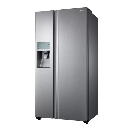
REFRIGERATOR
RH58K*
RS6500KC(RH62K)-FSR-160106.indd 1
REFRIGERATOR
SIDE BY SIDE TYPE
MODEL NAME : RH62K*, RH58K*
MODEL CODE : RH62K62817A/SC, RH62K6131S8/SC,
RH62K6287SL/ME, RH62K60177P/TL,'
RH62K62377A/ST, RH62K62377P/SV,
RH62K6217SL/SE, RH58K6467SL/TC,
RH58K6467SL/SE, RH58K6687SL/ST,
RH58K66877P/ME, RH58K6687SL/SV,
RH58K6317SL/CL, RH58K6317SL/ZS
1. PRECAUTIONS(SAFETY WARNINGS) · 5
2. PRODUCT SPECIFICATIONS ··············· 8
3. DISASSEMBLY AND REASSEMBLY······ 16
4. TROUBLESHOOTING ·························· 41
5. PCB DIAGRAM ····································· 76
6. WIRING DIAGRAM ······························· 82
7. BLOCK DIAGRAM ································ 86
RH62K*
8. MODEL CODE TABLE ························· 89
CONTENTS
2016. 1. 7.
11:03
Advertisement
Table of Contents


Need help?
Do you have a question about the RH62K Series and is the answer not in the manual?
Questions and answers