
Related Manuals for BRUEL & KJAER PULSE 7788


Summary of Contents for BRUEL & KJAER PULSE 7788
- Page 1 Technical Documentation PULSE Vehicle Pass‐by Systems based on Vehicle Pass‐by Software Type 7788 Installation Manual English BE 1716 – 14...
- Page 3 PULSE Vehicle Pass‐by Test Systems Installation Manual September 2015 BE 171614...
- Page 4 Safety Considerations This apparatus has been designed and tested in accordance with IEC/EN 61010 – 1 and ANSI/ Safety Requirements for Electrical Equipment for Measurement, Control and UL 61010 – 1 Laboratory Use . This manual contains information and warnings which must be followed to ensure safe operation and to retain the apparatus in safe condition.
-
Page 5: Table Of Contents
Contents CHAPTER 1 Introduction ........................ 1 System Overview ..........................1 System Operation ..........................2 How to Use this Manual ........................3 CHAPTER 2 Components for a Ground Station Only Configuration.......... 5 Ground Station Main Components ....................5 Ground Station Options and Accessories................... 7 CHAPTER 3 Installing a Ground Station Only Configuration............ 9 Install the Pass-by Software ......................9 Connect the Hardware ........................ - Page 6 Troubleshooting the Ground Station ..................38 Troubleshooting the Vehicle Station..................39 Troubleshooting the WLAN System ................... 40 Troubleshooting the Weather Station ..................41 Troubleshooting the 2-channel Telemetry System............... 43 CHAPTER 8 Quick Setup Guide ..................... 45 Configuring a Ground Station with Weather Station............45 Adding Telemetry to the Ground Station .................
-
Page 7: Chapter 1 Introduction
Chapter 1 Introduction System Overview PULSE Vehicle Pass-by systems are customizable PULSE systems with functionality provided by dedicated hardware and software specifically designed for pass-by measurements. The system is built around two basic units: • Ground Station • Vehicle Station Fig.1.1 Pass‐by system configuration In-vehicle Equipment GPS Satellite AUX 1 - 4... -
Page 8: System Operation
PULSE Vehicle Pass‐by Test Systems – Installation Manual Fig.1.1 shows an overview of a pass-by test system. The typical configuration is a multi- vehicle configuration using both the Ground Station and Vehicle Station to acquire and measure both pass-by and in-vehicle data. On the Ground Station, PULSE measures all acoustic channels, speed measurements and triggering signals. -
Page 9: How To Use This Manual
CHAPTER 1 Introduction 1.2.1 Multiple Vehicle Measurements It may be necessary to let several vehicle exterior noise tests run in parallel. In this case, a single Ground Station acquires the necessary acoustic and triggering reference data for all of the vehicles and the relevant run data is merged with the Vehicle Station for each specific vehicle. - Page 10 PULSE Vehicle Pass‐by Test Systems – Installation Manual...
-
Page 11: Components For A Ground Station Only Configuration
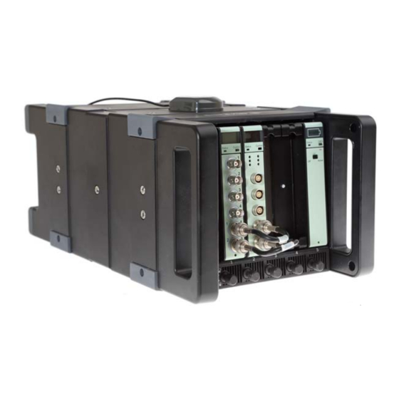
Chapter 2 Components for a Ground Station Only Configuration Ground Station Main Components The Ground Station includes the following front-end components: • LAN-XI Frame Type 3660-C-100 with GPS: Houses all front-end modules • LAN-XI 6-ch. Input Module Type 3050-A-060: Acquires data for the acoustic channels, ground-based speed sensor (radar) and triggering references (photocells) •... - Page 12 PULSE Vehicle Pass‐by Test Systems – Installation Manual Other standard items required by the Ground Station are shown in Table 2.1. Table 2.1 List of standard Ground Station components Component Description High-performance PC running Runs the Pass-by software ® Windows 7 or higher 2 Type 4189-A-021: Measures sound pressure level Prepolarized Microphone with preamplifier 2 ...
-
Page 13: Ground Station Options And Accessories
CHAPTER 2 Components for a Ground Station Only Configuration Ground Station Options and Accessories 2.2.1 Options The functionality of the pass-by system can be expanded to include a radar system for speed measurement, a weather station and a radio-based telemetry system that can transfer two channels of low frequency data such as: one engine speed and one vehicle speed (if a precision GPS is used for vehicle speed measurement) as TTL pulses. - Page 14 PULSE Vehicle Pass‐by Test Systems – Installation Manual Component Description WQ-3208: 2-channel Telemetry For systems where there is a need System, includes transmitter and for vehicle parameters such as receiver engine RPM, throttle position vehicle speed WQ-2410: Cigarette Lighter Power Allows power for both the Splitter telemetry system and in-vehicle sensor to be acquired from the...
-
Page 15: Installing A Ground Station Only Configuration
Chapter 3 Installing a Ground Station Only Configuration Standard A Ground Station only configuration is to be used with the mode in the Pass- by software. Please see Chapter 2 for pictures and descriptions of the items to be installed in this configuration. Install the Pass‐by Software If you have received a factory-installed system: 1) Connect the front end to the PC using the supplied LAN cable. -
Page 16: Connect The Hardware
PULSE Vehicle Pass‐by Test Systems – Installation Manual Connect the Hardware Fig.3.1 Typical setup with a Ground Station only configuration Reflector Radio Telemetry Photocell Mic. B Mic. A Weather Station (with PoE connection box) Radar and Tripod Operator PC Radio Telemetry Receiver Control Room AUX 1 - 4 AUX 5 - 8 140414 Ground Station Connect the Front End 1) Place the Ground Station in such a way as not to influence the free-field conditions required for a pass-by test. - Page 17 CHAPTER 3 Installing a Ground Station Only Configuration Fig.3.2 Pass‐by track layout with the PP’ line defined Measurement Stop Measurement Start Test Zone Approach Zone Mic. A CC´ Trigger 1 AA´ PP´ BB´ (Trigger 2) Mic. B 090021 2) Connect the photocell unit’s cable to a LEMO input on the front end’s Connection Module (see Fig.3.3).
- Page 18 PULSE Vehicle Pass‐by Test Systems – Installation Manual Mic B Mic A will be the microphone to the left of the start position (facing Mic B forwards), and will be the microphone to the right. 3) Arrange the mounted Microphones as required by the test standard in use. If this is a typical pass-by measurement, the front of the Microphone should be facing the centre line of the test track and placed 7.5 m (24.6 ft) from it.
- Page 19 CHAPTER 3 Installing a Ground Station Only Configuration 3) Aim the radar beam at the centre of the test zone (that is, the intersection of the test track’s centre line and the line 00´ connecting the Microphones). We recommend that you use the test vehicle (or another object) as a reference point during setup and that you aim the Radar Unit at this point.
- Page 20 PULSE Vehicle Pass‐by Test Systems – Installation Manual 4) Install the Weather Station’s driver software (Vaisala WXT 520), including GADI Driver Type 3099-E. This is necessary for the weather station to deliver data to the pass-by system. You can ensure that the driver is installed and running when the icon shown in Fig.3.7 is visible in the PC’s task bar.
-
Page 21: Components For A Multi-Vehicle Configuration
Chapter 4 Components for a Multi‐vehicle Configuration In this configuration, you will have two stations: the Ground Station and Vehicle Station. Both systems have PCs attached and communicate using WLAN. Additional Ground Station Components The Ground Station hardware is the same as what is listed in Chapter 2, with the exception of additional communication and synchronization accessories: Table 4.1 List of additional Ground Station components for running synchronized measurements... -
Page 22: Vehicle Station Main Components
PULSE Vehicle Pass‐by Test Systems – Installation Manual Vehicle Station Main Components The Vehicle Station includes the following front-end components: • LAN-XI Frame with GPS Type 3660-C-100: Houses all front-end modules • LAN-XI 6-ch. Input Module Type 3050-A-060: Acquires data in the vehicle. This data can be engine RPM from a tacho sensor, vehicle speed data from a precision GPS, or sound and vibration data. -
Page 23: Vehicle Station Options And Accessories
CHAPTER 4 Components for a Multi‐vehicle Configuration Table 4.2 List of standard Vehicle Station components Component Description High-performance PC running Runs the Pass-by software ® Windows 7 or higher WA-1772: LAN-XI Frame Provides eyelets to secure the Securing Fixture Vehicle Station’s front end within the vehicle WQ-3561: WLAN Antenna Vehicle Station WLAN hardware. WQ-3528: WLAN Wireless Radio Provides wireless transmission of WQ-3532: WLAN PoE Adapter... - Page 24 PULSE Vehicle Pass‐by Test Systems – Installation Manual Component Description WQ-2350: Cigarette Lighter Tacho Measures engine speed using the Sensor alternator ripple seen on the 12- volt vehicle bus. May not work on all vehicles MM-0097: Throttle Position Measures throttle position Sensor WQ-2410: Cigarette Lighter Power Provides power outlets for two Splitter units for use with the cigarette...
-
Page 25: Installing A Multi-Vehicle Configuration
Chapter 5 Installing a Multi‐vehicle Configuration Multivehicle A Multi-vehicle configuration is to be used with the mode in the Pass-by software. Please see Chapter 4 for pictures and descriptions of the in-vehicle items to be installed in this configuration. Multi‐vehicle Operation Overview Fig.5.1 Typical multi‐vehicle system configuration In-vehicle Equipment GPS Satellite AUX 1 - 4 Throttle... - Page 26 PULSE Vehicle Pass‐by Test Systems – Installation Manual Note: The Ground Station runs continuously and measures the acoustic signals, photocell signals, radar and weather station data, if present. This information is continuously broadcast to the Vehicle Station using a remote station server and client to manage the data transfer.
-
Page 27: Install The Pass-By Software
CHAPTER 5 Installing a Multi‐vehicle Configuration Fig.5.3 The PBY Ground Station software module during operation Data is acquired and uploaded from the Ground Station PC to the Vehicle Station PC at the end of the run and synchronized with the data measured by the Vehicle Station. This is done using GPS-based time stamping (universal time clock). The complete results for the pass-by run are then presented directly after each run on the Vehicle Station PC, where they are stored. - Page 28 PULSE Vehicle Pass‐by Test Systems – Installation Manual 2) Install the PULSE software on your PC, including GADI Driver Type 3099-E if using a weather station. 3) Once PULSE is installed, run the Front-end Setup program found under Programs\PULSE\Applications\Front-end Setup follow on-screen instructions on how to connect and configure LAN-XI hardware. 4) If there is no PULSE license installed on your system, follow the instructions given in the PULSE License Installation manual, BE 1693.
-
Page 29: Connect The Hardware
CHAPTER 5 Installing a Multi‐vehicle Configuration Connect the Hardware For instructions on connecting the Ground Station hardware, see Chapter 3. Connect the GPS Antennae Both the Ground Station and Vehicle Station must install the included GPS Antenna. 1) Place each GPS Antenna on a horizontal surface with an unobstructed view of the sky. - Page 30 PULSE Vehicle Pass‐by Test Systems – Installation Manual 2) Mount the Vehicle Station onto the front passenger seat using the Frame Securing Fixture and some bungee cords or straps. 3) Connect the PC to the front end’s frame using one of the LAN cables. Fig.5.6 Connecting the LAN cable to ...
- Page 31 CHAPTER 5 Installing a Multi‐vehicle Configuration Fig.5.7 GPS speed sensor with connection cables attached Connect a Vehicle‐mounted Photocell The Vehicle Station can be triggered using a vehicle-mounted photocell. This relieves the driver of the task of starting the measurement for each run. The Vehicle-mounted Photocell is designed to be attached to a standard vehicle number plate with straps or tape (see Fig.5.8).
-
Page 32: Setting Up For Data Transfer
PULSE Vehicle Pass‐by Test Systems – Installation Manual Setting Up for Data Transfer Data transfers are performed using WLAN. To learn more about configuring the WLAN system please read Chapter 6. Fig.5.9 The Vehicle Station WLAN hardware with: WLAN antenna, wireless radio (Bullet™) and PoE adapter 1) Connect the WLAN system’s PoE adapter to the wireless radio. Warning!: The wireless radio runs on 24 volts DC. The radio will be damaged irreparably by the 48 volts PoE from the front end if connected directly without the PoE adapter in between. - Page 33 CHAPTER 5 Installing a Multi‐vehicle Configuration Fig.5.10 Connecting the LAN cable to the front end Connect the LAN cable to the LAN socket 4) Switch the PoE output to the socket used. 5) The base of the WLAN antenna is magnetic. Mount it securely on the roof or an appropriate external surface of the vehicle. The antenna must be mounted vertically. 6) Ensure that the WLAN unit is securely mounted within the vehicle.
- Page 34 PULSE Vehicle Pass‐by Test Systems – Installation Manual Fig.5.12 Switching on the front end Use the switch to power the Vehicle Station...
-
Page 35: Wireless Lan Configuration
Chapter 6 Wireless LAN Configuration Wireless LAN (WLAN) Hardware ® The recommended WLAN system for the pass-by system is based on the Ubiquiti family of high performance WLAN units. These units benefit from using PoE which means that they can be connected to, and powered directly from the front end with a simple Ethernet Cat 6 cable. -
Page 36: Installation And Configuration
PULSE Vehicle Pass‐by Test Systems – Installation Manual Installation and Configuration The usual precautions pertaining to operating radio equipment must be observed. As this is WLAN, no special licenses are needed but connection quality tests need to be carried out to ensure a good quality signal. Mesh/chainlink fencing and the presence of other radio frequency emitting devices can impact connection quality. - Page 37 CHAPTER 6 Wireless LAN Configuration Fig.6.1 Connecting the LAN cable to Connect the LAN the front end cable to the LAN socket 4) Connect the Ground Station PC to the other LAN port on the front end frame. 5) Configure the PC’s Ethernet LAN card: a) Go to Start, Control Panel, Network and Sharing Center. b) From the available connections, select the LAN-XI frame connection.
- Page 38 PULSE Vehicle Pass‐by Test Systems – Installation Manual Fig.6.2 Settings for the Ground Station WLAN hardware (base station) 9) As the signal broadcast power should not exceed the legally defined limits for the region in which the system is operating, you must take into account the gain of the antenna used and the output power setting. Frequency List Click the Enable checkbox next to and then the Edit button to open...
- Page 39 CHAPTER 6 Wireless LAN Configuration Management IP Address c) Set the to Static. 11) You can now enter an IP address in line with the those given in Table 6.1 or according to your own IT policy. Table 6.2 Parameter Value Summary of suggested Wireless Mode Access Point settings for the Ground...
- Page 40 PULSE Vehicle Pass‐by Test Systems – Installation Manual Fig.6.4 Connecting the LAN cable to Connect the LAN the front end cable to the LAN socket 3) Switch the PoE output to the socket used. 4) The base of the WLAN antenna is magnetic. Mount it securely on the roof or an appropriate external surface of the vehicle. The antenna must be mounted vertically. 5) Ensure that the WLAN unit is securely mounted within the vehicle.
-
Page 41: Surveying A Site For Wlan Operation
CHAPTER 6 Wireless LAN Configuration The installation and configuration of the Vehicle Station PC and WLAN hardware follows the same process as that of the Ground Station with slight differences in the settings, which are summarized in Table 6.3. Table 6.3 Parameter Value Summary of suggested Wireless Mode Station... - Page 42 PULSE Vehicle Pass‐by Test Systems – Installation Manual The higher the gain, the more directional the antenna. We commonly use omnidirectional antenna, which have a broadcast pattern like a disk when viewed from above and like a symmetrical horizontal ellipse when viewed from the side. The gain is expressed in dBi and is a comparison of the signal intensity measured in the position of maximum gain using a reference of the signal intensity of an isotropic radiator, that is, an antenna that gives a uniform spherical broadcast pattern.
-
Page 43: Chapter 7 Troubleshooting
Chapter 7 Troubleshooting We recommend that you perform a system function check before performing any measurements. This is best accomplished with two people. This chapter gives hints and tips on how to troubleshoot a malfunctioning installation. Basic System Function Check With the system fully connected and switched on: 1) Open the PBY Vehicle Pass-by module. -
Page 44: Troubleshooting The Ground Station
PULSE Vehicle Pass‐by Test Systems – Installation Manual create a new database. You will find instructions for this in the Help function of the Session setup software. Then create a test session in the window. Measurement task 4) Open the and click the Activate button. Level Meter 5) Inspect the , ensure that it is displaying “All groups and signals”. -
Page 45: Troubleshooting The Vehicle Station
CHAPTER 7 Troubleshooting c) Select Properties from the menu list. d) Select the Channel tab page from the dialog. Filters e) Check that is set to DC at the bottom. 7.2.3 Radar Unit Troubleshooting 1) Check that the radar cable has been connected to the correct input on the front end’s Connection Module and the output has been connected to the correct input channel on the Input Module. -
Page 46: Troubleshooting The Wlan System
PULSE Vehicle Pass‐by Test Systems – Installation Manual • The GPS antenna will come equipped with an indicator that will confirm that enough satellites are in range to provide the necessary speed and position information. Make sure that this is lit Troubleshooting the WLAN System The system architecture minimizes the need for good WLAN communication, but should the connection be of insufficient quality for the pass-by system to operate reliably, please refer to the instructions below to determine potential causes. -
Page 47: Troubleshooting The Weather Station
CHAPTER 7 Troubleshooting Fig.7.2 Remote Station client showing connection settings 2) Check to see if the IP addresses for the Vehicle and Ground Stations are both within the correct family of IP addresses. Note: 255.255.255.X The Subnet mask must be set to 255.255.0.0 A Subnet mask will not work! Troubleshooting the Weather Station The weather station is a plug and play design utilizing Power over Ethernet (PoE) for a... - Page 48 PULSE Vehicle Pass‐by Test Systems – Installation Manual There are no values visible on the Ground Station PC. Fig.7.3 Checking for the WXT 520 program. If this is not installed and running the weather station will not work 1) Open the weather station (WXT 520) software and see that plausible values are visible and updating in the top pane of the GADI user interface. These often take a minute or more to scroll through.
-
Page 49: Troubleshooting The 2-Channel Telemetry System
CHAPTER 7 Troubleshooting 5) Exchange the LAN cable used to connect the Ground Station to the weather station to eliminate this as a source of the problem. PBY Ground Station 6) If there is a Vehicle Station present, check the module to see that Aux logger there is the appropriate for the weather station parameters in the PULSE... - Page 50 PULSE Vehicle Pass‐by Test Systems – Installation Manual...
-
Page 51: Quick Setup Guide
Chapter 8 Quick Setup Guide Configuring a Ground Station with Weather Station The assumption here is that you have your pass-by hardware including microphones, photocells and speed sensor installed onsite with cables laid to the Ground Station ready to be connected. 1) Connect the Ground Station to a suitable power source. If you have a mains supply use the Mains Input (1) at the rear of the front end frame. - Page 52 PULSE Vehicle Pass‐by Test Systems – Installation Manual Fig.8.2 Connecting the LAN cable to the front end Attach the LAN cable at the rear of the front end The PoE switch is above this socket 4) Check the PC installation using the PULSE License Manager to ensure that the following software are all present and licensed: • PULSE Vehicle Pass-by Type 7788-G • GADI Driver Type 3099-E (used by the digital weather station) Reconnect Signals 5) Open the PBY Vehicle Pass-by software module and use the function to connect the pass-by signals in the template to the correct channels on...
-
Page 53: Adding Telemetry To The Ground Station
CHAPTER 8 Quick Setup Guide d) Edit the measurement parameters and constraints as needed. e) Enter a name for the session and click Create. 10) Open the Measurement task. When configured, connected and activated, this interface will be live. 11) With the Ground Station PC configured and ready, connect the hardware as follows: a) Microphone A: channel 1 on the Input Module b) Microphone B: channel 2 on the Input Module c) Photocell 1: LEMO 1 on the Connection Module... -
Page 54: Configuring Both A Ground And Vehicle Station
PULSE Vehicle Pass‐by Test Systems – Installation Manual 3) Engine speed + Throttle Sensor: Channels 3 and 4 on the Input Module can be used to connect the two telemetry channels. In each case, the appropriate configuration changes must be made to the PBY Vehicle Pass-by software module. - Page 55 CHAPTER 8 Quick Setup Guide 8) Open the Measured data task and check the Remote Station component. On the Server control tab page check the Server status to confirm that it is running and the following fields: a) Broadcast IP b) Listen on TCP port c) Remote UDP port are all configured according to the instructions given in the Pass-by help.
-
Page 56: Tutorials
PULSE Vehicle Pass‐by Test Systems – Installation Manual 19) Open the Measurement task and confirm that the system is connected to the Ground Station through the Remote Station client. Measurement Control Level Meter 20) Arm the template by clicking Activate in the . The should become active along with SPL levels and weather station data (if available). You are now ready to measure. -
Page 57: Index
Index Numerics 2-ch. telemetry Data transfer ............8 ............20 Troubleshooting Setup ..........43 ..............26 Database ..............46 DC power cable ............ 16 Accessories Ground station measurements ......7 Vehicle station measurements Environmental parameters ...... 17 ........7 Acquisition setup Export to database .......... - Page 58 PULSE Vehicle Pass‐by Test Systems – Installation Manual Help Pass-by connection module ............21, 48, 50 ......5, 16 Pass-by track layout ..........11 PBY Ground Station module ......19, 21 PBY Vehicle Pass-by module Input module .......20 ............ 5, 16 PC setup for WLAN Installation ..........31 Photocell Ground station only ..............6 ..........
- Page 59 Connection and positioning WB-3458 ......14 ..............17 Troubleshooting WB-3595 ..........43 ............5, 16 This manual Weather station ............. 3 ..........7, 9, 48 Throttle position sensor Connection ........18 ............13 Connection and positioning Troubleshooting ......24 ..........41 Track layout Windscreen ............
- Page 60 PULSE Vehicle Pass‐by Test Systems – Installation Manual...
- Page 62 HEADQUARTERS: Brüel & Kjær Sound & Vibration Measurement A/S ∙ DK‐2850 Nærum ∙ Denmark Telephone: +45 7741 2000 ∙ Fax: +45 4580 1405 ∙ www.bksv.com ∙ info@bksv.com Local representatives and service organisations worldwide...
Need help?
Do you have a question about the PULSE 7788 and is the answer not in the manual?
Questions and answers