Table of Contents
Advertisement
Advertisement
Table of Contents

Related Manuals for BRUEL & KJAER VIBROCONTROL 920


Summary of Contents for BRUEL & KJAER VIBROCONTROL 920
- Page 1 VIBROCONTROL 920 C102 833.002...
- Page 2 All rights reserved No part of this technical documentation may be reproduced without prior written permission of Brüel & Kjær Vibro GmbH. Subject to change without prior notice. Copyright 2014 by Brüel & Kjær Vibro GmbH, D-64293 Darmstadt...
-
Page 3: Table Of Contents
Contents General ..................3 OK Monitoring ....................4 VIBROCONTROL 920 operation after switch-on or power return ....4 Technical Data ................5 Display and operating elements ........... 8 Button: MODE ....................8 Measured Value / Parameter ................8 Display period ....................8 Status signals .................... - Page 4 Setups ..................13 Function: Displaying parameters ..............13 Function: Changing parameter values ............14 Parameter: Group 1 ..................15 Parameter: Group 2 ..................17 Parameter: Group 3 Service Parameter ............20 Mounting and Installation ............21 Mounting and Installation Instructions ............21 Connecting Cable shields (* ) ...............
-
Page 5: General
(rms) value of vibration velocity directly at the instrument on a three-digit, seven-segment LED display. The standard sensor connected to the VIBROCONTROL 920 is normally a vibration velocity sensor. When an acceleration sensor is used the signal is integrated to the corresponding value of vibration velocity. -
Page 6: Ok Monitoring
OK relay. In the case of a fault the light- emitting diode will go off and the contacts of the corresponding relay will change over. VIBROCONTROL 920 operation after switch-on or power return The instrument automatically executes a self-test lasting approximately 6 secs. -
Page 7: Technical Data
Short-circuit proof 0 ... 10 V > 10 kΩ < 500 Ω 0 / 4 ... 20 mA VIBROCONTROL 920-2k: 1 … 2000 Hz VIBROCONTROL 920-2k: 10 … 2000 Hz VC920E / C102833.002 / V 13 Page 5 / 33... -
Page 8: Relay Outputs
2,5 mm Weight 920 g Dimensions 150 mm x 78 mm x 115 mm (W x H x D) The VIBROCONTROL 920 conforms to the following prescribed standards and guidelines: EN 61010-1 EN 61326-1 WEEE-Reg.-No. DE 69572330 product category / application area: 9 Page 6 / 33 VC920E / C102833.002 / V 13... - Page 9 The results of this assessment are valid when the following procedures are followed: ♦ The Relays of the VIBROCONTROL 920 have to be operated in the „normally energised” mode. ♦ The analog 4-20 mA signal industry-standard current loops must be used.
-
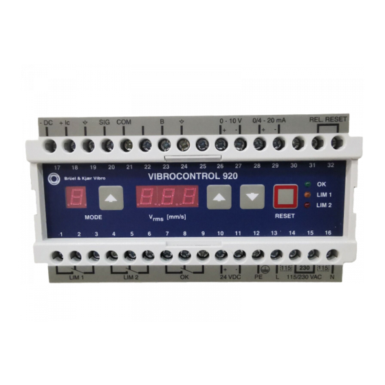
Page 10: Display And Operating Elements
VIBROCONTROL 920 Display and operating elements __________________________________________________________________________________ Display and operating elements Button: MODE The operating mode of the instrument is changed by pushing the MODE button. Normal operation One push of the button; Preparation for parameter entry resp. check mode. -
Page 11: Status Signals
Display and operating elements VIBROCONTROL 920 Status signals OK error The occurrence of an OK-error is indicated by the extinction of the LED. The OK relay is de-energized. LIM 1, LIM 2 error signals The behaviour of the limit relays is determined by the connection status of the terminals 31/32 (Relay Reset). -
Page 12: Reset
VIBROCONTROL 920 Display and operating elements __________________________________________________________________________________ Limit value LIM 2 Red LED / LIM 2 Relay If the current measurement value is higher than the limit value and remains at this level for longer than the set time delay, the LED will light up. The LIM 2 relay will react according to the defined setup. -
Page 13: Internal Tests And Error Signals
Display and operating elements VIBROCONTROL 920 Internal Tests and Error Signals After switching the instrument on a number of tests are executed. If the result of the test reveals an error in the operation of the instrument, this is displayed on the measurement value field in the form of an error message. - Page 14 VIBROCONTROL 920 Internal Tests and Error Signals __________________________________________________________________________________ Error " 01" The value of the calibration constants lies outside the permissible range. A value between 0.5 and 2.0 is permitted. Occurrence of this error means an error in the instrument’s internal acquisition electronics. The instrument should be removed from the monitoring application and returned to the nearest service station for repairs.
-
Page 15: Setups
Display and operating elements VIBROCONTROL 920 Setups General The parameters are divided into three Groups each with respectively seven parameters. The parameters in Groups 1 and 2 are concerned with configuration parameters while those in Group 3 are concerned with service parameters. -
Page 16: Function: Changing Parameter Values
VIBROCONTROL 920 Setups __________________________________________________________________________________ Function: Changing parameter values MODE button Push once. The number 1 is displayed in the mode display field. resp buttons Push repeatedly until the code number associated with the corresponding parameter Group is displayed. Parameter Group... -
Page 17: Parameter: Group 1
Display and operating elements VIBROCONTROL 920 Parameter: Group 1 Mode 1 Code number Value: 11 Mode 2 Range allocation for analog output Default value: 20 mm/s Value Equals 0 ... 10 mm/s 0 ... 20 mm/s 0 ... 50 mm/s 0 ... - Page 18 VIBROCONTROL 920 Setups __________________________________________________________________________________ Mode 4 Limit value LIM 2 Default value: 7 mm/s The adjustable range of the limit value is from 0 to the full scale value of the selected range. The resolution of the steps in the adjustment is in every case dependent on the selected range.
-
Page 19: Parameter: Group 2
Display and operating elements VIBROCONTROL 920 Parameter: Group 2 Mode 1 Code number Value: 22 Mode 2 Sensor sensitivity Default value: 100 mV/mm/s At the same time the sensitivity of an acceleration sensor is selected, the integration for conversion of vibration acceleration to vibration velocity is activated. - Page 20 VIBROCONTROL 920 Setups __________________________________________________________________________________ Mode 5 Limit relays operating mode Default value: 0 This parameter affects both limit relays. Selection Mode Normally energized Normally de-energized Normally energized: The relay de-energizes when the limit is exceeded Normally de-energized: The relay energizes when the limit is...
- Page 21 Display and operating elements VIBROCONTROL 920 Mode 7 Analog output and Display test Default value: 1 For test purposes various constant values, besides the standard signal, are switched to the analog outputs. To leave this test function activate RESET button.
-
Page 22: Parameter: Group 3 Service Parameter
VIBROCONTROL 920 Setups __________________________________________________________________________________ Parameter: Group 3 Service Parameter Mode 1 Code number Value: 3 Mode 2 DC rest voltage of the sensor The DC rest voltage of the sensor is displayed. This should be in case of sensors •... -
Page 23: Mounting And Installation
Mounting and Installation VIBROCONTROL 920 Mounting and Installation Mounting and Installation Instructions see the following page The quality of the masurements and the security of the electromagnetic resistance is dependent on a fault-free interference discharge and thus also on the cabling and disturbance-free grounding at the installation. - Page 24 Expose and shape the cable shield in the form of a ring at the height of the grounding rail only to the width of the grounding rail, so that the cable remains shielded right up to close to the VIBROCONTROL 920. The cable shield must be exposed only over the grounding rail.
-
Page 25: Mounting
• Dimensions 150 mm x 78 mm x 115 mm (W x H x D) Note! The assembly of the VIBROCONTROL 920 must not be undertaken in areas with permanent vibrations. Possibly a vibration-isolated installation must be implemented. VC920E / C102833.002 / V 13... - Page 26 VIBROCONTROL 920 Mounting and Installation This page is for your notes Page 24 / 33 VC920E / C102833.002 / V 13...
-
Page 27: Wiring Diagrams
Wiring diagrams VIBROCONTROL 920 Wiring diagrams VC - 920 SE-Schiene bus bar Rel. Reset 0 / 4 - 20 mA 0 - 10V VS-06x VS-077 AC-2104/0 VS-079 BN=0V WH=SIG PE>1,5mm PE>1,5mm - DC *Schirm an Kabelverschraubung Shield on cable screw... - Page 28 VIBROCONTROL 920 Wiring diagrams VC-920 SE-Schiene Grounding rail barre de blindage 115V Rel.Reset 230V 115V 0/4-20mA 0-10V +24V AC-2104/0 AS-02x WH=0V WH=COM LIM 2 YE=SIG YE=SIG AC-112 BK=0V LIM 1 RD=-24V RD=-24V PE>1,5mm PE>1,5mm *Schirm an Kabelverschraubung Shield on cable screw...
- Page 29 Wiring diagrams VIBROCONTROL 920 VC-920 SE-Schiene Grounding rail barre de blindage 445V Rel.Reset 230V 445V 0/4-20mA 0-10V / 54V AC-2104/0 AS-030 WH=COM LIM 2 YE=SIG AC-112 AC-112 BK=0V LIM 1 RD=-24V PE>1,5mm PE>1,5mm VC92AS30 (050405) *Schirm an Kabelverschraubung Shield on cable screw Blindage sur boulonnage Vibration accelerometer;...
- Page 30 VIBROCONTROL 920 Wiring diagrams SE-Schiene VC-920 bus bar 115V Rel.Reset 230V 115V 0/4-20mA PE 12 0V 11 0-10V +24V 10 AS-062 24 / AC-2104/0 AS-080 23 / 21 / LIM 2 SIG/I 18 / LIM 1 PE>1,5mm 17 / PE>1,5mm...
-
Page 31: Service
Service VIBROCONTROL 920 Service In accordance with general valid quality assurance measures the instrument should be subjected to testing, calibration and/or adjustment at regular intervals. This can be done either by the on-site service personnel, at the Brüel Kjær Vibro Ltd manufacturing facility or at one of the authorized Brüel Kjær Vibro service stations. -
Page 32: Instrument Versions
VIBROCONTROL 920 Instrument versions Instrument versions Version < 2.8 Filter settings The value for the lower filter frequency amounts to 3 Hz resp. 10 Hz Conduct at switch-on During the self-test after switch-on or return of power, the OK relay and limit relays will be in the de-energized condition. -
Page 33: Parameter List
Parameter list VIBROCONTROL 920 Parameter list Instrument number ................Measurement point ............................................... Parameter Group 1 Mode 2 Range assignment for analog output ............mm/s Mode 3 Limit value LIM 1 ............mm/s Mode 4 Limit value LIM 2 ............ - Page 34 VIBROCONTROL 920 Parameter list Page 32 / 33 VC920E / C102833.002 / V 13...
- Page 35 Parameter list VIBROCONTROL 920 VC920E / C102833.002 / V 13 Page 33 / 33...
Need help?
Do you have a question about the VIBROCONTROL 920 and is the answer not in the manual?
Questions and answers