
Related Manuals for BRUEL & KJAER VIBROPORT 80


Summary of Contents for BRUEL & KJAER VIBROPORT 80
- Page 1 VIBROPORT 80 VP-80 / VP-80 E Vibration analysis Rotor balancing Machine maintenance Brüel & Kjær Vibro GmbH - Leydhecker Str. 10 - 64293 Darmstadt Translation of the Original Operating Instructions VP-80 VP-80 E // 3G...
- Page 2 Company details Contact Brüel & Kjær Vibro GmbH Leydhecker Str. 10 64293 Darmstadt Service Hotline Tel.: +49(0)6151 / 428 1400 Fax: +49(0)6151 / 428 1401 E-Mail: info@bkvibro.com Internet: www.bkvibro.com Exclusion of liability We have compiled our technical documentation very carefully. All information has been provided in accordance with the state-of-the-art and to the best of our knowledge and belief.
- Page 3 Achtung ! Note! ATTENTION ! Vor Inbetriebnahme des Produktes Before operating the product the Avant utilisation de l'appareil, il faut muss die Betriebsanleitung gelesen manual must be read and impérativement avoir lu et compris und verstanden werden. understood. le manuel d'emploi. Bei Bedarf die Betriebsanleitung in If necessary you may order the Si besoin, commander le manuel...
- Page 4 Pozor! Uzman bu! D mesio! Pred zagonom proizvoda morate Pirms produkta ekspluat cijas Prieš pradedant naudoti produkt , najprej prebrati in razumeti navodilo uzs kšanas, r p gi izlasiet atidžiai perskaitykite instrukcij . za uporabo. lietošanas instrukciju. Esant reikalui, reikalaukite Po potrebi zahtevajte navodilo za Vajadz bas gad jum pieprasiet instrukcijos tr kstama ES kalba...
-
Page 5: Table Of Contents
ATEX certificate and markings ............1-10 General information ................1-11 Safety advice ..................1-12 Scope of Supply (Basic Unit) ............1-16 Technical Data.................1-18 Basic Operation................1-25 Overview of hardware for the VIBROPORT 80 ........1-25 6.1.1 Front .....................1-25 6.1.2 Connection plate ................1-30 6.1.3 Power supply module ..............1-35 6.1.4... - Page 6 Translation of the Original Operating Instructions VP-80/VP-80 E Operator Interface ................1-54 Explanation of symbols ..............1-54 Structure of the operator interface ...........1-55 Main mask ..................1-57 Licensing ..................1-58 Module overview ................1-59 Softkeys ...................1-65 7.6.1 General ..................1-65 7.6.2 Generally valid softkeys ...............1-66 7.6.3 Level 1 / Main mask ..............1-66 7.6.4 Level 2 / Modules .................1-69...
- Page 7 Translation of the Original Operating Instructions VP-80/VP-80 E Tracking ..................1-110 9.6.1 Tracking - signal processing setup ..........1-113 Transfer Function ................1-114 Time Signal ..................1-118 Recycling / Disposal ..............1-120 CE Declaration of Conformity ............1-121 Supplier´s Declaration of Conformity .........1-122...
-
Page 8: Basic Information
VP-80/VP-80 E Basic Information Technical specifications The VIBROPORT 80 / VIBROPORT 80 E is a portable and flexible vibration measuring and balancing instrument. The VIBROPORT 80 can be used for a multitude of measu- ring tasks and supports up to four input channels for vibration, to which all standard types of vibration sensors can be con- nected. -
Page 9: Intended Use
The relevant data are logged, displayed and stored. Obvious misuse The VIBROPORT 80 is not intended for use as a stationary monitoring unit for machines nor for providing alerts in respect of machine states. No relays / signal outputs are provided for this purpose, as with other products from Brüel &... -
Page 10: Explanation Of Symbols And Terminology
Translation of the Original Operating Instructions VP-80/VP-80 E Explanation of symbols and terminology Explanation of symbols Our products are manufactured according to state-of-the-art technology and in compliance with the acknowledged safety regulations. However, residual dangers do still exist, and refe- rence is made to these in the documentation in the form of pictograms. - Page 11 VIBROPORT 80. It also refers to critical situations which can result in damage to the VIBROPORT 80 or malfunctions and false measuring results. Instructions The following symbols are used to help you when carrying out actions: This is an action step / instruction directed at you.
-
Page 12: Safety Advice
When handling the VIBROPORT 80 and its accessories, the live components constitute a potential hazard source. Volta- ges of over 50 V do not occur in the VIBROPORT 80 but only in the power supply module, and are generally categorized as hazardous. - Page 13 VIBROPORT 80. Note! Only use genuine spare parts in the VIBROPORT 80. Note! The VIBROPORT 80 is not designed for long-term use under UV light. Note! Before commissioning, test the local mains voltage check and compare it with the voltage range of the AC-7001 power supply module.
-
Page 14: Handling Vibration Measuring And Monitoring Instruments
Use a slightly damp cloth for cleaning. Note! The seals of the battery compartment, the SD storage card slot and the housing of the VIBROPORT 80 must be regularly checked to ensure the integrity of the water and dust protec- tion. -
Page 15: Unauthorized Modifications
The EMC has been tested in accordance with EN 61326:2006, with reduction of the requirement for static elec- tricity (ESD) from 4kV to 2kV (EN 61000-4-2). The VIBROPORT 80 fulfils Class A (industrial sector) for emit- ted interference in accordance with EN55011. Note! Avoid electrostatic discharges in the area of sockets / con- nections (input channels). -
Page 16: Low Voltage Directive
Electromagnetic interference can influence the measured values and should be avoided as far as possible. Low Voltage Directive The VIBROPORT 80 fulfils the relevant requirements of Low Voltage Directive 2006 / 95 / EC in accordance with EN 61010:2010. IP protection... -
Page 17: Safety In Potentially Explosive Atmospheres
Translation of the Original Operating Instructions VP-80/VP-80 E Safety in Potentially Explosive Atmospheres ATEX certificate and markings Explosion protection according to 94/9/EC, only for VP-80 E. EC-type examination certificate TRAC10ATEX31265X Marking ATEX II 3G Ex ic IIC T4 Gc Ta= -10°C to +50°C Compliance with standards EN 60079-0:2009 EN 60079-11:2007... -
Page 18: General Information
CSA Class I, Div 2 Groups A, B, C & D, Temperature Code T4A@Ta=50C General information In the following you will find safety advice in relation to the use of the VIBROPORT 80 E in potentially explosive atmosphe- res. This information is based on Directive ATEX 94/9/EC. Note! -
Page 19: Safety Advice
WARNING! Explosive atmosphere! All unused connections (input sockets) must be covered with protective caps when using the VIBROPORT 80 E in a poten- tially explosive atmosphere. Connections without protective caps can cause explosions, resulting in damage to property and injuries. - Page 20 Tab. 2 Overview of sensors defined by ATEX / IECEx WARNING! Explosive atmosphere! Do not charge the battery of the VIBROPORT 80 E in potenti- ally explosive atmospheres. The power supply module and docking station must not be operated in Ex zones.
- Page 21 Translation of the Original Operating Instructions VP-80/VP-80 E WARNING! Explosive atmosphere! Do not change the battery and the power supply module of the device in potentially explosive atmospheres. This can cause explosions, resulting in damage to property and injuries. • Therefore only change the battery outside potentially explosive atmospheres.
- Page 22 Translation of the Original Operating Instructions VP-80/VP-80 E WARNING! Explosive atmosphere! The housing must be opened when performing a cold start (see “Performing a cold start” on page 46). This can cause explosions, resulting in damage to property and injuries. •...
-
Page 23: Scope Of Supply (Basic Unit)
Translation of the Original Operating Instructions VP-80/VP-80 E Scope of Supply (Basic Unit) VIBROPORT 80 – Analyzer Select comprising: • One VIBROPORT 80 measuring instrument with standard accessories • Delivered in AC-7101 shipping case • One Report & EXaminer software Standard/Client license and CMC USB driver on CD (with USB dongle) •... - Page 24 Balancing: Module 7 VIBROPORT 80 E Note! The hardware of the VIBROPORT 80 E only differs very slightly from that of the VP-80. In particular, the BP-15-CC (AC-7004) battery and the housing are designed for potenti- ally explosive atmospheres, as are the relevant sensors PA-...
-
Page 25: Technical Data
Translation of the Original Operating Instructions VP-80/VP-80 E Technical Data In the following we have provided an overview of the most im- portant technical data of the VIBROPORT 80, divided into ca- tegories. Note! You can download a detailed description of the technical data as a PDF document from our website www.bkvibro.com. - Page 26 Translation of the Original Operating Instructions VP-80/VP-80 E Signal detection / Averaging • • Peak (true peak) • Peak-peak (true peak-peak) • Calculated peak • Calculated peak-peak • CREST factor • Averaging: RMS, Time-synchronous, Peak Hold, Expo- nential Measuring tasks •...
- Page 27 4 x vibration channels (1/X, 2/Y, 3/Z and 4/R) + reference / speed, Triax support 1/X, 2/Y, 3/Z @CH1 • In potentially explosive atmospheres only VIBROPORT 80 E with maximum 3 x vibration channels 1/X, 2/Y, 3/Z (Triax) + reference / speed •...
- Page 28 Translation of the Original Operating Instructions VP-80/VP-80 E Measuring range • Input channels: Nominal maximum ±25 volt peak-peak (overvoltage protection ± 50 V, transient) • Input amplification: Sensor unit, Autorange or maximum • Dynamic range: >90 dB • Frequency range: DC voltages, AC = 0.18 Hz to 80 kHz (max.
- Page 29 Translation of the Original Operating Instructions VP-80/VP-80 E Measuring accuracies • Overalls (AC, broad-band): 5% amplitude accuracy • Vector amplitude (AC, narrow-band): 5% amplitude accu- racy • Phase: +-3 degrees for the first three peaks and then +-6 degrees for all following peaks @60Hz •...
- Page 30 • Note operating temperature of AC-7001 power supply module • Shaking/vibration: according to MIL STD-810 Approvals/certificates • VIBROPORT 80 / VIBROPORT 80 E: CE • Power supply: CE • Docking station: CE • C-Tick registration number see name plate on VIBROPORT 80 •...
- Page 31 Translation of the Original Operating Instructions VP-80/VP-80 E Communication • USB (direct connection via connection socket of USB device/TRIG/PWR or via docking station) • Microsoft Windows ® XP: ActiveSync, Windows 7: Mobile Device Center • Operating system: Microsoft Windows ® Embedded CE •...
-
Page 32: Basic Operation
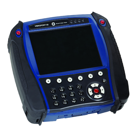
Translation of the Original Operating Instructions VP-80/VP-80 E Basic Operation Overview of hardware for the VIBROPORT 80 6.1.1 Front In the following you will find a detailed overview of the opera- ting controls for the VIBROPORT 80. Fig. 1 Front of the VP-80... - Page 33 The three red input keys (fire keys) are used to select modu- les, confirm inputs and sometimes to start measurements. Indicator lights (4x LED) The VIBROPORT 80 has four indicator lights (LEDs) in the colors blue, red, orange and green. These indicate the status as shown in the following LED table.
- Page 34 You can navigate, make settings and perform measuring tasks in the display. The measuring results are displayed here in the form of numeric or graphic displays. The status of the VIBROPORT 80 is also indicated here by means of symbols. Picto-...
- Page 35 [3] Function key 5 / INFO [2] Function key 2 / SYSTEM SETUP On/Off key The VIBROPORT 80 is switched on and off with the On/Off key. Press this key for approx. 2 to 3 seconds to switch the VIBROPORT 80 off. Note!
- Page 36 Translation of the Original Operating Instructions VP-80/VP-80 E Cursor keys Pictogram Description The cursor keys enable you to navigate through the menus and settings and to select functions / measuring modules. Navigating in the menus Navigate to the desired item in the menus with the (right), ...
-
Page 37: Connection Plate
Otherwise letters will be entered. 6.1.2 Connection plate The connection plate of the VIBROPORT 80 contains four connections (sockets) for connecting sensors, power supply modules and USB devices. Note! In addition to the cables and sensors available from Brüel &... - Page 38 Translation of the Original Operating Instructions VP-80/VP-80 E Fig. 3 Connection plate [1] Channel CH 1 [3] Channel USB HOST / CH R / Earphones [2] Channel CH 2 [4] Channel USB device / TRIG / PWR Connec- Standard sen- Pin assignment tion sors...
- Page 39 AC-7501 + AC- phones 1387 or alterna- tively AS-063 + Measuring channel 4/R: AC-1386 (CCS supply, AC/DC input), (with VIBROPORT 80 E do not use in potentially explosive atmospheres / Zone 2) (1) EXT-DC-IN, (2) Channel USB-Host Digital+, USB DEV /...
- Page 40 Translation of the Original Operating Instructions VP-80/VP-80 E Earphones The FFT-Analyzer and Balancer modules support the output of an audio signal and allow you to use earphones as a diag- nostic tool. Note! A multitude of further sensors can be connected with corres- ponding adapters from Brüel &...
- Page 41 Translation of the Original Operating Instructions VP-80/VP-80 E Vibration Chan- Chan- Chan- Channel measure- USB DEV/ ments TRIG/PWR Single- Measu- channel ring measure- (Speed) chan- ment nel 1 Measu- Measu- Two-chan- ring ring nel measu- (Speed) chan- chan- rement nel 1 nel 2 Three- Measu-...
-
Page 42: Power Supply Module
Use the power supply module to charge the battery. Do not cover the power supply module. Note! Before using the VIBROPORT 80 for the first time, the fitted battery must be charged for at least 24 hours, so that it can reach its full capacity. - Page 43 Translation of the Original Operating Instructions VP-80/VP-80 E Fig. 4 Power supply module Press the locking device down. Push the adapter forward. Replace the adapter and push the new adapter into the ad- apter guide of the power supply module until the adapter engages.
-
Page 44: Battery
Only the rechargeable battery / storage battery BP-15 (AC- 7003) may be fitted and used in the VIBROPORT 80. Only the rechargeable battery / storage battery BP-15-CC (AC-7004) may be fitted and used in the VIBROPORT 80 E. Note! The battery connections must not be short-circuited! This will cause damage to the battery / the VIBROPORT 80. - Page 45 Never use the docking station and power supply module in potentially explosive atmospheres. Note! Make sure that the VIBROPORT 80 is correctly positioned in the docking station charging cradle, as otherwise the battery will not be charged correctly. Note the indicator light display (LEDs)! Fig.
- Page 46 6.1.4.2 Charging the battery via the power supply module WARNING! Explosive atmosphere! Do not charge the battery of the VIBROPORT 80 E in potenti- ally explosive atmospheres. The power supply module and docking station must not be operated in Ex zones.
- Page 47 Translation of the Original Operating Instructions VP-80/VP-80 E 6.1.4.3 Changing the battery WARNING! Explosive atmosphere! Do not change the battery and the power supply module of the device in potentially explosive atmospheres. This can cause explosions, resulting in damage to property and injuries.
-
Page 48: Docking Station
Docking station Additional connections for the power supply and for USB de- vices can be found on the back of the docking station of the VIBROPORT 80. Fig. 6 Docking station [1] Connection of external [3] USB connection for con-... -
Page 49: Folding Out The Bracket
Here you can connect the VIBROPORT 80 in the docking sta- tion to a PC via USB connection. Data can then be exchanged between the VIBROPORT 80 and the PC and / or further pro- cessed and analyzed on the PC using the Report & EXaminer software. -
Page 50: Sd Storage Card Slot
6.1.7 SD storage card slot Note! In addition to the internal memory, the VIBROPORT 80 has a storage card slot for inserting an SD storage card with up to 16 GB storage capacity. The recommended supplier is San- Disk (the “Secure Digital Card SDSDx-yyy” type is the only one that can be used for the EX zone!). -
Page 51: Inserting The Sd Storage Card
• Only insert and replace the SD storage card in non-hazar- dous atmospheres. Insert the storage card for the VIBROPORT 80 as follows: Loosen the two holding screws of the card slot by giving a quarter turn clockwise (90°) (see following illustration). -
Page 52: Connecting The Vibroport 80 To The Pc
You have inserted the SD storage card. Connecting the VIBROPORT 80 to the PC 6.2.1 Connecting via the USB interface Connect the VIBROPORT 80 to a PC as follows: Directly via the USB connection: Insert the Y-cable (AC-1389) into the USB DEV / TRIG / ... -
Page 53: Synchronization Software
6.2.2 Synchronization software Note! When the VIBROPORT 80 is connected to the PC, no data from the operating system, firmware or other important data may be deleted. This would cancel out the functionality of the VP-80 and result in voiding of the warranty. -
Page 54: Report & Examiner Software
Reports can be generated quickly and easily with the Report & EXaminer software from measurements stored in the measuring instrument. The VIBROPORT 80 is connected to the PC by means of a USB interface. The optional premium version enables you to analyze previ- ously stored time signal data sets (.wav files) so they can be... - Page 55 In conjunction with the Report & EXaminer software module names and analysis software, the VIBROPORT 80 has vari- ous special features in the implemented directory structure. As the VIBROPORT 80 platform is a Windows system, you can access the directories of the VIBROPORT 80 directly. Note! Retain the existing directory structure.
- Page 56 Report & EXaminer software and for data analy- sis. The following table provides an overview of the assignment of measuring files from the modules to the directory structure on the VIBROPORT 80: Overalls, FFT Analysis, Balancing, Tracking and Transfer Function modules Directory path and...
- Page 57 The Time Signal and Acceptance Test modules save some measuring data in the FFT Analysis module. It is thus possib- le, for example, to view recorded spectra from a performed acceptance test directly on the VIBROPORT 80. Directory path and Explanation and...
- Page 58 Translation of the Original Operating Instructions VP-80/VP-80 E Directory path and Explanation and Module directory name on file format VP-80 Results are stored \Internal Disk\Conf- as *.CCR. Optional – Check\Saved depending on the *.CCS test template \Storage Card\Conf- – the results are also Check\Saved stored as *.csv.
-
Page 59: Reset Function
Press and hold down the function keys 2, 7, 8, 9 simultane- ously for two to three seconds. The VIBROPORT 80 restarts. 6.3.2 Performing a cold start A cold start of the VP-80 resets the device to delivery status. - Page 60 Remove the battery pack from the compartment. The bat- tery can remain connected to the device. Press the reset key using a pointed object. The VIBROPORT 80 restarts. Put the battery back in the battery compartment. Secure the battery with the Velcro straps. ...
-
Page 61: Operator Interface
Translation of the Original Operating Instructions VP-80/VP-80 E Operator Interface This chapter provides a detailed overview of using the opera- tor interface of the VIBROPORT 80 and the basic operating concept. The general mode of functioning implemented by the firmware is also described. -
Page 62: Structure Of The Operator Interface
Translation of the Original Operating Instructions VP-80/VP-80 E Structure of the operator interface The screen of the VIBROPORT 80 is dynamically divided in up to four areas. These offer different functions, which will now be described in more detail. Fig. 10 Structure of the operator interface... - Page 63 The name of the current mask is shown on the left of the info line. • If the VIBROPORT 80 has an SD storage card, this is indi- cated by a diskette symbol. • The state of the fitted battery or the connection to the power supply module is displayed on the right.
-
Page 64: Main Mask
Translation of the Original Operating Instructions VP-80/VP-80 E Main mask The main mask appears when the VIBROPORT 80 is swit- ched on. You can access all of your modules from here. Fig. 11 Main mask Note! Only some of the displayed modules can be installed, depen- ding on the licensed features of your VP-80. -
Page 65: Licensing
You can use the softkeys HELP, SYSTEM SETUP (the general system setup) and INFO at the bottom of the screen to call up basic information on the VIBROPORT 80. Licensing You can retrospectively purchase and install modules on your VP-80. Modules which are not yet installed have a gray back- ground. -
Page 66: Module Overview
Translation of the Original Operating Instructions VP-80/VP-80 E Module overview Picto- Description of the module gram Overalls The Overalls Module allows you to analyze the overall condition of a machine and com- pare it to the limit values according to DIN ISO 10816 or the manufacturer’s data and empirical values, for example. - Page 67 Translation of the Original Operating Instructions VP-80/VP-80 E Picto- Description of the module gram FFT-Analyzer The FFT-Analyzer Module allows you to break down an overall vibration (mixture of vibrations) into its individual harmonic compo- nents. Different spectral lines are determined with their own specific frequency and ampli- tude.
- Page 68 Translation of the Original Operating Instructions VP-80/VP-80 E Picto- Description of the module gram Balancer The majority of vibration problems on machi- nes can be traced back to rotor imbalances. The Balancer Module allows you to balance installed rotors (field balancing). This means no disassembly or transport of the rotor, con- sideration of the installation situation and balancing irrespective of the size and weight...
- Page 69 Translation of the Original Operating Instructions VP-80/VP-80 E Picto- Description of the module gram Tracking Tracking is carried out during operation of the machine and serves to analyze the rotor fre- quency-induced vibration components and their harmonics with speed variation. The Tra- cking measuring module can be utilized for both run-up and coast-down of the machine.
- Page 70 Translation of the Original Operating Instructions VP-80/VP-80 E Picto- Description of the module gram Transfer Function The Transfer Function Module enables you to carry out structural tests on machines with shafts that are not rotating and to analyze immovable objects such as, e.g. foundations or frameworks.
- Page 71 System Setup In the System Setup you can define the most important global system parameters of the VIBROPORT 80, such as the system of units or the time, for example. Sensor Setup In the Sensor Setup you can look at the set- tings for the sensors predefined in the measu- ring modules (Brüel &...
-
Page 72: Softkeys
I.e. the functionality of the softkeys is context-sensitive. For example: SYSTEM SETUP or START. Note! The operator interface of the VIBROPORT 80 has four levels in which you can navigate with the softkeys (see following figure). -
Page 73: Generally Valid Softkeys
Translation of the Original Operating Instructions VP-80/VP-80 E Level 1 Main mask Level 2 Measuring Modules mask Level 3 Report mask Setup mask Level 4 Measurements mask Fig. 12 Levels of the operator interface 7.6.2 Generally valid softkeys This chapter provides an overview of the functions of the soft- keys that are valid for all modules. - Page 74 Translation of the Original Operating Instructions VP-80/VP-80 E HELP The online help is called up with this softkey. Here you can obtain information on: • Program Manager • Information on the operator interface, basic operation (cursor keys, fire keys) and a brief description of the various modules are displayed here.
- Page 75 The System Setup is described in detail in a separate chapter. INFO When the INFO softkey is executed, additional information on the VIBROPORT 80 and the installed modules / software ver- sion and the available memory is displayed. • Software version •...
-
Page 76: Level 2 / Modules
Translation of the Original Operating Instructions VP-80/VP-80 E > INFO Pressing the displayed INFO softkey again using function key F2 gives you access to further information on the VIBRO- PORT 80. However, this is not relevant for standard use. 7.6.4 Level 2 / Modules Note! The softkeys on the second level, i.e. - Page 77 Translation of the Original Operating Instructions VP-80/VP-80 E SETUP Select a predefined measurement, the last measurement or a new measurement with the cursor keys. You can use the SETUP softkey or the fire key to call up the respective setup for the selected mask or measuring task and to adjust the setup parameters (for example hardware used, units, high-pass/low-pass, limit frequency, etc.).
-
Page 78: Level 3 / Measurement Setup And Report Mask
Translation of the Original Operating Instructions VP-80/VP-80 E 7.6.5 Level 3 / Measurement setup and report mask Measurements that are started with the fire key open a setup input mask before the measurement, where the settings for the measurement are defined. Note! All softkeys are only available here, if a measuring file or setup file has been selected in the report mask! - Page 79 BACKUP The file selected with the cursor keys is saved by executing this softkey on the SD storage card of the VIBROPORT 80. DELETE The file selected with the cursor keys (saved setup/measure- ment) is deleted after a security query by executing this soft- key.
-
Page 80: Level 4 / Measurements Mask
Translation of the Original Operating Instructions VP-80/VP-80 E 7.6.6 Level 4 / Measurements mask This is the level in which the actual measurements are perfor- med. Although this can be accessed directly from the second level (START softkey on a blue icon), it is normally only ac- cessed from the third level (setup). - Page 81 Translation of the Original Operating Instructions VP-80/VP-80 E LOG / LINEAR When the LOG softkey is activated the Y-axis is scaled loga- rithmically and the LINEAR softkey is displayed. The LINEAR softkey scales the Y-axis linearly. CPM / HZ This softkey switches the display between the units rpm (revo- lutions per minute) and HZ (vibrations per second).
- Page 82 Translation of the Original Operating Instructions VP-80/VP-80 E POLAR / BARGRAPH When the POLAR softkey is activated balancing is displayed in a polar view, and when the BARGRAPH softkey is activa- ted the vibration values are shown as a bar chart. TABLE The TABLE softkey opens the Summary mask, which dis- plays the measuring values as a table.
-
Page 83: Measuring Data Analysis - Zoom And Cursor Keys
Translation of the Original Operating Instructions VP-80/VP-80 E Measuring data analysis - zoom and cursor keys You can select individual measuring data values in measure- ments with the cursor keys and magnify measuring curves with the zoom key. This allows you to view measuring ranges in more detail and analyze them. - Page 84 Translation of the Original Operating Instructions VP-80/VP-80 E Using the cursor keys During the measurement and when it is finished, information about individual spectral lines/amplitudes can be selected with a cursor. Note! The current X/Y position of the cursor is displayed in the top left corner (near the header line).
-
Page 85: Setup Settings
Select the System Setup menu item with the cursor keys. Press the fire key or the SYSTEM SETUP function key. Fig. 13 System Setup Softkeys DARKER / BRIGHTER These softkeys incrementally reduce / increase the screen brightness of the VIBROPORT 80. - Page 86 PORT 80. Special attention should be paid to deinstalling. Deinstalling should only be carried out if you are certain that a module is no longer required. Deinstalling modules will relieve the processor of the VIBROPORT 80 and thus incre- ase processing speed. •...
- Page 87 (Off). Units Here you can define the system of units used by the VIBROPORT 80. You can select the metric system of units (Metric) or the Anglo-saxon system of units (Imperial). Channel setup The channel setup defines the input channels for the measu- rement.
- Page 88 Translation of the Original Operating Instructions VP-80/VP-80 E Speed measurement The speed measurement parameter defines how the rotatio- nal speed will be displayed. You can select revolutions per mi- nute (rpm) or number of vibrations per second (Hz), or the setting can be deactivated (Inactive).
- Page 89 Translation of the Original Operating Instructions VP-80/VP-80 E Visual trigger The visual trigger type allows you to visually display the current trigger level and trigger signal. This makes it easier to determine and set a sensible trigger threshold. The trigger level is selected with the (up) cursor key. This functionality is also available in the Balancer module.
-
Page 90: Sensor Setup
Translation of the Original Operating Instructions VP-80/VP-80 E Time zone Define the time zone used by the device here. All time zones are stored here - simply select the right one. Date/Time Here you can set the date and time according to the date for- mat for each input field. - Page 91 Translation of the Original Operating Instructions VP-80/VP-80 E Go to the Main Mask. Select Sensor Setup with the cursor keys. Press the fire key or the SETUP function key. Fig. 14 Sensor Setup All previously acquired sensors are displayed here. The NEW softkey adds an additional sensor.
- Page 92 VP-80/VP-80 E DELETE The DELETE softkey permanently deletes the selected sen- sor from the memory of the VIBROPORT 80. A security query must be confirmed before deletion. Note! When deleting a sensor please note that it will no longer be available for measurements, or will have to be newly created first of all.
-
Page 93: Example Measurement - Overalls
Translation of the Original Operating Instructions VP-80/VP-80 E Example measurement - Overalls The Overalls module allows you to analyze the overall condi- tion of a machine and compare it to the limit values establis- hed by DIN ISO 10816 or the manufacturer’s data and empirical values, for example. - Page 94 Translation of the Original Operating Instructions VP-80/VP-80 E Fig. 15 Overview of overalls [1] Last measurement [3] New measurement [2] Predefined measurement [4] Report Note! There are several options for performing a measurement. Last measurement Last measurement saves the setup last used for a measure- ment.
- Page 95 Translation of the Original Operating Instructions VP-80/VP-80 E Predefined measurements Here you can start the measurements (measuring tasks) pre- defined by Brüel & Kjær Vibro GmbH. The predefined measu- rements reflect frequently occurring, typical and important measuring tasks in condition monitoring. The settings for the respective measurement are already predefined and cannot be deleted by the user.
-
Page 96: Start Of Example Measurement
The procedures and settings described below can therefore be transferred to the other modules. Proceed as follows: Start the VIBROPORT 80 with the On/Off key. The device starts. The main mask appears. -
Page 97: Perform Predefined Measurement
Translation of the Original Operating Instructions VP-80/VP-80 E Perform predefined measurement Predefined measurements are specifically designed for fre- quently occurring measuring tasks. Therefore these measu- ring tasks do not have to be specially created and saved. Predefined measuring tasks can be started directly (START softkey) or configured (fire key) or SETUP softkey before star- ting the measurement. -
Page 98: Perform Last Measurement And Check Setup
Translation of the Original Operating Instructions VP-80/VP-80 E Perform last measurement and check setup If you wish to call up and check the settings of the Last mea- surement (or a predefined measurement) before you perform this measurement, proceed as follows: Press the fire key (or the SETUP softkey). -
Page 99: Directly Start Last Measurement
Translation of the Original Operating Instructions VP-80/VP-80 E Directly start last measurement If you wish to repeat the Last measurement carried out, pro- ceed as follows: Press the START softkey. The Overalls data mask opens and the measurement starts directly (indicated by softkey F5 which displays STOP = Measurement running). -
Page 100: Change Display / Representation During Measurement
Translation of the Original Operating Instructions VP-80/VP-80 E During execution of the measurement you can: • Call up an average determination to stabilize the measu- ring values (AVERAGE). • Change the representation (VIEW). • Record the data over speed f(n) or time f(t) (RECORD), if you have previously defined this in the setup. -
Page 101: End Current Measurement
Translation of the Original Operating Instructions VP-80/VP-80 E You can select individual representations (tabular view) or combine different representations (tabular view + bar graph). Start the measurement with the START softkey. Press the VIEW softkey. The following mask opens: ... -
Page 102: Save Measurement
Translation of the Original Operating Instructions VP-80/VP-80 E STORE When you press this softkey the current measurement is sa- ved as a report and can be called up again later. EXIT The measurement is rejected, not saved and you are returned to the Overalls mask. - Page 103 Translation of the Original Operating Instructions VP-80/VP-80 E Fig. 20 Report overview Allocate a new name for the measurement, using the al- phanumeric keypad or accept the name suggested by the VP-80 (Name: Date / Time). Press the OK softkey. ...
-
Page 104: Load And Execute Saved Measurement (Open Report)
Translation of the Original Operating Instructions VP-80/VP-80 E Load and execute saved measurement (open report) Either load saved measurements, so that you can reuse their setup for another measuring task, or directly use one of the setups stored here for your next measurement. The REPORT mask will assist you. -
Page 105: Setup Parameters For The Measuring Modules
Translation of the Original Operating Instructions VP-80/VP-80 E Setup Parameters for the Measuring Modules General The following tables will help you to understand and set the options and setup parameters for the individual modules. A setting option and an explanation are provided for each pa- rameter. -
Page 106: Fft-Analyzer Module
Translation of the Original Operating Instructions VP-80/VP-80 E The following table indicates the order of magnitude of the noise values depending on the high-pass filter frequency (HPF). The designations in the top row refer to single or doub- le integration including signal detection. mm/s mm/s p mm/s μm... -
Page 107: Time Signal Module
Translation of the Original Operating Instructions VP-80/VP-80 E 9.2.4 Time Signal module Display The Time Signal module is based on a special procedure du- ring measurement. In a first step, a live preview of the existing time signal including offset is displayed. When you have star- ted the measurement the signal display is “frozen”, but the ac- tual measurement continues in the background until you end the measurement. -
Page 108: Overalls
Translation of the Original Operating Instructions VP-80/VP-80 E Overalls Setting para- Explanation of the Parameter meter parameter Input chan- CH1(&CH2&CH Definition of the num- nels 3&CH4) ber of input channels. B&K Vibro sen- Sensor sors; Process; Sensor type Variable B&K Vibro sen- Selection in sors e.g. - Page 109 Translation of the Original Operating Instructions VP-80/VP-80 E Setting para- Explanation of the Parameter meter parameter Depending on the set- ting in the System Automatic Sca- Setup, only appears if Input range ling; Maximum; Sensor Units has been Sensor Units selected.
- Page 110 Translation of the Original Operating Instructions VP-80/VP-80 E Setting para- Explanation of the Parameter meter parameter High-pass limit fre- quency for path B High-pass [B] e.g. 10 Hz (range depends on input channel setting). Low-pass limit fre- quency for path B Low-pass [B] e.g.
-
Page 111: Fft-Analyzer
Translation of the Original Operating Instructions VP-80/VP-80 E FFT-Analyzer Setting para- Explanation of para- Parameter meter meter Input Chan- CH1(&CH2&CH Definition of the num- nels 3&CH4) ber of input channels. B&K Vibro sen- Sensor Sensor type sors; Variable Sensor Units e.g. - Page 112 Translation of the Original Operating Instructions VP-80/VP-80 E Setting para- Explanation of para- Parameter meter meter High-pass limit fre- quency (range High-Pass e.g. 10 Hz depends on input channel setting). Low-pass limit fre- quency (range Low-Pass e.g. 1000 Hz depends on input channel setting).
- Page 113 Translation of the Original Operating Instructions VP-80/VP-80 E Setting para- Explanation of para- Parameter meter meter rms; Exponen- Type of averaging tial; PeakHold; (depends on speed Avg. Type Time-synchro- activation in System nous Setup). Num. Aver- 1 to 255 Number of averages. ages Overlap when editing or calculating the FFT.
-
Page 114: Balancer
Translation of the Original Operating Instructions VP-80/VP-80 E Balancer Setting para- Explanation of para- Parameter meter meter Single plane Selection of planes for (A=CH1); Two balancing. Two-plane plane (A=CH1 & Plane Setup balancing can also be B=CH2); Two performed sequenti- plane ally with a sensor. - Page 115 A is calculated after the initial run and trial run A. The residual vib- ration of plane 1 and plane 2 is predicted by the VIBROPORT 80. If the predicted residual vibration is adequate, trial run B can be omitted.
- Page 116 With component correction 3 - 99 fixed locations can be selected (e.g. fan vanes, equidistant holes on rotor circumference). The test weights are mounted in a fixed location for the trial run. VIBROPORT 80 calculates the correction weights for two (adjacent) component locations. Fixed weight correction With fixed weight correction the weight is preselected.
-
Page 117: Tracking
Translation of the Original Operating Instructions VP-80/VP-80 E Tracking Setting para- Explanation of para- Parameter meter meter Input Chan- Definition of the num- nels (&CH2&CH3) ber of input channels. B&K Vibro sen- Sensor Sensor type sors; Variable Sensor Units e.g. g Sensor unit e.g. - Page 118 Translation of the Original Operating Instructions VP-80/VP-80 E Setting para- Explanation of para- Parameter meter meter You can select whe- ther the system has a runup or a coastdown. Coastdown; Manual records data Record Mode Runup; Manual independently of speed, and can be used if no speed signal is available.
- Page 119 Translation of the Original Operating Instructions VP-80/VP-80 E Setting para- Explanation of para- Parameter meter meter Defines the maximum permissible time for data acquisition in seconds. Is adapted depending on the sto- Max. Acq rage medium selec- Time (s) ted, so that the maximum possible recording time is dis- played.
-
Page 120: Tracking - Signal Processing Setup
Translation of the Original Operating Instructions VP-80/VP-80 E 9.6.1 Tracking - signal processing setup Setting para- Explanation of para- Parameter meter meter Channel used for cal- Channels CH1; CH2; CH3 culation. Start Definition of data e.g. 600 rpm Speed(RPM) acquisition speed… Stop Definition of data e.g. -
Page 121: Transfer Function
Translation of the Original Operating Instructions VP-80/VP-80 E Transfer Function Setting para- Explanation of para- Parameter meter meter Input Chan- Definition of the num- (&CH2&CH3) ber of input channels. Hammer is set for measuring the trans- fer function. Conti- Excitation Hammer;... - Page 122 Translation of the Original Operating Instructions VP-80/VP-80 E Setting para- Explanation of para- Parameter meter meter Sensitivity per hammer H. Sens. e.g. 2 unit (mV/Hammer Unit). Constant Current Sup- H. CCS Power On; Off ply for impact hammer. Defines the type of transfer function and the display type.
- Page 123 Translation of the Original Operating Instructions VP-80/VP-80 E Setting para- Explanation of para- Parameter meter meter Frequency range of the determined trans- fer function. The recor- Low Pass 1 to 20,000 Hz ding time changes accordingly in the sta- tus window. Automatic;...
- Page 124 Translation of the Original Operating Instructions VP-80/VP-80 E Setting para- Explanation of para- Parameter meter meter Setting of the threshold value at which the transfer function is displayed red (poor coherence) or green (good cohe- Good Cohe- rence) according to the 1 % to 100 % rence percentage value.
-
Page 125: Time Signal
Translation of the Original Operating Instructions VP-80/VP-80 E Time Signal Setting para- Explanation of para- Parameter meter meter CH1 to CH4 or Definition of the num- Input Chan- CH1 to CH3 ber of input channels nels with speed sen- including / excluding sor. - Page 126 Translation of the Original Operating Instructions VP-80/VP-80 E Setting para- Explanation of para- Parameter meter meter Defines whether data recording will be trig- gered manually or by a Manual; CH1 trigger threshold value. Rec. Mode Level ; Tacho This trigger can be provided by the speed signal (Tacho) or a CH1 level.
-
Page 127: Recycling / Disposal
Translation of the Original Operating Instructions VP-80/VP-80 E Recycling / Disposal The defective / unusable AC-7003 battery must be correctly disposed of. There are special collection points for batteries. Batteries must not be disposed of as domestic waste, but as special waste! Observe the local regulations. -
Page 128: Ce Declaration Of Conformity
Translation of the Original Operating Instructions VP-80/VP-80 E CE Declaration of Conformity Fig. 22 CE Declaration of Conformity We guarantee that the accessories and products included in the scope of supply of the VP-80 have been tested by means of all necessary tests and fulfil all CE and EMC requirements. -
Page 129: Supplier´s Declaration Of Conformity
Translation of the Original Operating Instructions VP-80/VP-80 E Supplier´s Declaration of Conformity... - Page 130 Translation of the Original Operating Instructions VP-80/VP-80 E...
- Page 131 Brüel & Kjaer Vibro GmbH Leydhecker Str. 10 64293 Darmstadt Phone: +49 (0) 6151 428 11 00 Fax: +49 (0) 6151 428 12 00 E-Mail: info@bkvibro.com © Brüel & Kjaer Vibro GmbH...
Need help?
Do you have a question about the VIBROPORT 80 and is the answer not in the manual?
Questions and answers