Table of Contents
Advertisement
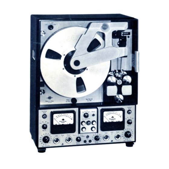
Tape Recorder Type 7001
The Tape
Recorder
channel precision laboratory recorder with particular
emphasis on frequency transformation .
frequency modulation
quency response is
are available with frequency transformation ratios of
4, 10
40. A
and
for tape identification and data reclaim. To allow for
sequential analysis of nonstationary signals a variable
length loop adaptor is supplied with the instrument.
The
instrument
design with plug-in card construction. Both recording
and reproduce heads are of the long life .!errite type.
The control panel is removable for remote
N�RUM, DENMARK. Teleph.: 80
has
been
designed
It uti I izes the
(FM)
techniques and the fre
DC
20,000
to
Hz. Four tape speeds
direct
recording channel
itself
is
of
a
compact
a
e x
0500.
C
b l e: BRUKJA. Te l
as
a
two
is included
operation.
: 5316. COPENHAGEN
F. ReI ...
..... ,.req1l1en4rJY 010111
Complex Modulu
A�
Condenser Mlcroph0ne8
Deviation Brldg
Distortion Measuring Brldg ..
FM-Tape Recorders
Frequency Analyzers
Frequency Measuring Brldgee
Hearl", Aid Teat Apparatus
Voltmeters
Hate
Level
ecorders
Megohmmeters
Microphone Acceaaorl ..
Microphone Amptlflers
Microphone Calibration Apparatu
Mobile Laboratories
01 .. Generators
No ... Limit Indicators
Plltonphones
Polar Diagram Reoorif ... .
Preamplifiers
Precl Ion Sound Level Meters
Recording Paper
Strain Gage Appa
Acceaaorles
Advertisement
Table of Contents

Subscribe to Our Youtube Channel
Related Manuals for BRUEL & KJAER 7001


Summary of Contents for BRUEL & KJAER 7001
- Page 1 Tape Recorder Type 7001 F. ReI ..,.req1l1en4rJY 010111 Complex Modulu A� Condenser Mlcroph0ne8 Deviation Brldg Distortion Measuring Brldg .. FM-Tape Recorders Frequency Analyzers Frequency Measuring Brldgee Hearl", Aid Teat Apparatus Voltmeters Hate Level ecorders Megohmmeters Microphone Acceaaorl ..
- Page 2 Verso Filler Page ♦ ♦...
- Page 3 Tape Recorder Type 7001 1967 NOVEMBER...
- Page 4 Verso Filler Page ♦ ♦...
-
Page 5: Table Of Contents
Contents Page Introduction ..........General Introduction The Principles of Magnetic Tape Recording Description... - Page 6 Verso Filler Page ♦ ♦ — 2 —...
-
Page 7: Introduction
D u e to t h i s s up e ri o rity of FM reco rd i n g i n a n a l o g meas u re m e n t syste ms t h e Tap e Rec o rd e r Typ e 7001 u t i l izes t h e F M tech n i q u e a n d g reat c a re h as been taken in t h e d eve l o p m e n t of t h e Reco rd e r to ac h i eve op t i m u m p e rfo rmance a n d re l i ab i l i ty of its va r i o u s c o mp o n e n ts. - Page 8 , see F i g . 1 . 1 . I n the Tap e Reco rd e r Typ e 7001 th e h i g h est carri e r f req u e n cy u sed i s 1 08 k H z a n d co nseq u e nt l y t h e h i g h est i n p u t s i g n a l f req u e n cy c o m p o n ent t h at c a n b e reco rd e d w i t h f u l l dynam i c ra n g e i s a p p rox i m ately 20 k H z .
- Page 9 l i nearity i n t h e c i rc u i t ry w h i l e t h e lowe r l i m it i s n o rm a l ly d eterm i ned by t h e w o w a n d f l utte r of t h e tape transpo rt a s wel l as s p u r i o u s ( ra n d o m) no i ses i n h e rent in the reco rd e r.
- Page 10 T h e c u rve shown h as been m easu red o n a p rototyp e Tape Reco rd e r Type 7001 w i th a tape s p eed of 3.81 c m/sec ( 1.5 i ps) . S i m i l a r c u rves fo r oth e r tape speeds are given i n F i g .
-
Page 11: Description
General T h e Tape Reco rd e r Typ e 7001 i s d e s i g ned bas i c a l l y as a two-cha n n e l l abo rato ry rec o rd e r fo r f req u e n cy transfo rmat i o n p u rposes. T h e reco rd i ng p r i n c i p l e s... - Page 12 Tape Rec o r d e r Type 7001 . F i n a l ly, F i g . 2 . 4 shows typ i cal i nhe rent no ise a n d f l utte r c u rves m easu red as a fu n c t i o n of the re p ro d u c e b a n d w i dth.
- Page 13 f If. - 1 0 Upper limiting frequency ¢ Phase difference - 2 5 /67209 in ·degrees Fig . 2.3. Limit lines for phase differenc es b e tween th e two m easurem ent channels contained in o ne Tape Recorder. that the d y n a m i c rang e fo r o n e thi rd octave f req u e n cy a n a l ys i s w i l l be show n i n F i g .
- Page 14 i.,:!!! lie_ ODOOODDDOOD o o aOODD o aO OODOaaO Q OOO O DO oaODDD O O DDOOD " 1'." 0 _,,_ _,,_ • :' " , , , 700 L ""t Anabsis Tope Sp.ed 6 ips ::'j81�_C Rl1S �� ... I:L 1l-1l:c�6 ...
- Page 15 .:�-· ' : : ;-!i;I- ' 11" &. (j;;;; ;- -- B,u.1 &. (I.:.' 00 0 __ 0.-. "' (J n O D O D D (J U [) 0 U (j U 11 0 0 U ... :Bondwodth�8Hz, �...
-
Page 16: Description Of The Measurement Channels
i n a s m a l l co ntro l box whi ch c a n e ithe r be i n s e rted i nto the f ro nt of the i n st r u m e n t , o r c a n be taken o u t fo r remote c o n t ro l of the Rec o rd e r. The tape ree l s i ze to be used i s a 26.5 cm (10 .5 i n ches) ree l w i th N A RT B hu b , o r 17.8 c m (7 i n ches) ree l w ith C i n e type hu b . - Page 17 Fig . 2.6. Typical frequency charac teris tics for th e low pass f ilters co ntain ed 7001. in th e recording section o f the Tape Recorder Typ e The FM m od u l ato r i s c o n nected to the low pass f i lte r and c o n s i sts of a n...
- Page 18 T h e frequency divider used in t h e Tape Reco rd e r 7001 c o n s i sts of sev e n b i na ry f req u e n cy d iv i d e rs d iv i d i ng t h e f req u e n cy o f t h e "o r i g i na l "...
- Page 19 I f t h e i n p u t s i g n a l c o n s i sts of rectang u l a r p u l ses w i t h c rest facto rs lower than 5 t h e ove rload i n d i c ato r w i l l i nd i cate t h e true peak val u e of t h e s i g nal .
- Page 20 u n t i l t h e output vo ltage exceed s t h e fo rwa rd c o n d u c t i o n l eve l ( k n ee) of t h e feed b a c k d i o d es.
- Page 21 Th e ou tput DC wideband amplifier i s a d iffe re n t i a l type am p l i f i e r w i t h o n e i n p u t c o n n ected t o t h e output of t h e l o w p ass f i lte r, wh i l e t h e seco n d i n p ut i s co n n ected to a DC s i g n a l with a m a g n itu d e c o r respo n d i ng to t h at o btai ned fro m the f i lter w i t h z e ro m od u l at i o n of t h e c a r r i e r.
-
Page 22: Description Of The Voice Channel
440 Hz, 1 T h e Volt reference generator is a n RC-co u p l ed (dou b l e T-c i rc u i t) osc i l l ato r wh i c h i s tu ned to 440 ( m u s i c a l p itch A) . - Page 23 1. 0 [d B] .:!L t ( v ) � - 0 . 5 { � 7 '( 9 0 2.8. Fig. Principle of opera tion of th e A Ve in th e voice channel (see a lso Fig. 2.1). see F i g s .
-
Page 24: Description Of The Marking Arrangement
Th i s is d o n e by m a r k i n g t h e l o o p In o n e spot a n d c o n nect i ng o n ly t h e p l u g s m a rked 7001 and 2 1 1 2 o f t h e cab l e A Q 001 6 , i . e . l eav i n g t h e p l u g m a rked 2305 u n c o n nected . - Page 25 I f a n o ctave a nalys i s of th e d ata i s d e s i red , rat h e r t h a n a o n e th i rd o ctave analysis t h e n t h ree spots o n t h e tape l o o p s h o u l d be m arked , cau s i ng t h e f i lter swi t c h i n t h e S p ectro m et e r to m ove th ree f i lters ah ead p e r co m p l ete cyc l e of t h e l o o p .
-
Page 26: Description Of The Power Supply
W h e n t h e m a rked spot o n t h e m ag n et i c tape passes t h e re p rod u c e h ead <D t h e rel ay m a rked i n F i g . - Page 27 — 23 —...
- Page 28 be rem oved fro m t h e m a i n cab i net and c a n t h e n b e used fo r remote contro l . T h e Fun c tion Selector c o ntro l s t h e f i ve d iffe rent fu n ct i o n s o f t h e tape t ranspo rt system v i a re l ays i n t h e m a i n cab i n et : 1 .
- Page 29 Wh e n t h e tape h as reac h e d t h e c o r rect speed t h e f req u e n cy of t h e s i g n a l f r o m t h e p h oto-d i o d e co rres p o n d s t o t h at req u i red fo r activat i o n o f t h e sel ective re l ay c i rc u i t w h e reby t h e p i n c h ro l l e rs auto m at i c al ly e n g ag e .
- Page 30 A l so i n th i s case a p h oto-e l e ct r i c s e ns i n g d e v i c e h as b e e n u sed , w h e reby the e n d -of-tape s e n so r u n it c a n be read i l y ut i l ized a l so to sto p the tape transpo rt auto m at i c a l l y at a p re d eterm i ned "...
- Page 31 . B ecause t h e T a p e Reco rd e r Type 7001 h as b e e n d es i g n ed t o acc o m o d ate two...
- Page 32 I n c ases wh e re it i s m o re conve n i ent to d r ive t h e Rec o rd e r from b atte ries (field u se) t h i s c a n b e done by i ns e rt i n g a p rec i s i o n DC AC co nve rte r betwee n t h e batte r i e s a n d t h e Reco rd e r .
-
Page 33: Control Knobs, Terminals Etc
Control Knobs, Term ina l s et c . Load Co mp e n sa t i o n Sw i t ch Re s e t Power C o nt rol Box Ove r lo a d 1 Ove rLoad 2 Re co rd 1 Reco r d 2 Inp u t... - Page 34 " 1 0.5/1 Reel", to be u sed wh e n t h e Reco rd e r i s f i tted w i t h 1 0 .5" tape ree l s . POWE R : M a i ns powe r sw itc h . P u s h - b utto n o p e rated . O V E R LOAD : Ove rload i nd i cato r.
- Page 35 "Marker": Th i s posit i o n of t h e sw itch i s s p r i n g l oaded and i nten d ed fo r m a rk i n g of t h e t a p e . b u i lt- i n refe rence s i g n a l (440 Hz) i s a p p l ied to the vo i c e c h a n n e l as l o n g as the switch i s h e l d in "...
- Page 36 fai l s t h e vo ltag e t o t h e re l ays fa i l s and t h ey are reset, in fact the sam e as if the STO P b u tto n was activated .
- Page 37 r r r r r r r r r r r r r r r r r r r r r r r r r r rr r r r rr r r r r r r r r r r r r r r r r r r r r r r r r r r r r r r r r r r r r r r r r r r r r r r r r r r r r r r r r r r r r rr r r r r r r r r r r r r r r r r r r r r r r r r r r r r r r r r r r r r r r r r r r r r r r r r r r r r r r r r r r r r rr r r r r r r r r r r r r r r r r r r r r r r r r r r rr r r r r r r r r r r r r r r r r r r r r r r r r r r r r r r r r r r r nr r r r r r r r r r r r r r r r r r r r r r r r r r r...
-
Page 38: Tape Loading
Tape Loading Load Compen knob sation Sw itch lo ck hu b Reel Swinging a r m Record ing hea d 1 0t" Reel Playback head Hole for Al le n (QA 0 046 ) IU I 70 Fig . 4 . 1 . Th e Tape Recorder Type 700 1 fitted with 1 0,5" reels . Reel Mounting 1 . - Page 39 — 35 —...
-
Page 40: Tape Threading
4. P l ac e t h e ree l s o nto t h e h u bs e n s u r i n g t h at t h e t h ree s l ots aro u nd t h e i ns i d e c i rc u mference of t h e ree l s l o c ate with t h e stu d s o n t h e h u bs . - Page 41 — 37 —...
-
Page 42: Mounting Of The Loop Adaptor Ud 0011
Mounting of the Loop Adapter U D 001 1 T h e Tape Reco rd e r Type 7001 i s a l so d e s i g n e d to accept c l osed tape l o o ps with a tape l e ngth f ro m 8 ft - 25 ft (2.4 m - 7.5 m ) . - Page 43 5 . Tw i st t h e tape 1 80 0 ant i c l o c kwise (same d i re ct i o n as w h e n o pe n i ng t h e sw i n g i n g arm) and take it ove r t h e tape g u i d es ( 1 4) a n d (1 5) with t h e coated s i d e u p .
- Page 44 1 2 . Adj u st t h e s l i d e (22) so t h at t h e l o o p e n d s ove r t h e top set of ro l l e rs . (The s l i d e i s re l eased b y p ress i ng t h e s p r i n g l oad ed arm ) .
-
Page 45: Operation
Operation Calibration A CAL I B RAT I O N S E L ECTO R i s l ocated beh i n d t h e c o n t ro l box betwe e n t h e two i n d i cat i n g m eters, F i g . 5 . 1 . T h e sw itch h as five pos i t i o n s : Pos. -
Page 46: Procedure
Procedure 1. Al low a fifteen m i n utes warm-u p t i m e . 2 . S e t I N P U T ATT E N UATOR t o " 0 d B " . 3 . P u l l out t h e Contro l Box betwee n t h e two i n d i cati n g i n st ru m e nts. 4. - Page 47 A l so , with t h e sw itch i n th i s p o s i t i o n t h e m eter c i rc u it of t h e c h a n n e l n o t i n u s e c a n b e e m p loyed t o m o n ito r t h e o u t p u t f ro m t h e c h a n n e l i n u s e b y m a k i n g an exte rnal c o n n e ct i o n betwe e n t h e I N P UT o f t h e c h a n n e l n o t u s e d t o t h e O U T P U T of t h e c h an ne l used , see...
- Page 48 3 . Set TAP E S P E E D to t h e d e s i red tape speed . 4. D e p ress p l aybac k butto n ( P) o n t h e c o n t ro l box. The f u n c t i o n w i l l b e b l o c ked u nt i l t h e g reen "...
-
Page 49: Monitoring
Monitoring The M O N I T O R S E L ECTO R switch sel ects o n e of t h e m easu r i n g c h a n n e l s o r t h e vo i c e track fo r the fo l l ow i ng outputs : A m o n ito r m i c ro p h o n e i s co n n ected to t h e coax i a l soc ket m a rked "... -
Page 50: Remote Control
Remote Control S i t u ated at the rea r of the Tape Reco rd e r is a 6-p i n ned soc ket m a rked MAR K E R O UTP UT. V i a t h i s soc ket i t i s possi b l e , by m e a n s of m arke r p u l ses o n t h e voi c e t rack, t o estab l is h syn c h ro n i s m b etween t h e reco rd i n gs o n t h e Tape Reco rd e r, t h e S pect ro m ete r Type 21 1 2 a n d t h e Leve l Record e r Type 2305. -
Page 51: Frequency Analysis On Precalibrated Paper
Frequency Analysis on Precalibrated Paper 1 . Co n n ect th e i n stru m e nts as shown i n F i g . 5.3, except f o r t h e re m ote contro l cab l e A Q 001 6. -
Page 52: Record And Playback Times
Record and Playback Times Reels A Sta n d a rd tape (3600 ft. ) w i l l g ive t h e fo l l owi ng m ax i m u m reco rd i ng t i m e at t h e d iffe re nt tape speed s : Record i n g S peed Reco rd i n g T i m e... -
Page 53: Combined Units
Com b i ned U n i ts Com bined U n its. The Tape Reco rde r Type 7001 can be d e l ivered i n co m b i n at i o n u n its toget h e r &... - Page 54 Tape- and G raphic Recorder Combination Type 3336 . T h i s u n it conta i n s t h e Tape Reco rd e r Type 7001 a n d t h e Leve l Reco rd e r Type 2305.
-
Page 55: Applications
Appl ications Measurement a n d Analysis o f Acoustic Noise. I n m any cases of n o i se m easu re m e nt it is conve n i e n t and so m e t i m es necessary to b e a b l e to reco rd a n d sto re t h e o ri g i n a l n o i se s i g n a l fo r l at e r rep rod u c t i o n and a n a l ys i s i n t h e l a b o rato ry. - Page 56 i ng m i c ro p h o n e i s t h e n fed to t h e Tape Reco rd e r, e i t h e r d i rectly o r v i a so m e a m p l ify i n g d ev i c e , see F i g .
-
Page 57: Analysis Of Low Frequency Vibrations
B'D�ICltr " ,, ----"- -'- -- - o 0 0 0 0 0 0 0 0 0 0 0 0 0 0 0 0 0 0 0 0 0 0 0 0 0 0 0 0 0 0 0 0 0 0 0 0 0 0 0 0 '0 0 0 0 0 0 0 0 1(1- s.u.I . - Page 58 4 3 1 2 2 1 1 2 7 0 0 1 A c c e lerom eter Pre a m p l i f ier Au d i o Freq u e n c y Ta pe Re c o r de r A n a l y z e r Fig .
-
Page 59: Frequency Analysis Of Dynamic Strain
0 0 0 0 0 0 0 0 0 0 0 0 0 0 0 0 0 0 0 0 0 0 0 0 0 0 0 0 0 0 0 0 0 0 0 0 0 0 0 0 0 0 0 0 0 0 0 0 0 0 0 B.vel l. - Page 60 S igna l G e n e rator Tape Recorder Low Freq. [> Ampl ifier 1 0 2 2 1535 700 1 f6 ? f i f Fig . 7.B. A rrangem ent used to calibra te th e tap e recording in terms o f !,Stra in . D u r i n g reco rd i n g o f th e actu al s i g n a l f ro m t h e stra i n g a g e i nsta l l at i o n b e i n g i nvest i g ated , Typ e 1 535 sh o u l d b e u sed t o s u p p ly t h e necessa ry vo ltage t o t h e i nstal l at i o n , s e e F i g .
-
Page 61: Graphic Recording Of The Vibration Waveform
pe Recorder Supply Bala ncing Bridge U n it U n i t � . Freq_ .!.----- Ga ge · 1530 · --'"-... "Acti ve " . - � [> "Dummy " Gage 1535 - - ,- � ' - - �.=- • Ampli f i er Fig . -
Page 62: Room Acoustic Measurements
0 0 0 0 0 0 O D D 0 0 0 0 0 0 0 0 0 0 0 0 0 0 0 0 0 0 0 0 0 0 0 O D D 0 0 0 0 0 0 0 0 0 0 0 0 0 0 D O D 0 0 0 .,,"... -
Page 63: Sound Insulation Measurements
t h e Reco rd e r c a n b e used to reco rd t h e m easu rem e n t d ata w h i c h c a n t h e n b e p rocessed back i n t h e l abo rato ry u n d e r m o re c o n ve n i e nt c o n d i t i o n s and as ofte n as is d es i red . -
Page 64: 8 . A P P E N D I C Es
8 . A p p e n d i c es Appendix A. Frequency Mo dula tion . Th e re a re m any exce l l ent a n d th o ro u g h textboo ks d esc r i b i ng t h e p r i n c i p l es of f req u e n cy m od u l at i o n i n g reat d eta i l s O n t h e fo l l owi n g few p ages o n ly a b ri ef recap itu l at i o n of t h e most bas i c facts p e rt i n e n t to t h e u s e of FM... - Page 65 -L\.f :f o L\.f 2L\.f - 2 �f -L\.f : fo L\.f 2 �f � :'- - 2 L\.f +2 L\.f ----': - 2 L\.f +2 L\.f t. .- -- - - � 4 f , - 2L\.f - 2Af -L\.f L\.
-
Page 66: Maintenance
T h e rati o L1 f / f1 m ax . i s com m o n ly c a l l e d devia tion ra tio and i s i n w i d e-band F M m ag n et i c reco rd i ng in the o rd e r of 1 to 2 or g reate r. Eq u at i o n (6) d e s c r i bes the f req u e n cy m o d u l ated s i g n a l in terms of sidebands W2 ;... - Page 67 Track Location. Fig. 8.1 s hows h o w t h e tape is l o cated on t h e h e a d s . As t h e fo rth c h a n n e l on t h e h e ad i s not used t h e tape i s taken sym m et r i c a l ac ross t h e t h ree u p p e r c h a n n el s .
-
Page 68: Dc Balance
Fig . B .2. Th e reproduce h ead. Appendix C. DC Balance. U nd e r n o r m a l c i rc u m stances the D C b a l a n c e pote n t i o m ete rs s it u ated b e h i nd th e C o n t ro l Box s h o u l d h ave s u ff i c i e nt adj u st m e n t ran g e to c a l i b rate t h e a m p l i... - Page 69 n ot adj ust t h e pote n t i o m eter s h own i n F i g . C . 1 fo r 440 H z f req u e n cy adj u st m ent.
- Page 70 1 4. C o n n ect a n AVO-mete r ac ross O UT P U T and adj u st potent i o m eter I I I , ( F i g . C .2) to z e ro d ef l ecti o n o n t h e m eter. 00 .
- Page 71 26 . C h e c k th at t h e c a l i b rat i o n i s c o r rect a n d n e cessary reca l i b rate as d es c r i bed u nd e r sect i o n " O p e rat i o n " . Th i s m ea n s u s i n g the pote n t i o m ete rs l o c ated b e h i n d t h e c o n t ro l box o n ly.
-
Page 72: Specifications
Specifications ( O bta i n ed u s i n g 3 M Scotch 991 tape o n 1 0.5 11 p re c i s i o n ree l s) ELECTRICAL Channel s : m m l sec 38. - Page 73 Meters : Both d ata c h a n n e l s a re eq u i pped with peak read i n g , i l l u m i n ated m ete rs. Heads : S p e c i a l l o n g l ife fe rrite h ead s . ( G u a ranteed l ife-t i m e >...
- Page 74 Battery Operation : T h e T a p e Reco rd e r 7001 m ay b e d riven f ro m b at t e r i e s (accu m u l ato rs) w h e n a su itab l e DC to AC co nverte r i s used .
Need help?
Do you have a question about the 7001 and is the answer not in the manual?
Questions and answers