
Related Manuals for BRUEL & KJAER PULSE 3560-B


Summary of Contents for BRUEL & KJAER PULSE 3560-B
- Page 1 Technical Documentation PULSE Multi-analyzer System Type 3560-B/C/D/E Installation and IDA Hardware Manual Valid from PULSE Version 12 English BE 1631 − 23...
- Page 3 PULSE Multi-analyzer System Type 3560-B/C/D/E Installation and IDA Hardware Valid from Version 12 Note Before attempting to upgrade from one software version to another, it is mandatory to have a license for the new version. See the License Fulfilment Guide (BE 1693) for help with electronic license fulfilment.
- Page 4 Safety Considerations This apparatus has been designed and tested in accordance with IEC/EN 61010 – 1 and ANSI/UL 61010 – 1 Safety Requirements for Electrical Equipment for Measurement, Control and Laboratory Use. This manual contains information and warnings which must be followed to ensure safe operation and to retain the apparatus in safe condition.
-
Page 5: Table Of Contents
Contents CHAPTER 1 Introduction......................1 About this Manual ....................1 Glossary....................... 2 Part I: Installation CHAPTER 2 Installation and Configuration................5 Introduction ......................5 Recommended PC Configuration ................ 5 Connecting the PC to the Front-end ..............6 Preparing your PC for Installation of PULSE ............. 10 Pre-installed Systems .................. - Page 6 Power Supply Module Type 2826 ..............65 CHAPTER 6 Controller and Input/Output Modules............. 67 LAN Interface Module Type 7533 ..............68 100 Mbit Controller Module Type 7536 .............. 69 5/1-ch. Input/Output Controller Modules Types 7537, 7537-A, 3560-B-010, 3560-B-020 ......................70 5/1-ch.
- Page 7 CHAPTER 10 Calibration....................... 109 10.1 Why Invest in Calibration? ................109 10.2 PULSE Services at Brüel & Kjær..............109 10.3 Available Calibration for PULSE Modules............110 10.4 Reference Instruments – Microphones and Accelerometers ......111 CHAPTER 11 Specifications ....................113 CHAPTER 12 Service and Repair ..................
-
Page 9: Introduction
Chapter 1 Introduction About this Manual This manual comprises three parts, Installation, Hardware and Appendices. Part I, Installation, covers: • Connecting the PC and front-end via Ethernet • Installing PULSE software • Configuring the PC to work with your particular front-end(s) •... -
Page 10: Glossary
PULSE Multi-analyzer System Type 3560-B/C/D/E – Installation and IDAe Hardware Glossary 10 base 2 – 10 Mbit Ethernet transmitted over coaxial cable. 10/100/1000 base T – 10/100/1000 Mbit Ethernet transmitted over twisted pair cable. DHCP – Dynamic Host Configuration Protocol. An automated way of obtaining an IP address in the Local Area Network. -
Page 11: Part I: Installation
Part I Installation... -
Page 13: Installation And Configuration
Chapter 2 Installation and Configuration Introduction For proper pre-installation preparations and to get a thorough overview of installation proce- dures, please read through this Chapter before commencing installation. The steps involved in the installation procedure concern: • Connecting your PC to the Ethernet •... -
Page 14: Connecting The Pc To The Front-End
PULSE Multi-analyzer System Type 3560-B/C/D/E – Installation and IDAe Hardware Connecting the PC to the Front-end 2.3.1 Network Considerations The front-end communicates with the PC through a 10 Mbit, 100 Mbit or 1000 Mbit Ethernet. To ensure enough bandwidth from the front-end, use one of the setups described below. Factory Defaults If you have ordered your system from the factory with a service contract including installation and configuration at Brüel &... - Page 15 CHAPTER 2 Installation and Configuration When ordering a complete system with installation from Brüel & Kjær, this will be the configuration installed. Dual Network Connection If you want to connect your PULSE system to your in-house network (LAN), there are three possible ways to do this (see also section 2.3.2): •...
- Page 16 PULSE Multi-analyzer System Type 3560-B/C/D/E – Installation and IDAe Hardware Dual Network, Multiple Frames Using a Switch Fig.2.3 shows how to use a switch that isolates the PC and the frames from the in-house ™ network. The switch used in this setup is a NETGEAR FS105, a 5-port switch (Brüel &...
- Page 17 CHAPTER 2 Installation and Configuration When using two network cards, make sure you use a standard LAN cable (AO-1450) between the PC and the in-house network and a crossover cable (AO-1449) between the PC and the front-end (see Fig.2.4). The required cables are available from Brüel & Kjær. Direct LAN Connection It is not recommended to connect the PC and the front-end directly to the in-house network.
-
Page 18: Preparing Your Pc For Installation Of Pulse
PULSE Multi-analyzer System Type 3560-B/C/D/E – Installation and IDAe Hardware Preparing your PC for Installation of PULSE ® ® Before installing the PULSE software, ensure that Windows 2000, Windows XP or Win- ® ® dows Vista is installed on your PC. Usually, a PULSE PC comes with Windows XP pre- installed. - Page 19 CHAPTER 2 Installation and Configuration ® Windows 2000 ® The steps to granting user access on Windows 2000 are: 1) On the Start menu, point to Settings, and then click on Control Panel. 2) Double-click on ‘users and passwords’. 3) Click Add. 4) Insert username and domain and click Next or click Browse to locate the user and domain.
- Page 20 PULSE Multi-analyzer System Type 3560-B/C/D/E – Installation and IDAe Hardware 7) Log off and on again. 8) If a previous version of PULSE is installed on your computer, go to “Remove PULSE” on page 12. If PULSE has never been installed on your computer, go to “Install PULSE” on page 12.
- Page 21 CHAPTER 2 Installation and Configuration Note: You can change the default destination directory in the ‘Setup Type’ dialog by selecting Custom and then clicking the Change button. In this dialog you can also deselect parts of the installation to: • reduce the disk space used •...
- Page 22 PULSE Multi-analyzer System Type 3560-B/C/D/E – Installation and IDAe Hardware Mini-CD To fulfil your license with the mini-CD, insert it in your CD drive and follow the on-screen instructions. On-line Fulfilment In order to complete the on-line license fulfilment procedure, you must use the 16-character license authorisation code sent to you on the License Authorisation Card included in your package.
- Page 23 CHAPTER 2 Installation and Configuration Note: If you enter more than one word, for example Use of Impulse Response Function, PKL will search for the complete phrase and not the individual words. Therefore, if entering type numbers such as 3560-C, try both 3560C and 3560 C •...
-
Page 24: Pulse Hardware Setup
PULSE Multi-analyzer System Type 3560-B/C/D/E – Installation and IDAe Hardware PULSE Hardware Setup 2.7.1 Connection of Synchronization Cables When using multiple frames (more than one Type 3560 unit), the frames must be synchronized. The frames you have included in your multi-frame system may cause restrictions to the type of synchronization that can be used in the front-end. - Page 25 CHAPTER 2 Installation and Configuration 2.7.2 Setting Up the System To start setup and configuration, click Start, Programs, PULSE, PULSE Front-end Setup. The setup program works with named configurations of front-ends/frames. Each configuration contains information about the type of front-end, the PC and front-end IP addresses, and the synchronization of front-ends (when the front-end consists of multiple frames).
- Page 26 PULSE Multi-analyzer System Type 3560-B/C/D/E – Installation and IDAe Hardware Set the PC IP Address If you wish to update the default IP address of the PC, or your PC has not been pre-installed with an IP address by Brüel & Kjær, click the Set IP button on the PULSE Front-end Setup page.
- Page 27 CHAPTER 2 Installation and Configuration Fig.2.8 Rebooting the PC After rebooting and logging on, your PC will re-enter the PULSE Front-end Setup page (Fig.2.9). Verify the PC’s IP address. If there are errors, repeat the above procedure. You can now begin a new configuration (setup of the front-end). Fig.2.9 Display after reboot...
- Page 28 PULSE Multi-analyzer System Type 3560-B/C/D/E – Installation and IDAe Hardware Define a New Configuration The default ‘Factory configuration’ can be chosen when setting up your PULSE system for the first-time. If the ‘Factory configuration’ is to be used without any adjustments to name and settings, click Connect to attempt a connection to the front-end.
- Page 29 CHAPTER 2 Installation and Configuration • For multi-frame setups with changes to the PC IP address or DHCP settings, you will be prompted to reboot your PC. After rebooting, continue configuration using “Multiple Frame Setup”, section 2.7.4 Click Next. Reconfigure an Existing Configuration From the PULSE Front-end Setup page, you can reconfigure an existing configuration.
- Page 30 PULSE Multi-analyzer System Type 3560-B/C/D/E – Installation and IDAe Hardware Fig.2.11 Setting the front-end IP address The Front-end Configuration Check page is displayed, which verifies the network connection to the front-end with the given IP address. Click Next to initiate a connection attempt. The following is displayed while connection is attempted (Fig.2.12): Fig.2.12 Front-end configuration...
- Page 31 CHAPTER 2 Installation and Configuration Fig.2.13 Connection attempt failed If this is a new configuration or a reconfiguration and you are in the process of changing the front-end IP address, click Next. If you are connecting to an established configuration but the connection failed, check your cable connections and click Retry.
- Page 32 PULSE Multi-analyzer System Type 3560-B/C/D/E – Installation and IDAe Hardware In order to physically update the IP address of the Type 3560-B/C/D/E front-end, you must connect the supplied cable AO-1451 between the RS−232 port on the LAN Interface Module (the controller module) and a COM port on your PC. Fig.2.14 shows the position of the RS−232 connector on the front-end.
- Page 33 CHAPTER 2 Installation and Configuration Fig.2.16 The program’s final page This last page summarises the PC and front-end configuration, and lists the versions of the front-end software. Click the Finish button. At this point the LAN connection has been tested and the system is ready for use. 2.7.4 Multiple Frame Setup For a system that includes more than one 3560 unit (multiple frames), setup of the actual...
- Page 34 PULSE Multi-analyzer System Type 3560-B/C/D/E – Installation and IDAe Hardware Fig.2.17 Multiple frame setup Fig.2.18 Setting the frame IP address From the Front-end Configuration page you can set up the IP address for the frame. Note: You can reconcile the individual IP address with a physical unit in a later step with the use of an RS–232 connection.
- Page 35 CHAPTER 2 Installation and Configuration For an in-house network connection, you will have to enter the IP address allocated to the frame by your network administrator. The frame must have a unique IP address and cannot use a DHCP setup. If you receive a warning such as: The PC and the Front-end IP addresses do not belong to the same IP class.
- Page 36 PULSE Multi-analyzer System Type 3560-B/C/D/E – Installation and IDAe Hardware Fig.2.20 Connection attempt failed If this is a new configuration or reconfiguration and you are in the process of changing the front-end IP address, click Next. If you are connecting to an established configuration but the connection has failed, check your cable connections and click Retry.
- Page 37 CHAPTER 2 Installation and Configuration position of the RS−232 connector on the frame. If you know which COM port you have used, you may select this from the list named Choose COM port. Choosing ‘Automatic’ prompts the program try all available COM ports, one after the other. When a connection has been established, click Next to change the IP address.
- Page 38 PULSE Multi-analyzer System Type 3560-B/C/D/E – Installation and IDAe Hardware Fig.2.23 Multiple frame setup with frames added. Click Up/ Down to set the Master frame Click Add or Reconfigure to start configuration of the additional frame(s). If your first frame has synchronization restrictions, you will get a message similar to this: The LAN module (type 7533, HW version less than 14.02) requires the synchronization to be set to ‘IDA BNT’.
- Page 39 CHAPTER 2 Installation and Configuration The next page, PULSE Synchronization, is where the synchronization method to be used is verified. The method is dependent on the LAN interface module’s synchronization restric- tions and cable setup as described in section 2.7.1. The program detects the hardware type and, based on the above prerequisites, displays the following options (Fig.2.24 –...
- Page 40 PULSE Multi-analyzer System Type 3560-B/C/D/E – Installation and IDAe Hardware Note: The IDA BNT method (Fig.2.25 and Fig.2.26) requires 2 balanced cables fitted with BNT connectors (such as AO-0158). The maximum length of a complete synchronization chain is 100 m. Also, the master frame must be set to ‘Int’ and the slave frames to be set to ‘Ext’.
- Page 41 CHAPTER 2 Installation and Configuration Fig.2.27 No synchronization allowed Fig.2.28 The program’s final page for multiple frames...
- Page 42 PULSE Multi-analyzer System Type 3560-B/C/D/E – Installation and IDAe Hardware Using the Connect Option with Multiple Frames If you wanted to connect to an existing configuration and selected the Connect button on the PULSE Front-end Setup page (see Fig.2.6), the next page would be the Multiple Frame Setup page.
-
Page 43: Front-End Browser
CHAPTER 2 Installation and Configuration Front-end Browser After installing a new version of PULSE and connecting to a front-end for the first time, you should always use the PULSE Front-end Setup program as described in the previous sections – the front-end PROMs (firmware) may need to be updated. In daily use, however, you can use the Front-end Browser introduced with PULSE 12. - Page 44 PULSE Multi-analyzer System Type 3560-B/C/D/E – Installation and IDAe Hardware...
-
Page 45: Start-Up And Testing
Chapter 3 Start-up and Testing Digital Self-test As soon as the power to the front-end is switched on, a brief self-test is automatically executed within all modules except Types 3030, 3032 and 3109. Input/Output Modules The Measuring LED is used by the I/O module to show the test result. The LED can show three states. -
Page 46: Analog Hardware Test
PULSE Multi-analyzer System Type 3560-B/C/D/E – Installation and IDAe Hardware Analog Hardware Test When starting up your PULSE system after configuring the hardware, you can proceed as follows: 1) Connect the front-end to the LAN connection in the PC (see Chapter 2). 2) Power up the front-end. - Page 47 CHAPTER 3 Start-up and Testing Fig.3.2 One Controller module and one Input module Fig.3.3 Multiple modules in a multi-frame setup 6) Click Start. nternal cabling, c onnect cables as the program indicates. 7) If you have not checked I This will test your system all the way from the input/output connections to the Win- ®...
-
Page 48: Network Troubleshooting
PULSE Multi-analyzer System Type 3560-B/C/D/E – Installation and IDAe Hardware Fig.3.4 Analog self-test failed 8) Exit the program. You are now ready for measuring with PULSE system. Proceed by running the PULSE application: Start, Programs, PULSE, PULSE LabShop. Network Troubleshooting Step 1: Check the Physical Network The first thing to check is that the network cables are all connected correctly according to the configuration instructions in Chapter 2. -
Page 49: User Test Program - Verifying System Operation
CHAPTER 3 Start-up and Testing If there is a problem, it may look like: C:\> ping 152.115.61.100 Pinging 152.115.61.100 with 32 bytes of data: Request timed out. Request timed out. Request timed out. Request timed out. This means that the PC did not receive any response from this IP address. It could be due to the following reasons: •... - Page 50 PULSE Multi-analyzer System Type 3560-B/C/D/E – Installation and IDAe Hardware Connection of the PC or terminal requires Cable AO-1451, provided with your system. PC Setup and Connections Note: A predefined hyperterminal connection can be found under Start, Programs, PULSE, Utilities, IDAe Hyperterminal. If you choose to use this, go directly to step 12) on page 44.
- Page 51 CHAPTER 3 Start-up and Testing 5) Set: Bits per second: 9600 Data bits: 8 Parity: None Stop bits: 1 Flow control: Xon /Xoff Fig.3.7 COM port settings 6) Click OK. 7) In the terminal’s File menu, select Properties, and look at the Settings tab page. Fig.3.8 Terminal settings...
- Page 52 PULSE Multi-analyzer System Type 3560-B/C/D/E – Installation and IDAe Hardware 8) Set Function, arrow, and ctrl keys act as to Terminal keys. 9) Set Backspace key sends to Ctrl + H (used to display keyboard commands). 10) Set Emulation to VT100. 11) Click OK.
-
Page 53: Part Ii: Hardware
Part II Hardware... -
Page 55: Introduction To Hardware
Chapter 4 Introduction to Hardware What is an IDA System? A Type 3560-B/C/D/E (i.e., Type 3560-B, Type 3560-C, Type 3560-D or Type 3560-E) system consists of a PC with LAN interface (fixed or wireless), PULSE software, Win- ® ® ® dows 2000/XP or Windows Vista , Microsoft... -
Page 56: Overview Of Hardware
PULSE Multi-analyzer System Type 3560-B/C/D/E – Installation and IDAe Hardware Overview of Hardware Fig.4.1 Hardware available for a PULSE measurement system Single Front-end Multiple Front-ends Brüel & Kjær 100Mbit 7/6-'89 Tacho Output 1 Power AQ-0643 Multi Frame Control First or Last Frame BNC Cable AO-1449 (1m) 3560-B... - Page 57 CHAPTER 4 Introduction to Hardware Table 4.1 Types and modules comprising PULSE front-ends (shaded cells are Dyn-X modules) Frequency Simultaneous Connec- Type Product Name Aux. Channels Input Type Range Channels tors Type 3560-B 3560-B-010 a, b Direct/CCLD /Mic. Preamp. LEMO 1 Tacho Conditioning 3560-B-110 5 Input...
-
Page 58: Dyn-X Modules
PULSE Multi-analyzer System Type 3560-B/C/D/E – Installation and IDAe Hardware Table 4.2 Earlier types of module used in the Type 3560-C, 3560-D and 3560-E front-ends (no longer available for sale) Inputs/Outputs No. in Front-end Type Product Name Frequency Range Simultaneous Input Type 3560-C 3560-D... - Page 59 CHAPTER 4 Introduction to Hardware Fig.4.3 160 dB analysis in one range. An FFT measuring a 1 kHz signal 80 dB below full-scale (7 V Note that noise and all spurious components measure 160 dB below full scale input 4.3.2 Accuracy, Safety and Efficiency With no input range to set, you no longer have to worry about overloads, underrange meas- urements or discussions about the validation and verification of measurement results.
-
Page 60: Grounding Considerations
PULSE Multi-analyzer System Type 3560-B/C/D/E – Installation and IDAe Hardware Grounding Considerations Ground loops are a common problem in large vibration measurement installations. There are different ways of avoiding this problem. If an accelerometer is grounded to the test structure, the potential difference V between the structure ground and the amplifier power supply ground (perhaps a few volts) may cause a current to flow through the shield of the accelerometer cable and through the amplifier... - Page 61 CHAPTER 4 Introduction to Hardware that is not at ground potential and makes contact with the housing of the microphone pream- plifiers. However, microphone input modules always operate in floating mode for maximum EMI protection. Fig.4.5 Accelerometer grounded ⇒ Input type: Floating Avoiding ground-loops with floating input PULSE...
- Page 62 PULSE Multi-analyzer System Type 3560-B/C/D/E – Installation and IDAe Hardware Note concerning Type 3109 and discontinued module Type 7533 Ground “floating” or “single-ended” (grounded to the chassis) is not selectable on input channels. Grounding on module inputs is as follows: •...
-
Page 63: Data Acquisition Units
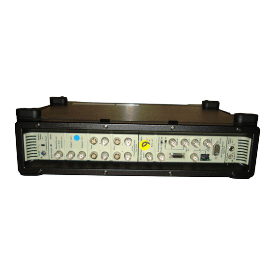
Chapter 5 Data Acquisition Units Portable PULSE Type 3560-B Type 3560-B front-ends comprise a battery/DC-powered 5-channel data acquisition unit. The front-end comes in several versions, as listed in Table 4.1. The front-end is connected to the PC via the LAN Interface located on the front panel. Fig.5.1 Type 3560-B-110 Dyn-X front-end and optional... - Page 64 PULSE Multi-analyzer System Type 3560-B/C/D/E – Installation and IDAe Hardware 5.1.2 Silent Operation Type 3560-B is silent, operating without fans at ambient temperatures up to 35°C (95°F). Above this temperature, the fans start up, but can be switched of from the PULSE software by selecting View, Fan and Battery Control and right-clicking on the frame.
- Page 65 CHAPTER 5 Data Acquisition Units On/Off Button This turns the system on or off. This function may also be controlled by an external voltage supply (see “Follow Ext. Power Switch” below) or by signals received from other front-ends (using the Multi Frame Control (Power On/Off Control) on the Controller module. Follow Ext.
- Page 66 PULSE Multi-analyzer System Type 3560-B/C/D/E – Installation and IDAe Hardware Fig.5.4 How the power and battery status indicators flash for Types 3560-B and 3560-C Battery Driven External Power Driven Off; External power: None Off (standby); External power: Connected Battery not charging Battery charging None None...
-
Page 67: Portable Pulse Type 3560-C
CHAPTER 5 Data Acquisition Units Portable PULSE Type 3560-C Type 3560-C front-ends comprise a battery/DC-powered Type 2827 power supply unit, which can hold one Controller module and one Input/Output module (see Table 4.1). The front-end is connected to the PC via the LAN Interface located on the Controller module. Fig.5.5 Type 3560-C Dyn-X front- end with 5/1-ch. - Page 68 PULSE Multi-analyzer System Type 3560-B/C/D/E – Installation and IDAe Hardware 5.2.3 Silent Operation During operation fans keep the temperature of Type 3560-C within safety limits. In meas- urements where fan noise can influence measurement results (see Table 5.2), the fans can be switched off from the PULSE software by selecting View, Fan and Battery Control and right-clicking on the frame.
- Page 69 CHAPTER 5 Data Acquisition Units • A constant light indicates that the battery is driving the frame The colour indicates the remaining level: from green (full) to red (low) Flashing red indicates that the battery is nearly empty • Rapidly flashing red indicates imminent battery failure Follow Ext.
-
Page 70: Multichannel Portable Pulse Type 3560-D
PULSE Multi-analyzer System Type 3560-B/C/D/E – Installation and IDAe Hardware DC Output To provide power for accessories such as a LAN switch or wireless LAN, the unit is provided with a 5 ± 0.5 and 12 ± 1.0 V DC output (LEMO FGG.00.302 connector) each providing up to 400 mA (1 A fused) –... -
Page 71: Multichannel Pulse Type 3560-E
CHAPTER 5 Data Acquisition Units Table 5.3 dB SPL, dB Lw, Acoustic noise emission A-weighted at 1 m A-weighted of Type 3560-D at 1 m Fan Off Normal (22°C) Max. 5.3.4 DC Output To provide power for accessories such as a LAN switch or wireless LAN, the unit is provided with a 5 ±... - Page 72 PULSE Multi-analyzer System Type 3560-B/C/D/E – Installation and IDAe Hardware 5.4.2 Power Supply Data Acquisition System Type 3560-E must be powered from an external 10 – 32 V DC power supply. This power may be obtained from, for example, a car battery, or it may be powered using the 100 –...
-
Page 73: Power Supply Module Type 2826
CHAPTER 5 Data Acquisition Units Power Supply Module Type 2826 On/Off Button This turns the system on or off. This function may also be controlled by an external voltage supply (see “Follow Ext. Power Switch” below). LEDs Error: Red, indicating, for example, overheating. Switch off the equip- ment and investigate the cause On/Off: Red during power-up, green when all internal voltages are correct Ext. - Page 74 PULSE Multi-analyzer System Type 3560-B/C/D/E – Installation and IDAe Hardware Fuses Two 20 A fuses are provided. One is in the + (positive) line and one in the – (negative) line of the supply (protects against accidental grounding). Chassis Terminal This is connected directly to the chassis ground of the unit.
-
Page 75: Controller And Input/Output Modules
Chapter 6 Controller and Input/Output Modules This chapter describes the controller and input/output modules that may be present in a PULSE system. Features that are common to several of the modules, for example, the Aux. I/O connector present on all controller modules, are described in Chapter 7. With the exception of Types 7533, 3032-A and 3032-B, which are no longer available for sale, full specifications for these modules can be found in the Chapter 11. -
Page 76: Lan Interface Module Type 7533
PULSE Multi-analyzer System Type 3560-B/C/D/E – Installation and IDAe Hardware LAN Interface Module Type 7533 Input 0 Input 0 is equipped with a BNT connector for input of signals in seven ranges from 7.071 mV to 22.36 V in 10 dB steps over the peak frequency range to 25.6 kHz. -
Page 77: 100 Mbit Controller Module Type 7536
CHAPTER 6 Controller and Input/Output Modules RS–232 See section 7.2. 100 Mbit Controller Module Type 7536 LEDs Error: Indicates if an error has occurred in the module. Clock: Indicates the presence of a sampling clock and should always be lit when PULSE software is running. If it is not lit, you cannot make measurements. -
Page 78: 5/1-Ch. Input/Output Controller Modules Types 7537, 7537-A, 3560-B-010, 3560-B-020
PULSE Multi-analyzer System Type 3560-B/C/D/E – Installation and IDAe Hardware 5/1-ch. Input/Output Controller Modules Types 7537, 7537-A, 3560-B-010, 3560-B-020 This module comes in two versions: Type 7537 with LEMO connectors on the input channels and Type 7537-A with BNC connectors. Type 3560-B- 010 is equivalent to Type 7537, while Type 3560-B- 020 is equivalent to Type 7537-A. - Page 79 CHAPTER 6 Controller and Input/Output Modules The LAN RJ-45 connector is used to connect the front-end to LAN systems based on RJ-45 cables. The protocol complies with IEEE 802.3 10 base T. RS–232 See section 7.2. Cable Lock Threaded hole for attaching LAN Cable Holder UA-1617. 6.3.2 Types 7537, 3560-B-010 Input 1 to 5...
-
Page 80: 5/1-Ch. Dyn-X Input/Output Controller Modules Types 7538, 7538-A, 3560-B-110, 3560-B-120
PULSE Multi-analyzer System Type 3560-B/C/D/E – Installation and IDAe Hardware 5/1-ch. Dyn-X Input/Output Controller Modules Types 7538, 7538-A, 3560-B-110, 3560-B-120 This module comes in two versions: Type 7538 with LEMO connectors on the input channels and Type 7538-A with BNC connectors. Type 3560-B- 110 is equivalent to Type 7538, while Type 3560-B- 120 is equivalent to Type 7538-A. - Page 81 CHAPTER 6 Controller and Input/Output Modules RS–232 See section 7.2. Cable Lock Threaded hole for attaching LAN Cable Holder UA-1617. 6.4.2 Types 7538, 3560-B-110 Input 1 to 5 7-pin LEMO connectors (see Fig.7.6 on page 90) for use with Brüel & Kjær microphones. Input may be grounded or floating, controlled by PULSE software.
-
Page 82: 5/1-Ch. Input/Output Controller Modules With Generator Types 7539, 7539-A, 3560-B-030, 3560-B-040
PULSE Multi-analyzer System Type 3560-B/C/D/E – Installation and IDAe Hardware 5/1-ch. Input/Output Controller Modules with Generator Types 7539, 7539-A, 3560-B-030, 3560-B-040 This module comes in two versions: Type 7539 with LEMO connectors on the input channels and Type 7539-A with BNC connectors. Type 3560-B- 030 is equivalent to Type 7539, while Type 3560- B-040 is equivalent to Type 7539-A. - Page 83 CHAPTER 6 Controller and Input/Output Modules The AES/EBU protocol contains both clock and sync. signals as well as power control. See “AES/EBU and Types 7536, 7537, 7538, 7539 and 7540” on page 16. A circular LED around the Multiframe Control BNC socket indicates measurement status (red: digital error;...
-
Page 84: 5/1-Ch. Dyn-X Input/Output Controller Modules With Generator Types 7540, 7540-A, 3560-B-130, 3560-B-140
PULSE Multi-analyzer System Type 3560-B/C/D/E – Installation and IDAe Hardware 5/1-ch. Dyn-X Input/Output Controller Modules with Generator Types 7540, 7540-A, 3560-B-130, 3560-B-140 This module comes in two versions: Type 7540 with LEMO connectors on the input channels and Type 7540-A with BNC connectors. Type 3560-B- 130 is equivalent to Type 7540, while Type 3560- B-140 is equivalent to Type 7540-A. - Page 85 CHAPTER 6 Controller and Input/Output Modules The AES/EBU protocol contains both clock and sync. signals as well as power control. See “AES/EBU and Types 7536, 7537, 7538, 7539 and 7540” on page 16. A circular LED around the Multiframe Control BNC socket indicates measurement status (red: digital error;...
-
Page 86: 6/1-Ch. Input/Output Modules Types 3032-A, 3032-B
PULSE Multi-analyzer System Type 3560-B/C/D/E – Installation and IDAe Hardware 6/1-ch. Input/Output Modules Types 3032-A, 3032-B This module has two versions: Type 3032-A with LEMO and BNT/BNC connectors on the input channels and Type 3032-B with a 37-pin D-sub connector. For input of signals in seven ranges from 7.071 mV to 7.071 V in 10 dB steps over the frequency range... -
Page 87: 6-Ch. Dyn-X Charge & Ccld Input Module Type 3035
CHAPTER 6 Controller and Input/Output Modules 6.7.3 Type 3032-B 37-pin D-sub connector for inputs 1 to 6. See Fig.7.7 on page 91. Type 3032-B does not support the use of microphones that require an external polarization voltage. 6-ch. Dyn-X Charge & CCLD Input Module Type 3035 6-channel Dyn-X Charge &... -
Page 88: 12-Ch. Input Modules Types 3038, 3038-B
PULSE Multi-analyzer System Type 3560-B/C/D/E – Installation and IDAe Hardware 12-ch. Input Modules Types 3038, 3038-B This module comes in two versions: Type 3038 with BNT/BNC connectors on the input channels and Type 3038-B with a two 37-pin D-sub connec- tors. -
Page 89: 6-Ch. Input Modules Types 3039, 3039-B
CHAPTER 6 Controller and Input/Output Modules 6.10 6-ch. Input Modules Types 3039, 3039-B This module comes in two versions: Type 3039 with LEMO and BNT/BNC connectors on the in- put channels and Type 3039-B with a 37-pin D-sub connector. For input of signals in seven ranges from 7.071 mV to 7.071 V in 10 dB steps plus peak... -
Page 90: 12-Ch. Dyn-X Input Modules Types 3040, 3040-B
PULSE Multi-analyzer System Type 3560-B/C/D/E – Installation and IDAe Hardware 6.11 12-ch. Dyn-X Input Modules Types 3040, 3040-B This module comes in two versions: Type 3040 with BNT/BNC connectors on the input channels and Type 3040-B with two 37-pin D-sub connec- tors. -
Page 91: 6-Ch. Dyn-X Input Modules Types 3041, 3041-B
CHAPTER 6 Controller and Input/Output Modules 6.12 6-ch. Dyn-X Input Modules Types 3041, 3041-B This module comes in two versions: Type 3041 with LEMO and BNT/BNC connectors on the in- put channels and Type 3041-B with a 37-pin D- sub connector. For input of signals in one range to 10 V (dynamic range 160 dB) over the frequency peak... -
Page 92: Generator, 4/2-Ch. Input/Output Module Type 3109
PULSE Multi-analyzer System Type 3560-B/C/D/E – Installation and IDAe Hardware 6.13 Generator, 4/2-ch. Input/Output Module Type 3109 Stop BNC connector allowing connection to an emergency stop control, stopping the generators immediately. A simple switch that shorts the signal line to ground will enable this. LEDs Measuring: Indicates a measurement in progress or the downloading of software to the module. -
Page 93: Generator, 2/1-Ch. Input/Output Module Type 3110
CHAPTER 6 Controller and Input/Output Modules Inputs 2 to 4: BNC connectors (see Fig.7.4 on page 89) for direct connection of a voltage signal ® or for connection of CCLD transducers, for example, DeltaTron accelerometers or microphone preamplifiers, and 7-pin LEMO connectors (see Fig.7.6 on page 90) for use with Brüel & Kjær microphones. - Page 94 PULSE Multi-analyzer System Type 3560-B/C/D/E – Installation and IDAe Hardware Each input has one BNT connector (see Fig.7.3 on page 89) and one 7-pin LEMO connector (see Fig.7.6) for input of signals up to a frequency of 204.8 kHz. The BNT connector can be used for direct connection of a voltage signal or connection of CCLD transducers and to provide power for a tacho probe.
-
Page 95: Connectors, Controls And Indicators
Chapter 7 Connectors, Controls and Indicators Aux. I/O This connector is present on all Controller modules and can be used for auxiliary logging, that is, for sampling DC signals 10 times per second. The channels are all single-ended and have six input ranges from 0.1 V to 31.6 V in 10 dB steps. Fig.7.1 10 9 Auxiliary input/output... - Page 96 PULSE Multi-analyzer System Type 3560-B/C/D/E – Installation and IDAe Hardware • Alarm Off – 0V • Alarm On – 5V, • Pin # 9 – Ground • Pin # 10 – DC (out) 1; 100 kΩ pull-up to 5 V •...
-
Page 97: Serial Interface)
CHAPTER 7 Connectors, Controls and Indicators RS–232 (Serial Interface) This 9-pin D-sub connector is present on all controller modules. It is used for setting the IP address and for testing front-end hardware. It also allows communication with an optional Remote Control Unit ZH-0632 for controlling sound intensity measurements. Fig.7.2 RS–232 connector BNT Connector... -
Page 98: Bnc Output Connector
PULSE Multi-analyzer System Type 3560-B/C/D/E – Installation and IDAe Hardware BNC Output Connector Fig.7.5 Signal Output BNC output connector Internal Switch Signal GND (controlled by software) Floating/Grounded Chassis 980319/2 7-pin LEMO Connector Fig.7.6 Pin 1: Calibration output (charge injection calibration check) 7-pin LEMO connector Pin 2: Signal ground... -
Page 99: D-Sub Connectors
CHAPTER 7 Connectors, Controls and Indicators D-sub Connectors Fig.7.7 D-sub connector of Type + Vpre 3032-B CH 1 Lgnd Signal – Vpre Transducer Identification + Vpre CH 2 Lgnd Signal – Vpre Transducer Identification + Vpre CH 3 Lgnd Signal –... - Page 100 PULSE Multi-analyzer System Type 3560-B/C/D/E – Installation and IDAe Hardware Fig.7.8 Dual D-sub connector, inputs 1 to 6 and 7 to 12, of Types 3038-B, 3040-B + Vpre Vpol Transducer Identification CH 1 Lgnd – Vpre Signal Signal – Vpre Lgnd CH 12 Transducer...
-
Page 101: Overload
CHAPTER 7 Connectors, Controls and Indicators Fig.7.9 D-sub connector of Types + Vpre 3039-B, 3041-B CH 1 Lgnd Signal – Vpre Transducer Identification + Vpre CH 2 Lgnd Signal – Vpre Transducer Identification + Vpre CH 3 Lgnd Signal – Vpre Transducer Identification + Vpre CH 4... - Page 102 PULSE Multi-analyzer System Type 3560-B/C/D/E – Installation and IDAe Hardware “Max. Peak Input” chosen in PULSE’s measurement setup. For “out-of-band frequencies”, overload will be indicated for any input level that will cause distortion in the “in-band” range. Caution: In Direct and AC mode, care must be taken when measuring signals with a very high DC component –...
-
Page 103: Cables, Adaptors And Accessories
Chapter 8 Cables, Adaptors and Accessories Signal Cables and Connectors Part No. Description AO-0087-D-xxx Screened Connection Cable, BNC to BNC xxx (length in decimetres) = 012, 020, 030, 050, 060, 070, 080, 100, 125, 150, 180, 200, 220, 250, 300, 350, 400, 500, 750, 800 AO-0090 Adaptor cable, 7-pole Lemo to BNC male, 1.2 m for DeltaTron... - Page 104 PULSE Multi-analyzer System Type 3560-B/C/D/E – Installation and IDAe Hardware Part No. Description Cable, 37-pole D-sub connector to 6 × microdot, PVC AO-0535-D-xxx insulated, 70°C (158°F) xxx (length in decimetres) = 010, 070, 100, 130 Cable, 37-pin D-sub connector to 2 × 4-pin for triaxial AO-0536 accelerometers, 10 m (33 ft.) 85°C (185°F) AO-0562-D-xxx...
- Page 105 CHAPTER 8 Cables, Adaptors and Accessories Part No. Description JJ-0152 BNC T-connector JP-0069 Terminator JP-0145 BNC to 10–32 UNF Plug Adaptor JP-0162 TNC to 10–32 UNF Plug Adaptor WB-1482 Attenuator Adaptor (20 dB) for D-sub connector WB-1497 Attenuator Adaptor (20 dB) for BNC connector Cable, 37-pole D-Sub Socket to 6 ×...
-
Page 106: Lan Accessories
PULSE Multi-analyzer System Type 3560-B/C/D/E – Installation and IDAe Hardware LAN Accessories AO-1449-D-xxx LAN Interface Cable Crossover with RJ45 xxx (length in decimetres) = 005, 010, 020 AO-1450 LAN Interface Cable with RJ45 UA-1617 LAN Cable Relief UL-0190 5 Port Ethernet switch for portable PULSE UL-0229 5-port Gigabit Ethernet Switch WIRELESS LAN... -
Page 107: Power
CHAPTER 8 Cables, Adaptors and Accessories 15 dBi Omni-directional Professional Wireless LAN antenna UL-0231 Note: This item requires a 50 mm diameter pole for mounting, this should be preferably 3 – 4 m high and the antenna should be mounted with the supplied clamps in such a way that only the lowest 15 cm of the antenna unit are obscured by the support pole UL-0232... -
Page 108: Rack Mounting
PULSE Multi-analyzer System Type 3560-B/C/D/E – Installation and IDAe Hardware UA-1590 Fast Charger Kit comprising AC Adaptor ZG-0427 and Rapid Charge Unit ZG-0428 ZG-0429 Power Supply for Type 2827, 100 – 240 V for use with Types 3560-B and 3560-C ZG-0430 Mains Adaptor for Power Supply Module Type 2826 for use with Type 3560-D... -
Page 109: Other Accessories
CHAPTER 8 Cables, Adaptors and Accessories Other Accessories DD-0552 Protection Cover for Type 3560-C DH-0541 Shoulder Strap KE-0439 Suitcase for Type 3560-C and Laptop PC UA-1556 Mounting Kit for Notebook PC UA-1689 Handle for Type 3560-B ZH-0630 Remote Control... - Page 110 PULSE Multi-analyzer System Type 3560-B/C/D/E – Installation and IDAe Hardware...
-
Page 111: Wireless Lan
Chapter 9 Wireless LAN Hardware 9.1.1 Wireless Bridge UL-0230 Fig.9.1 Linksys WET54G Bridge, UL-0230 The Linksys Wireless-G Ethernet Bridge WET54G acts as either an Access Point, Client Point or bridge. The bridge is able to run both 802.11b and 802.11g, meaning 11 Mbit/s and 54 Mbit/s and is suitable for short to medium range. - Page 112 PULSE Multi-analyzer System Type 3560-B/C/D/E – Installation and IDAe Hardware 9.1.2 15 dBi Omnidirectional Antenna Assembly Fig.9.2 Left: UL-0231: 15 dBi Professional Omni Antenna; (Order no. HG2415U-PRO) Top right: UL-0234: Pigtail-cable for Linksys WET54, RPSMA to N-Type Female. Length: 0.5 m (2 feet); (Order no.: CA-RSPNFA002) Bottom Right: UL-0233: N-type male Cable Length: 3 m (10 feet);...
-
Page 113: Additional Accessories
CHAPTER 9 Wireless LAN 9.1.3 8.5 dBi Omnidirectional Magnet-based Car Antenna Assembly Fig.9.3 Left: UL-0232: 8.5 dBi Omni with Magnetic Base, N-Type Male Length 3.5 m (12 feet); (Order no.: HG2409MGU) Right: UL-0234: Pigtail-cable for Linksys WET54, RPSMA to N-Type Female. Length: 0.5 m (2 feet);... -
Page 114: System And Antenna Configurations
PULSE Multi-analyzer System Type 3560-B/C/D/E – Installation and IDAe Hardware 9.2.2 Power Cable from USB port to Wireless Bridge, AQ-1708 With this cable it should be possible to power a wireless bridge from the USB port on the PC. Care should be taken since not all USB ports are capable of providing 500 mA. Cable length: 0.5 m Note: This cable is NOT suited for use with the UL-0230, which uses too much power to be powered from the USB port. -
Page 115: Installing The System
CHAPTER 9 Wireless LAN Fig.9.6 Linksys WET54 to Linksys WET54 Installing the System Please refer to the Linksys manual for system installation – the easiest way is to use the CD-ROM provided. In basic terms, you should go through all the steps in the sections below. -
Page 116: Further Information
PULSE Multi-analyzer System Type 3560-B/C/D/E – Installation and IDAe Hardware 3) Load the CD that came with the system. 4) Change the IP address of the Linksys WET54 to IP: 10.10.10.70. 5) Put a label on the Linksys WET54 with “IP=10.10.10.70”. 6) Disconnect the Linksys WET54. -
Page 117: Calibration
Chapter 10 Calibration 10.1 Why Invest in Calibration? Properly calibrated equipment provides you with confidence that your products/services meet their specifications. Calibration is simply the comparison of instrument performance to a standard of known accuracy. It may simply involve the determination of deviation from nominal, or include correction (adjustment) to minimise the errors. -
Page 118: Available Calibration For Pulse Modules
PULSE Multi-analyzer System Type 3560-B/C/D/E – Installation and IDAe Hardware You can combine a range of services in one agreement running over several years. You get priority at the time you need service. Examples of what a Service Agreement for PULSE can contain are: •... -
Page 119: Reference Instruments - Microphones And Accelerometers
CHAPTER 10 Calibration 10.3.2 Regular Re-Calibration To minimise the cost of errors due to faulty or inaccurate measurements, we can arrange for calibration every year in a ISO 17025 certified laboratory at Brüel & Kjær. With annual data, you will have unbroken history to use as reference, either for internal requirements, for audit required by authorities or at the request of your customers. - Page 120 PULSE Multi-analyzer System Type 3560-B/C/D/E – Installation and IDAe Hardware 10.4.1 Primary Calibration DPLA annually performs hundreds of primary calibrations, on reference microphones and accelerometers, for national metrology institutes, test institutes and for organisations in the industry requiring absolutely minimum variation in sensitivity over time. 10.4.2 Secondary Calibration If your sensitivity requirements are on a step lower than primary calibration, we recommend...
-
Page 121: Specifications
Chapter 11 Specifications Compliance with Standards (For environmental specifications and compliance with standards for PCs, see the specifications given by their respective manufacturers) Valid for Types 3560-B-010, -020, -030, -040, -110, -120, -130, -140, Types 3560-C, 3560-D and 3560-E with Controller Module Type 7536, Input/Output Controller Module Type 7537, 7537-A, 7538, 7538-A, 7539, 7539-A, 7540 or 7540-A Input/Output Module Type 3035, 3038, 3038-B, 3039, 3039-B, 3040, 3040-B, 3041, 3041-B, 3109 or 3110... - Page 122 PULSE Multi-analyzer System Type 3560-B/C/D/E – Installation and IDAe Hardware Mechanical Operating (peak values) −2 MIL−STD − 810C: Vibration: 12.7 mm, 15 ms , 5 − 500 Hz Non-operating: −2 , 10 − 500 Hz IEC 60068−2−6: Vibration: 0.3 mm, 20 ms −2 IEC 60068−2−27: Shock: 1000 ms −2...
- Page 123 CHAPTER 11 Specifications Specifications – Portable PULSE Type 3560-C POWER SUPPLY/FRAME ACOUSTIC NOISE EMISSION (at 1 m) Type 2827 dB SPL, dB Lw, POWER REQUIREMENTS A-weighted at 1 m A-weighted Fulfils the requirements of ISO 7637−1 and 7637−2 Fan Off <17 <25 with batteries...
- Page 124 PULSE Multi-analyzer System Type 3560-B/C/D/E – Installation and IDAe Hardware Specifications – Multichannel PULSE Type 3560-E ® POWER SUPPLY Ext. Power Connector: Neutrik Powercon 3-pole Type 2826 Max. No. of Tacho Probes: 2 in full frame RACK MOUNTING KIT DIMENSIONS WU-0516 Height: 134 mm (5.3″) (3 standard rack-mounting units)
- Page 125 CHAPTER 11 Specifications Specifications – Input Channels, Standard 24-bit and Dyn-X Standard 24-bit Dyn-X 7537/37-A/39/39-A 7538/38-A/40/40-A 3038/38-B/39/39-B 3040/40-B/41/41-B 3560-B-010/020/030/040 3560-B-110/120/130/140 Frequency Range DC to 25.6 kHz 2 × 24-bit A/D Conversion 24-bit Data Transfer 24-bit 16-bit selectable Input Voltage Range 8 ranges: 7.071 mV to 7.07 V peak...
- Page 126 PULSE Multi-analyzer System Type 3560-B/C/D/E – Installation and IDAe Hardware Specifications – Input Channels, Standard 24-bit and Dyn-X (Continued) Standard 24-bit Dyn-X 7537/37-A/39/39-A 7538/38-A/40/40-A 3038/38-B/39/39-B 3040/40-B/41/41-B 3560-B-010/020/030/040 3560-B-110/120/130/140 Spurious-free Input Range Typical Typical Dynamic Range 7.071 mV 110 dB (dB) re full scale input 22.36 mV 110 dB...
- Page 127 CHAPTER 11 Specifications Specifications – Input Channels, Standard 24-bit and Dyn-X (Continued) Standard 24-bit Dyn-X 7537/37-A/39/39-A 7538/38-A/40/40-A 3038/38-B/39/39-B 3040/40-B/41/41-B 3560-B-010/020/030/040 3560-B-110/120/130/140 Sound Intensity Phase Match Complies with IEC 1043 standard Class 1 and ANSI S1.12 – 1995 Class 1 (only for using intensity filter) using Brüel &...
- Page 128 PULSE Multi-analyzer System Type 3560-B/C/D/E – Installation and IDAe Hardware Specifications – Charge Input Channels, Dyn-X (all specifications for transducer capacitance = 1 nF) Dyn-X 3035 (TNC) Frequency Range 0.1 Hz to 25.6 kHz 2 × 24-bit A/D Conversion Data Transfer 24-bit Input Range 2 ranges: 10 nC...
- Page 129 CHAPTER 11 Specifications Specifications – Charge Input Channels, Dyn-X (Continued) (all specifications for transducer capacitance = 1 nF) Dyn-X 3035 (TNC) Harmonic Distortion (all harmonics, all ranges) Guaranteed Typical –80 dB –100 dB @ 1 kHz Crosstalk Frequency Range Guaranteed Typical Between any two channels of a module or between any two 0 –...
- Page 130 PULSE Multi-analyzer System Type 3560-B/C/D/E – Installation and IDAe Hardware Specifications – Input Channels, Types 3109 and 3110 3109 3110 Frequency Range DC to 25.6 kHz DC to 25.6 kHz DC to 204.8 kHz A/D Conversion 16-bit for frequency 16-bit 24-bit range >25.6 kHz Data Transfer...
- Page 131 CHAPTER 11 Specifications Specifications – Input Channels, Types 3109 and 3110 (Continued) 3109 3110 Noise: Measured lin. 10 Hz to 25.6 kHz Measured lin. Measured (input terminated by 10 Hz to 25.6 kHz lin. 10 Hz to 50 Ω or less) 204.8kHz 24-bit ADC 16-bit ADC...
- Page 132 PULSE Multi-analyzer System Type 3560-B/C/D/E – Installation and IDAe Hardware Specifications – Input Channels, Types 3109 and 3110 (Continued) 3109 3110 Crosstalk 7 mV – 7 V Frequency 7 mV – 7 V 22 V Frequency Range Between any two channels of a module Input Range Range Input Range...
- Page 133 CHAPTER 11 Specifications Specifications – Input Channels, Types 3109 and 3110 (Continued) 3109 3110 Common Mode Rejection 7 mV – 7 V 22 V Input Range Input Range Guaranteed Guaranteed Typical Typical 0 – 120 Hz 40 dB, 50 dB at DC 70 dB 80 dB 50 dB...
- Page 134 PULSE Multi-analyzer System Type 3560-B/C/D/E – Installation and IDAe Hardware Specifications – Output Channels, Standard 24-bit and Dyn-X Standard 24-bit Dyn-X 7537/37-A/39/39-A 7538/38-A/40/40-A 1 × BNC Output Connector Output Coupling Signal Ground Coupling Floating or grounded to chassis DA Conversion 24-bit ≤1 mV @ 25C°...
- Page 135 CHAPTER 11 Specifications Specifications – Output Channels, Types 3109 and 3110 3109 3110 2 × BNC 1 × BNC Output Connector Output Coupling Signal Ground Coupling Floating or grounded to chassis DA Conversion 24-bit DC Offset Output Level DC Offset 7 mV –...
- Page 136 PULSE Multi-analyzer System Type 3560-B/C/D/E – Installation and IDAe Hardware Specifications – Output Channels, Types 3109 and 3110 (Continued) 3109 3110 Crosstalk Guaranteed Guaranteed Typical between generator 0 – 2 kHz –100 dB – output and any channel on any 2 kHz –...
- Page 137 CHAPTER 11 Specifications Filter Characteristics Fig.11.1 Characteristics of high-pass filters (–0.1 dB) for all input modules. See also “High-pass Filters” on page 117 0.7 Hz 7.0 Hz Intensity 22.4 Hz 0.01 060127 Fig.11.2 Characteristics of charge high-pass filters, Type 3035 (–10%). See also “High-pass Filters”...
- Page 138 PULSE Multi-analyzer System Type 3560-B/C/D/E – Installation and IDAe Hardware Fig.11.3 Characteristics of charge low-pass filters, Type 3035 (–10%). See also “Low-pass Filters” on page 120 100 Hz 1 kHz 3 kHz 10 kHz 30 kHz 10 k 100 k 060126...
- Page 139 CHAPTER 11 Specifications Specifications – Controller Modules Types 7536, 7537, 7537-A, 7538, 7538-A, 7539, 7539-A, 7540, 7540-A and 5-channel PULSE Data Acquisition Units 3560-B-010, -020, -030, -040, -110, -120, -130, -140 LAN Interface CONNECTOR AUXILIARY I/O RJ 45 (10baseT/100baseTX) connector complying Number of Input Channels: 12 Input Connector: 1 ×...
- Page 140 PULSE Multi-analyzer System Type 3560-B/C/D/E – Installation and IDAe Hardware...
-
Page 141: Service And Repair
Chapter 12 Service and Repair The front-ends and modules that are used in PULSE Systems are designed and constructed to provide you with many years of trouble-free, reliable operation. If a fault occurs however, proceed as follows: Faults that Impair Safety of the System Immediately disconnect the system at its power source (or sources) and secure it against unintended operation. - Page 142 PULSE Multi-analyzer System Type 3560-B/C/D/E – Installation and IDAe Hardware...
-
Page 143: Part Iii: Appendices
Part III Appendices... -
Page 145: Connecting Type 7533
Appendix A Connecting Type 7533 Network Connection using 10 base 2 LAN Interface Module Type 7533 is equipped with a BNC connector for 10 base 2. When connecting the Type 3560-C front-end using this BNC connector, be aware that a cable termination must be used. -
Page 146: Connection Of Synchronization Cables
PULSE Multi-analyzer System Type 3560-B/C/D/E – Installation and IDAe Hardware Connection of Synchronization Cables IDA BNT Using the IDA BNT synchronization you need two cables such as AO-0158, a balanced cable fitted with BNT connectors. Connect the Sync. Out and the Clock Out on the master to the Sync. In and Clock In. on the second frame as shown in Fig.A.2. - Page 147 APPENDIX A Connecting Type 7533 AES/EBU Valid only for Type 7533 version 14.02 or higher. Fig.A.3 50 Ω 50 Ω AES/EBU synchronization Terminator T Connector RG 58 Cable T Connector Terminator method Frontend Frontend 020246/1 Connect a 50 Ω termination (JJ-0052) to a T-connection (JP-0069) and use a RG 58 cable (e.g., AO-0087) as indicated in Fig.A.3.
- Page 148 PULSE Multi-analyzer System Type 3560-B/C/D/E – Installation and IDAe Hardware...
-
Page 149: Specifications Of Discontinued Modules
Appendix B Specifications of Discontinued Modules This appendix contains the specifications of the PULSE modules which are no longer avail- able for sale. Specifications for all other modules can be found in Chapter 11. 10 Mbit LAN Interface Module Type 7533 Input MAX. - Page 150 PULSE Multi-analyzer System Type 3560-B/C/D/E – Installation and IDAe Hardware 10baseT: RJ 45 connector complying with IEEE− Range Equivalent Input Noise 802.3 10baseT 3 μV 7.071 mV PROTOCOL 3 μV 22.36 mV TCP/IP and TCP/UDP 5 μV 70.71 mV ACQUISITION PERFORMANCE 10 μV 223.6 mV Data Transfer rate (No.
- Page 151 APPENDIX B Specifications of Discontinued Modules PRECISION COMPATIBILITY WITH EXISTING TYPE 7533 LAN MODULES Range Precision All Type 7533 10 Mbit LAN modules are compatible and calibrated ±0.5% of reading ±20 mV offset 31.6 V ±0.5% of reading ±7 mV offset 10 V Dimensions ±0.5% of reading ±7 mV offset...
- Page 152 PULSE Multi-analyzer System Type 3560-B/C/D/E – Installation and IDAe Hardware NOISE (10 Hz to 25.6 kHz Terminated with 50 Ω) ANTIALIASING FILTER (@ 32.768 and 65.536 kHz sampling rate) Input Range Equivalent Input Noise Provides at least 80 dB attenuation of those input frequencies which can cause aliasing 3 μV 7.071 mV...
-
Page 153: Appendix C Discontinued Hardware
Appendix C Discontinued Hardware DSP-based Hardware From version 9, PULSE does not support DSP-based hardware, specifically the following types: Multichannel Data Acquisition Unit Types 2816 and Data Acquisition Unit Type 2825 including: • DSP Boards ZD-0812 and ZD-0828 • TAXI Interface Module ZD-0815 •... - Page 154 PULSE Multi-analyzer System Type 3560-B/C/D/E – Installation and IDAe Hardware • No floating ground • No high-pass intensity filter When used alongside 24-bit and Dyn-X modules, Type 3030 will behave like any other module (for example, 3032). However, if channels in the Type 3030 module partici- pate in a measurement, this will, of course, reduce the max.
-
Page 155: Index
Index Numerics Administrator Privileges..........10 AES/EBU...........16, 32, 139 10 base 2 ............2, 137 Air Guide EA-0540 ........... 63 10/100/1000 base T............ 2 Analog Hardware Test..........38 100 Mbit Controller Module Type 7536 ..... 69 Antenna ..............99 12-ch. Dyn-X Input Module ........82 Cable .............. - Page 156 PULSE Multi-analyzer System Type 3560-B/C/D/E – Installation and IDAe Hardware Type 7536 ............69 Controller Modules ........... 67 Generator, 2/1-ch. Input/Output Module ....85 Controls ..............87 Generator, 4/2-ch. Input/Output Module ....84 Copying PULSE Knowledge Library......14 Glossary..............2 Ground Loop Multichannel Structures ........52 Data Acquisition Units ..........
- Page 157 INDEX Multiple Frames Using a Switch ......... 8 Copying to Disk ........... 14 PULSE Services............. 109 Network Factory Defaults............. 6 Rack Mounting ............100 Troubleshooting ........... 40 Rebooting the PC ............. 19 Using 10 base 2..........137 Recommended PC Configuration....... 5 Network Considerations..........
- Page 158 PULSE Multi-analyzer System Type 3560-B/C/D/E – Installation and IDAe Hardware Synchronization Cables ..........16, 32, 138 UDP ................2 Restrictions ...........16, 32 Uninstall PULSE ............12 Unsupported Hardware...........145 User Test Program............41 Tacho Probes ............65 Uses of Dyn-X............51 TCP ................2 Using a Switch ............7 TCP/IP..............2, 40 Testing..............
-
Page 159: Type/Part Number Index
Type/Part Number Index Numerics 7540-A............... 49, 76 2647................97 2647-A ..............97 AO-0087 ..............95 2647-B ..............97 AO-0090 ..............95 2823................ 146 AO-0091 ..............95 2826................65 AO-0158 ..............95 3030................ 145 AO-0414 ..............95 3032-A ............50, 78, 143 AO-0526 .............. - Page 160 PULSE Multi-analyzer System Type 3560-B/C/D/E – Installation and IDA Hardware KQ-0155 ..............100 UL-0232 ..............99 UL-0233-D-030 ............98 UL-0233-D-100 ............98 QB-0048 ..............99 WB-1482 ..............97 UA-1365 ..............49 WB-1497 ..............97 UA-1556 ..............101 WL-1291 ..............97 UA-1572 ..............100 WQ-2575..............98 UA-1590 ..............100 WU-0516..............100 UA-1617 ..............
- Page 162 HEADQUARTERS: DK-2850 Nærum · Denmark · Telephone: +45 4580 0500 · Fax: +45 4580 1405 · www.bksv.com · info@bksv.com Australia (+61) 2 9889-8888 · Austria (+43) 1 865 74 00 · Brazil (+55)11 5188-8161 · Canada (+1) 514 695-8225 China (+86) 10 680 29906 · Czech Republic (+420) 2 6702 1100 · Finland (+358) 9-521 300 · France (+33) 1 69 90 71 00 Germany (+49) 421 17 87 0 ·...
Need help?
Do you have a question about the PULSE 3560-B and is the answer not in the manual?
Questions and answers