Table of Contents
Advertisement
Quick Links
Advertisement
Table of Contents

Related Manuals for THORLABS PDA10PT


Summary of Contents for THORLABS PDA10PT
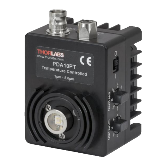
- Page 1 PDA10PT(-EC) Amplified InAsSb Detector User Guide...
-
Page 2: Table Of Contents
4.3. Bandwidth Filter Adjustment ..................6 4.4. Thermoelectric Cooler ....................6 4.5. Light-to-Current Conversion ..................6 Chapter 5 Maintenance ........................7 Chapter 6 Specifications ........................8 Drawings ........................... 12 Chapter 7 Chapter 8 Regulatory ........................13 Chapter 9 Thorlabs Worldwide Contacts ..................14... -
Page 3: Chapter 1 Warning Symbol Definitions
Amplified InAsSb Detector Chapter 1: Warning Symbol Definitions Warning Symbol Definitions Chapter 1 Below is a list of warning symbols you may encounter in this manual or on your device. Symbol Description Direct Current Alternating Current Both Direct and Alternating Current Earth Ground Terminal Protective Conductor Terminal Frame or Chassis Terminal... -
Page 4: Chapter 2 Description
The PDA10PT has two 8-32 (M4) tapped holes for mounting the detector on a Ø1/2" optical post in one of two perpendicular directions. The detector includes a 100 - 240 V, 50 - 60 Hz power supply. -
Page 5: Chapter 3 Setup
1. Unpack the detector head. 2. (Optional) Install a Thorlabs Ø1/2" diameter TR Post (not included) into one of the 8-32 tapped holes (M4 in -EC version) located on the bottom and side of the head, and mount into a optical post holder (sold separately). - Page 6 Amplified InAsSb Detector Chapter 3: Setup 6. Turn on the PDA10PT using the power switch located on the top side of the detector. 7. Install any desired filters, optics, adapters, or fiber adapters to the input aperture. CAUTION The PDA10PT was designed to allow maximum accessibility to the photodetector by having the front surface of the diode flush with the outside of the PDA housing.
-
Page 7: Chapter 4 Operation
LOAD loads. Adjust the gain so that the measured signal level out of the PDA10PT is below 10 V (5 V for a 50 Ω load) to avoid saturation. If necessary, use external neutral density filters to reduce the input light level. The BNC output signal is buffered with an amplifier capable of driving 50 Ω... -
Page 8: Bandwidth Filter Adjustment
Bandwidth Filter Adjustment The PDA10PT also includes an adjustable low-pass filter with settings from 12.5 kHz to 1600 kHz in 8 steps. This filter allows the user to optimize the PDA10PT to operate at the lowest amount of high-frequency optical and electrical noise. -
Page 9: Chapter 5 Maintenance
Chapter 5 There are no serviceable parts in the PDA10PT detector or power supply. The housing may be cleaned by wiping with a soft damp cloth. The window of the detector should only be cleaned using isopropyl alcohol and optical grade wipes. -
Page 10: Chapter 6 Specifications
Operating Temperature All measurements performed with a 50 Ω load unless stated otherwise. The PDA10PT has a 50 Ω series terminator resistor (i.e., in series with amplifier output). This forms a voltage divider with any load impedance (e.g., 50 Ω load divides signal in half). - Page 11 40 dB Figure 3 PDA10PT Photodiode Detectivity (D*) at 0 dB Gain Setting Gain with a 50 Ω load is one-half the Hi-Z gain. NEP values measured using a 50 Ω load and a low-pass filter setting of 1600 kHz; calculated at the detector’s 4.9 µm peak wavelength.
- Page 12 ������ Where A is the area of the photosensitive region of the detector, Δf is the effective noise bandwidth, and NEP is the noise equivalent power of the photodiode. PDA10PT Filter Bandwidth (50 Ω Load) Figure 4 Page 10 TTN010624-D02...
- Page 13 Amplified InAsSb Detector Chapter 6: Specifications Figure 5 Noise Comparison at Min and Max Gain and Filter Settings Figure 6 Wavelength Sensitivity of the Detector at 0 dB Gain Setting Page 11 Rev F, March 11, 2019...
-
Page 14: Chapter 7 Drawings
Amplified InAsSb Detector Chapter 7: Drawings Drawings Chapter 7 Page 12 TTN010624-D02... -
Page 15: Chapter 8 Regulatory
Waste Treatment is Your Own Responsibility If you do not return an “end of life” unit to Thorlabs, you must hand it to a company specialized in waste recovery. Do not dispose of the unit in a litter bin or at a public waste disposal site. -
Page 16: Chapter 9 Thorlabs Worldwide Contacts
Amplified InAsSb Detector Chapter 9: Thorlabs Worldwide Contacts Chapter 9 Thorlabs Worldwide Contacts For technical support or sales inquiries, please visit us at www.thorlabs.com/contact for our most up-to- date contact information. USA, Canada, and South America UK and Ireland Thorlabs, Inc. - Page 17 www.thorlabs.com...
Need help?
Do you have a question about the PDA10PT and is the answer not in the manual?
Questions and answers