Table of Contents
Advertisement
Quick Links
Advertisement
Table of Contents

Related Manuals for THORLABS PDAPC3


Summary of Contents for THORLABS PDAPC3
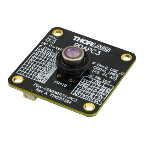
- Page 1 PDAPC3 InGaAs Switchable Gain Photodetector, OEM Package User Guide...
-
Page 3: Table Of Contents
4.5. Terminating Resistance ..........9 4.6. Gain Adjustment ............9 Chapter 5 Troubleshooting ............. 10 Chapter 6 Specifications ..............11 6.1. Response Curve ............12 6.2. Mechanical Drawing ........... 13 Chapter 7 Regulatory ............... 14 Chapter 8 Thorlabs Worldwide Contacts........15... -
Page 5: Chapter 1 Warning Symbol Definitions
InGaAs Switchable Gain Detector, OEM Chapter 1: Warning Symbol Definitions Chapter 1 Warning Symbol Definitions Below is a list of warning symbols you may encounter in this manual or on your device. Symbol Description Direct Current Alternating Current Both Direct and Alternating Current Earth Ground Terminal Protective Conductor Terminal Frame or chassis Terminal... -
Page 6: Chapter 2 Description
Chapter 2: Description Chapter 2 Description The PDAPC3 is an amplified, switchable-gain, Indium Gallium Arsenide (InGaAs) photodetector in an OEM package with an operating wavelength range of 900 to 1700 nm. A DIP switch allows the user to vary the gain in 10 dB steps. A buffered output drives 50 Ω... -
Page 7: Chapter 3 Setup
InGaAs Switchable Gain Detector, OEM Chapter 3: Setup Chapter 3 Setup The pin out table for the on-board header (J2), Figure 1, is shown in the two tables below: Pin 10 Pin 1 Figure 1 J2 Header J2 PIN OUT Designation Designation OUTPUT... - Page 8 Connect a power supply to pins 1, 3, and 5 of the J2 header. The required power supply voltages are: J2 Pin Voltage +12 VDC -12 VDC Thorlabs offers the LD1255-SUPPLY as one compatible power supply option. Connection to the board is shown below: Figure 2 Power Supply Connection Page 4 TTN239792-D02...
- Page 9 InGaAs Switchable Gain Detector, OEM Chapter 3: Setup Digital gain can be adjusted through the J2 header shown in Figure 1 or using the on-board DIP switch shown below. Each switch is ‘Off’/0 when in the up position and ‘On’/1 when in the down position. On-Board DIP Switches Figure 3 Location of the On-Board DIP Switches...
- Page 10 Adjustment Screw Head Figure 4 Side adjusted potentiometer Attach a 50 Ω coax cable to the output of the PDAPC3 detector. Thorlabs offers two suitable cable options, the CA3339 MMCX to BNC cable or the CA3439 MMCX to SMA cable.
- Page 11 25 Ω which could allow ~135 mA of output current. This will damage the output driver of the PDA. Power the PDAPC3 on. When the unit is on, the power indicator LED will be illuminated yellow. If the LED is green or red, this indicates only one power rail, either positive or negative, respectively, is connected.
-
Page 12: Chapter 4 Operation
Chapter 4 Operation 4.1. Theory of Operation Thorlabs PDA series are ideal for measuring both pulsed and CW light sources. The PDAPC3 includes a reverse-biased PIN photodiode, mated to a switchable gain transimpedance amplifier, and packaged in a rugged housing. -
Page 13: Bandwidth And Response
> 5 kΩ) and 5 V for 50 Ω loads. Adjust the gain so that the measured signal level out of the PDAPC3 is below 10 V (5 V with a 50 Ω load) to avoid saturation. For low terminating resistors, <5 kΩ or 1% error, an additional factor needs to be considered. -
Page 14: Chapter 5 Troubleshooting
InGaAs Switchable Gain Detector, OEM Chapter 5: Troubleshooting Chapter 5 Troubleshooting Problem Suggested Solutions Verify that the power is switched on and all connections are secure. Verify the proper terminating resistor is installed if using a Voltage measurement device. There is no signal response. Verify that the optical signal wavelength is within the specified wavelength range. -
Page 15: Chapter 6 Specifications
±12 mV (Max) ±12 mV (Max) The PDAPC3 has a 50 Ω series terminator resistor (i.e. in series with amplifier output). This forms a voltage divider with any load impedance (e.g. 50 Ω load divides signal in half). Rev A, May 7, 2021... -
Page 16: Response Curve
InGaAs Switchable Gain Detector, OEM Chapter 6: Specifications Electrical Specifications Detector InGaAs Active Area Ø1.0 mm (0.8 mm λ Wavelength Range 900 to 1700 nm λ Peak Wavelength 1550 nm (Typ.) ( λ Peak Response 1.05 A/W (Typ.) Amplifier GBP 600 MHz 50 Ω... -
Page 17: Mechanical Drawing
InGaAs Switchable Gain Detector, OEM Chapter 6: Specifications 6.2. Mechanical Drawing Rev A, May 7, 2021 Page 13... -
Page 18: Chapter 7 Regulatory
Waste Treatment is Your Own Responsibility If you do not return an “end of life” unit to Thorlabs, you must hand it to a company specialized in waste recovery. Do not dispose of the unit in a litter bin or at a public waste disposal site. -
Page 19: Chapter 8 Thorlabs Worldwide Contacts
InGaAs Switchable Gain Detector, OEM Chapter 8: Thorlabs Worldwide Contacts Chapter 8 Thorlabs Worldwide Contacts For technical support or sales inquiries, please visit us at www.thorlabs.com/contact for our most up-to-date contact information. USA, Canada, and South America UK and Ireland Thorlabs, Inc. - Page 20 www.thorlabs.com...
Need help?
Do you have a question about the PDAPC3 and is the answer not in the manual?
Questions and answers