
Related Manuals for VWR avantor PH-2500L


Summary of Contents for VWR avantor PH-2500L
- Page 1 Instruction manual ® pH-METER PH-2500L EU cat. no 662-2380 Version 1.1 Issue: 12.2021...
- Page 2 Legal address of Manufacturer Europe VWR International bv, Researchpark Haasrode 2020 Geldenaaksebaan 464 B-3001 Leuven +3216385011 be.vwr.com UK Importer: VWR International Ltd Hunter Boulevard, Magna Park Lutterworth, Leicestershire, LE17 4XN uk.vwr.com Country of Origin POLAND...
-
Page 3: Table Of Contents
CONTENT I. Introduction........................1 1. Package content......................2 2. Disclaimer........................2 3. Characteristics of the meter..................3 4. The outside view......................4 5. The meter‘ s maintenance..................6 6. Switching the meter on and off...................7 6.1. Choosing the measurement function..............8 6.2. Stabilised reading.....................9 7. Preparation to work....................9 7.1. - Page 4 18.3. Collecting measurement series..............39 18.4. Mode of holding readings (HOLD)..............40 18.5. Viewing the readings..................41 19. Calibration report....................42 20. Communication with a PC..................42 21. Technical data......................44 22. Ordering information....................45 23. Technical service....................46 24. Warranty.........................46 25. Equipment disposal....................47...
-
Page 5: Introduction
- 1 - INTRODUCTION... -
Page 6: Package Content
- 2 - PACKAGE CONTENT 1. PH-2500L pH meter. 2. Glass combination pH electrode. 3. Stainless steel temperature sensor 4. pH 4,00, pH 7,00, pH 10,00 buffer solution, 50 ml each. 5. Electrolyte – saturated KCl – 50 ml. 6. 5V/1000mA power adapter. 7. -
Page 7: Characteristics Of The Meter
- 3 - CHARACTERISTICS OF THE METER PH-2500L waterproof pH-meter belongs to the newest generation of measuring devices. The meter provides high accuracy and repeatability of readings. The meter’s memory is independent from power supply. The meter is equipped with a large backlit custom LCD, which can simultaneously display pH and temperature readings. -
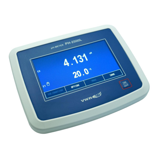
Page 8: The Outside View
- 4 - THE OUTSIDE VIEW On the front wall of the meter there is a graphic LCD placed (Pic. 1), on which the following readings are displayed: pH or redox potential in mV units; temperature. At the top of the LCD the current time and date are displayed. Choosing particular functions is described in the chapter 17.1. - Page 9 - 5 - button (Pic. 2) placed below the display is used for switching the meter on and off. In the back wall of the meter the sockets are placed with the symbols given below: pH/mV BNC-50 socket for connecting the combination pH or redox electrode;...
-
Page 10: The Meter' S Maintenance
- 6 - THE METER‘ S MAINTENANCE The meter is equipped with a graphic touchscreen. The maintenance consists in pressing particular keys and windows which appear on the screen. Grey captions in the windows and keys inform that these elements are not active in this particular operating mode. -
Page 11: Switching The Meter On And Off
- 7 - SWITCHING THE METER ON AND OFF After switching the meter on with the button, the memory test proceeds. If the test ends successfully, the meter enters the measurement screen with settings entered before previous switching it off. In case of detecting the manufacturer‘s calibration data loss, the following information will appear: Pressing the button accepts standard manufacturer‘s calibration... -
Page 12: Choosing The Measurement Function
- 8 - 6.1. Choosing the measurement function The user may choose the reading to be displayed on the measuring screen: pH or redox potential. To choose, on the measuring screen press the button, the option screen will display with the tab open containing FUNCTION the previously set configuration (Pic. -
Page 13: Stabilised Reading
- 9 - 6.2. Stabilised reading The stabilised reading signalisation is active only for the reading marked with a frame. If the measured value meets the criterium of the stabilised reading, it is signalised by green colour of the frame and additionally with a sound if it has been activated. -
Page 14: Ph Measurement
- 10 - pH MEASUREMENT User‘s manual for PH-2500L pH meter v1.0x... -
Page 15: Preparation Of The Ph Electrode
- 11 - PREPARATION OF THE pH ELECTRODE The electrode should be prepared to work according to the manufacturer’s instructions. It is especially important to keep the membrane active and clean, rinse it accurately after each measurement and dry it gently with a tissue paper. -
Page 16: Resolution
- 12 - When the parameters are set, return to the measurement screen by pressing button. 9.1. Resolution The reading can be displayed with low or high resolution. By pressing the RESOLUTION window, choose: - 0.01 pH measurement resolution; - 0.001 pH measurement resolution. 9.2. -
Page 17: Calibration Solution
- 13 - 9.3. Calibration solution Displays types of calibration solutions applied for the last calibration: - calibration with manually entered buffers‘ values; - calibration with automatic correction of the standards‘ values. Calibration in buffers and standards is described in detail in the chapter 10. The types of calibration solutions are stored for each of the three electrodes separately and may be changed only in the calibration mode (point 10.2). -
Page 18: Calibration
- 14 - 10. CALIBRATION Before starting measurement with a new electrode or before making measurements which require high accuracy, the electrode connected to the meter should be calibrated. Results of measurements made without calibration will be burdened with a significant error. Calibration is performed in the buffer or standard solutions. -
Page 19: Calibration In Buffer Or Standard Solutions
- 15 - Calibration with use of one solution does not guarantee high accuracy. If only one solution is used, its value should be close to the anticipated value of the measured solution. If the required accuracy isn’t very high and the measurements are made in the whole range, 1-point calibration should be performed with use of solution close to 7.00 pH. -
Page 20: Entering The Buffers' Values Into The Meter's Memory
- 16 - 10.2. Entering the buffers’ values into the meter’s memory If the calibration with use of buffers has been chosen and the pH values set by the manufacturer are used, there is no need to change them. However, it should be verified whether the values correspond to those of applied buffers. - Page 21 - 17 - Pic. 6 Each of the calibration points has its own range of pH buffers values to enter. This limitation enables automatic detection of the buffer solutions by the meter. Table 1 contains the manufacturer’s settings of the pH buffer solutions values used for calibration.
-
Page 22: Calibration In Buffer Solutions
- 18 - The meter takes into consideration only the values detected during calibration. The pH values set in unused calibration points do not affect the calibration results. During next calibrations there is no need to perform the actions described above, provided that the previously used buffer solutions haven’t been changed. - Page 23 - 19 - Pic. 7. If the meter is unable to detect the buffer‘s value, it will signalise the error after pressing the button with a triple warning sound. In such case check the solution value or the electrode which may be broken. Only the pH buffers values detected during calibration are calculated, any other values recorded earlier do not influence the reading.
-
Page 24: Calibration With Use Of Standard Solutions
- 20 - After finishing calibration in the first buffer rinse the electrode and temperature probe in distilled water and dry them with tissue paper and start calibration in next buffers (Pic. 7.C) by repeating the last point of the activities described above. -
Page 25: Calibration With Manual Temperature Compensation
- 21 - When the reading stabilises, press the button. Next to the detected buffer value the marking will appear, what informs that the calibration value has been recorded. Simultaneously, the measurement value will be adjusted to the detected buffer value. If the reading is still different than the solution value, wait until the reading stabilises and press the button again. -
Page 26: Checking The Electrode Condition
- 22 - 11. CHECKING THE ELECTRODE CONDITION After pH electrode calibration the meter calculates its parameters: offset in pH units and slope defined also as efficiency in precents. The electrode offset may be defined in pH or mV units. An ideal electrode immersed in the 7.00 pH buffer before calibration should indicate 7.00 pH which equals 0.00 mV. -
Page 27: Ph Measurement
- 23 - 12. pH MEASUREMENT Before starting measurement the meter and the pH electrode have to be prepared for work (chapters 7 and 8 respectively). Good condition of the electrode is crucial for correct readings. If the electrode is calibrated, choose its number according to the section 9.2 and the measurement resolution according to the section 9.1. -
Page 28: Measurement With Manual Temperature Compensation
- 24 - 12.2. Measurement with manual temperature compensation Disconnecting the temperature probe from the meter switches the meter to the manual temperature compensation mode. Next to the entered (not measured) temperature value, instead of the symbol, the symbol is displayed (Pic. -
Page 29: Redox Potential And Temperature Measurement
- 25 - III. REDOX POTENTIAL AND TEMPERATURE MEASUREMENT... -
Page 30: Setting The Redox Potential Parameters
- 26 - 13. SETTING THE REDOX POTENTIAL PARAMETERS The redox potential (ORP) parameters window is entered by selecting the redox potential reading (a frame will be displayed around it – Pic. 9A) and the button. The screen (Pic. 9B) enables choosing the resolution, the reference temperature and setting the zero offset for the relative measurement. -
Page 31: Resolution
- 27 - After setting the parameters return to the measurement screen by pressing button. If the relative measurement has been chosen, next to the redox value the Rel symbol (Relative) will appear (Pic. 9C). The difference between the redox potential value and the reference value is displayed. -
Page 32: Redox Potential Measurement
- 28 - 14. REDOX POTENTIAL MEASUREMENT PH-2500L is an accurate voltmeter. The measurement may be made with redox electrode or during titration. To make measurement: - turn the meter on by pressing the button; - choose the redox potential measurement to be displayed on the measuring screen according to the point 17.1;... -
Page 33: Setting The Temperature Measurement Parameters
- 29 - 15. SETTING THE TEMPERATURE MEASUREMENT PARAMETERS The temperature measurement parameters window is entered by selecting the temperature reading (Pic. 11A) and next the button (Pic. 11B). The screen enables choosing resolution, probe group, unit and entering the manual temperature compensation value. -
Page 34: Probe Number
- 30 - 15.2. Probe number The meter may store parameters of three probes, which may be replaced without the need of entering the group again, only the number which symbolises the sensor group has to be selected. By pressing the PROBE NO. -
Page 35: Temperature Measurement
- 31 - 16. TEMPERATURE MEASUREMENT Follow the instructions: - turn the meter on by pressing the button - connect the temperature probe to the RCA (Chinch) socket, the symbol will appear on the screen; - immerse the temperature probe into the solution; - wait till the value stabilises and read the result. -
Page 36: Options
- 32 - OPTIONS User‘s manual for PH-2500L pH meter v1.0x... -
Page 37: Option Screen
- 33 - 17. OPTION SCREEN Enter the screen by pressing the button in the measurement OPTION screen. The screen contains the following tabs: OPTION - choose the measurement functions to be displayed on the FUNCTION measurement screen; - parameters for collecting measurement series; SERIES - choose the language, set the economical mode, time and MISCELLANEOUS... -
Page 38: Series
- 34 - 17.2. Series For the description of the tab, see the chapter 18. SERIES 17.3. Miscellaneous On this screen (Pic. 14A) the following parameters may be entered: LANGUAGE - choosing the language: English, German, French, Spanish, Italian, Portuguese (Pic. 14B); SOUND - turning the buttons sound on / off;... - Page 39 - 35 - Pic. 14...
-
Page 40: Info
- 36 - To enter a logical value (language, sound, brightness), press the chosen window, a table will appear to choose the value. To enter a numerical value, press the chosen window, a numerical keyboard will appear to enter the value and confirm with the button. -
Page 41: Recording The Readings, Memory Readout
- 37 - 18. RECORDING THE READINGS, MEMORY READOUT The meter enables recording 500 readings of the displayed measurement functions. The readings are stored in memory independently from power supply. Before the measurement set the storage parameters for the readings. 18.1. -
Page 42: Entering Single Readings Into The Memory
- 38 - To enter the interval or number of samples, press the chosen window, a numerical keyboard will appear to enter the value and confirm with the button. If in the position is set to , the MODE STOP INTERVAL NUMBER OF positions are unavailable. -
Page 43: Collecting Measurement Series
- 39 - 18.3. Collecting measurement series There is a possibility to automatically store series of measurements in the meter’s memory. Follow the instructions: - choose automatic collection of readings (point 18.1); - enter the time interval and number of samples (point 18.1); - return to the measurement screen with the button;... -
Page 44: Mode Of Holding Readings (Hold)
- 40 - 18.4. Mode of holding readings (HOLD) If in the position option has been chosen, than on the measuring MODE STOP screen in the place of the button the button will appear. Pressing this button holds all the readings, the green frame displays around them and the button appears at the bottom of the screen (Pic. -
Page 45: Viewing The Readings
- 41 - 18.5. Viewing the readings The stored readings may be viewed on the meter‘s screen. Follow the instructions: - on the measurement screen press the button and choose the tab on the option screen; MEMORY - press the button. -
Page 46: Calibration Report
- 42 - 19. CALIBRATION REPORT During calibration process in each of the measurement functions the meter creates a calibration report, which includes information about calibration points, measurement results in these points and calculated parameters as: efficiency and offset of the pH electrode and K constant of the conductivity cell. - Page 47 - 43 - - "Download calibration data" enables downloading the calibration data from the meter. Choose the measuring function in the meter to collect its report. In this option choose: „Name“ - the meter's name will be given to each report. At least one of the other following options needs to be selected with this one;...
-
Page 48: Technical Data
- 44 - 21. TECHNICAL DATA pH MEASUREMENT: accuracy range resolution (±1 digit) -6.000 20.000 pH 0.001 / 0.01 pH ±0.002 pH >10 12 W Input impedance: Temperature compensation: manual/automatic Compensation range: -5.0 ÷ 110.0 pH electrode calibration: automatic, in 1 ... -
Page 49: Ordering Information
- 45 - 22. ORDERING INFORMATION EPH-1 standard glass pH electrode & 1 meter cable 662-2381 REG-1 glass ORP (redox) electrode 1 meter cable 662-2357 TS-2B stainless steel temperature sensor 1meter cable 442-1264 Buffer solutions, 20 °C AVS TITRINORM: pH 4 100 ml plastic bottles 32095.184 500 ml plastic bottles... -
Page 50: Technical Service
The customer is responsible for applying for and obtaining the necessary regulatory approvals or other authorisations necessary to run or use the Product in its local environment. VWR will not be held liable for any related omission or for not obtaining the required approval or authorisation, unless any refusal is due to a defect of the product. -
Page 51: Equipment Disposal
- 47 - 25. EQUIPMENT DISPOSAL This equipment is marked with the crossed out wheeled bin symbol to indicate that this equipment must not be disposed of with unsorted waste. Instead it's your responsibility to correctly dispose of your equipment at lifecycle -end by handling it over to an authorized facility for separate collection and recycling. - Page 52 - 48 - Your Distributor Austria Hungary Poland VWR International GmbH VWR International Kft. VWR International Sp. z o.o. Graumanngasse 7 Simon László u. 4. Limbowa 5 1150 Vienna 4034 Debrecen 80-175 Gdansk Tel.: +43 1 97 002 0 Tel.: +36 (52) 521-130 Tel.: +48 058 32 38 210...
Need help?
Do you have a question about the avantor PH-2500L and is the answer not in the manual?
Questions and answers