
Related Manuals for VWR avantor CO-2500L


Summary of Contents for VWR avantor CO-2500L
- Page 1 Instruction manual ® CONDUCTIVITY METER CO-2500L EU cat. no 663-0372 Version 1.1 Issue: 12.2021...
- Page 2 Legal address of Manufacturer Europe VWR International bv, Researchpark Haasrode 2020 Geldenaaksebaan 464 B-3001 Leuven +3216385011 be.vwr.com UK Importer: VWR International Ltd Hunter Boulevard, Magna Park Lutterworth, Leicestershire, LE17 4XN uk.vwr.com Country of Origin POLAND...
-
Page 3: Table Of Contents
CONTENT I. Introduction........................1 1. Package content......................2 2. Disclaimer........................2 3. Characteristics of the meter..................3 4. The outside view......................4 5. The meter‘s maintenance...................6 6. Switching the meter on and off...................7 6.1. Stabilised reading.....................8 7. Preparation to work....................9 7.1. Choosing the kind of the temperature compensation........9 II. - Page 4 17. Recording the readings, memory readout..............41 17.1. Storage parameters..................41 17.2. Entering single readings into the memory............42 17.3. Collecting measurement series..............43 17.4. Mode of holding readings (HOLD)..............44 17.5. Viewing the readings..................45 18. Calibration report....................46 19. Communication with a PC..................46 20. Technical data......................48 21.
-
Page 5: Introduction
- 1 - INTRODUCTION... -
Page 6: Package Content
- 2 - PACKAGE CONTENT 1. CO-2500L conductivity meter. 2. Stainless steel temperature sensor 3. Plastic body, metal electrodes conductivity cell. 4. 12,90 mS/cm conductivity controlling solution – 50 ml. 5. 5V/1000mA power adapter. 6. Free standing electrode holder. 7. USB cable for connecting with a PC 8. -
Page 7: Characteristics Of The Meter
- 3 - CHARACTERISTICS OF THE METER CO-2500L waterproof conductivity meter belongs to the newest generation of measuring devices. The meter provides high accuracy and repeatability of readings. The meter’s memory is independent from power supply. The meter is equipped with a large backlit custom LCD, which can simultaneously display conductivity and temperature readings. -
Page 8: The Outside View
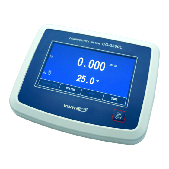
- 4 - THE OUTSIDE VIEW On the front wall of the meter there is a graphic LCD placed (Pic. 1), on which the following readings are displayed: conductivity or salinity, TDS, resistivity; temperature. At the top of the LCD the current time and date are displayed. Choosing particular functions is described in the chapter 16.1. - Page 9 - 5 - button (Pic. 2) placed below the display is used for switching the meter on and off. In the back wall of the meter the sockets are placed with the symbols given below: temp RCA (Chinch) socket to connect the temperature probe; cond BNC-50 socket for connecting the conductivity cell.
-
Page 10: The Meter's Maintenance
- 6 - THE METER‘S MAINTENANCE The meter is equipped with a graphic touchscreen. The maintenance consists in pressing particular keys and windows which appear on the screen. Grey captions in the windows and keys inform that these elements are not active in this particular operating mode. -
Page 11: Switching The Meter On And Off
- 7 - SWITCHING THE METER ON AND OFF After switching the meter on with the button, the memory test proceeds. If the test ends successfully, the meter enters the measurement screen with settings entered before switching it off previously. In case of detecting the manufacturer‘s calibration data loss, the following information will appear: Pressing the button accepts standard manufacturer‘s calibration... -
Page 12: Stabilised Reading
- 8 - 6.1. Stabilised reading The stabilised reading signalisation is active only for the reading marked with a frame. If the measured value meets the criterium of the stabilised reading, it is signalised by green colour of the frame and additionally with a sound if it has been activated. -
Page 13: Preparation To Work
- 9 - PREPARATION TO WORK Before starting work: connect the power adapter to the power socket; - connect conductivity cell to the cond (BNC-50) socket; - in case of using the temperature probe connect it to the temp (RCA) temperature socket;... -
Page 14: Conductivity And Salinity Measurement
- 10 - CONDUCTIVITY AND SALINITY MEASUREMENT User‘s manual for CO-2500L conductivity meter v1.0x... -
Page 15: Entering The Conductivity Parameters
- 11 - ENTERING THE CONDUCTIVITY PARAMETERS Before starting calibration and measurements it is necessary to perform all activities described in the chapter 7. Additionally, according to the chapter below, it is necessary to choose the unit in which the calibration and measurement are going to be made. -
Page 16: Resolution
- 12 - When the parameters are entered, return to the measurement screen by pressing the button. 8.1. Resolution The reading may be displayed with low or high resolution. After pressing the RESOLUTION window, choose: - 3½ digit measurement resolution; - 4½... - Page 17 - 13 - Pic. 5 Choose the unit by pressing the relevant window. In case of choosing S/cm and * cm unit, at the bottom of the screen the position and the window with the chosen compensation COMPENSATION mode with appear. In case of measurements in g/l NACL, % NACL, g/l KCL, % KCL, g/l TDS, % TDS units, the position does not appear.
-
Page 18: Calibration Points And Date
- 14 - 8.4. Calibration points and date Pressing the button opens a screen (Pic. 5C) which displays calibration modes, calibration points, K constant in these points, calibration validity time and the last calibration date. In the calibration mode MANUAL only P1 point is active. -
Page 19: Entering The A Coefficient
- 15 - Entering the a coefficient 8.7. The a coefficient range in CO2500L is 0 ÷ 10.00 % / C with accuracy 0.01 % / C. Generally for measurements, the most frequently applied temperature compensation coefficient is equal a = 2 % / C. -
Page 20: Maintenance Of The Conductivity Cell
- 16 - MAINTENANCE OF THE CONDUCTIVITY CELL The delivered in the set conductivity cell with a range 0 ÷ 400 mS/cm is sufficient for measurements in almost every type of liquids with maximal concentration. Metal electrodes are easy to clean and plastic body provides higher durability. -
Page 21: Calibration
- 17 - 10. CALIBRATION A characteristic feature of every conductivity cell is its K constant. Before the result is displayed, the measured value is multiplied by the K constant value. In practice, the K constant is determined by calibration in standard solution. The user may calibrate in two ways: by entering known K constant value (given by the cell’s manufacturer) or by determining it with use of a standard solution. -
Page 22: Calibration Without Standard Solution
- 18 - Entering the calibration mode irreversibly erases the cell’s K constant stored under the chosen cell number. In case of choosing the cell number, entering and escaping the calibration mode not having made calibration, the previously stored K constant will be deleted and K = 1 cm constant will be adopted. -
Page 23: Calibration With Use Of Standard Solution
- 19 - Pic. 6. 10.2. Calibration with use of standard solution The K constant of the conductivity cell changes with the conductivity value of the measured solution. The purpose of multi-point calibration is to suppress this effect. The meter enables 3-point calibration in freely chosen standard solutions. -
Page 24: Entering The Standard Solution Value
- 20 - To obtain accurate results of calibration, comply to the following principles: 1. For multi-point calibration start with the standard solution of the lowest conductivity value and end with one of the highest. 2. The temperature of the standards should be equal to the reference temperature (the most frequently it is 25 3. -
Page 25: Calibration With Automatic Temperature Compensation
- 21 - Pic. 7. 10.2.2. Calibration with automatic temperature compensation Follow the instructions: - choose the cell number (E1, E2 or E3), according to the point 8.2; - connect the conductivity cell and the temperature probe; - enter the calibration mode: on the measurement screen select the conductivity measurement, press and hold the button until the background changes colour to red, the meter will automatically change... - Page 26 - 22 - Pic. 8. Blinking frame around the calibration point informs, that the difference between the reading and the standard is significant, the meter will signalise the error with a triple warning sound after pressing the button. When the calibration process is finished, the meter is ready for the measurement.
-
Page 27: Calibration With Manual Temperature Compensation
- 23 - 10.2.3. Calibration with manual temperature compensation To calibrate the meter: - disconnect the temperature probe; - measure the temperature of the solution with a laboratory thermometer and enter its value according to section 14.5; - enter the calibration mode: select the conductivity measurement on the measurement screen, press and hold the button until the background changes colour into red, the meter will automatically change... - Page 28 - 24 - Pic. 9 Blinking frame around the calibration point informs, that the difference between the reading and the standard is significant, the meter will signalise the error with a triple warning sound after pressing the button. When the calibration process is finished, the meter is ready for the measurement.
-
Page 29: Conductivity Measurement
- 25 - 11. CONDUCTIVITY MEASUREMENT 11.1. Measurement without temperature compensation An accurate conductivity measurement should be performed without the temperature compensation. The measured solution should be adjusted to the reference temperature chosen earlier (25 °C or 20 °C), with use of the temperature measurement provided by the meter. -
Page 30: Measurement With Automatic Temperature Compensation
- 26 - 11.2. Measurement with automatic temperature compensation Follow the instructions: connect the conductivity cell and the temperature probe to the Con and t sockets respectively (Pic. 2); turn the meter on with choose the conductivity measurement mode (section 8.3); if the conductivity cell is not calibrated, calibrate it (chapter 10);... -
Page 31: Measurement With Manual Temperature Compensation
- 27 - 11.3. Measurement with manual temperature compensation Measurement with manual temperature compensation may be performed in stable working conditions, i.e., measurements in laboratory, especially with use of thermostat, or in case of the temperature probe breakdown. Disconnecting the temperature probe switches the meter to manual temperature compensation. -
Page 32: Salinity And Total Dissolved Solids Measurement
- 28 - 12. SALINITY AND TOTAL DISSOLVED SOLIDS MEASUREMENT Salts and minerals dissolved in natural water influence the conductivity, which in principle is proportional to the quantity of dissolved substances. This dependence enables to determine, after certain calculations, salinity of the measured solution in concentration units (g/l or %), or to determine the TDS (Total Dissolved Solids). -
Page 33: Salinity Measurement With Conversion To Nacl Or Kcl
- 29 - The results are more accurate for homogeneous solutions (NaCl, KCl). Concentration of salts mixture with unknown composition in most cases is counted to NaCl. The usefulness of water for home or industry is usually checked by determining of TDS. It is possible to determine the approximate Total Dissolved Solids content using the conductivity reading on the assumption that the salt’s composition in the taken samples has not been changing significantly. -
Page 34: Notices About Temperature Compensation
- 30 - 13. NOTICES ABOUT TEMPERATURE COMPENSATION 13.1. Natural water The meter enables reduction of the temperature compensation error in case measurements natural water with conductivity range 60 µS/cm ÷ 1 mS/cm. Natural water is the surface water and the ground water. - Page 35 - 31 - In case of water with conductivity C=0.5µS/cm at 25 ºC the α coefficient values at other temperature are as follows: T=26.0ºC T=50.0ºC T=69.9ºC conductivity α coef. conductivity α coef. conductivity α coef. 0.532µS/cm 5.81% 1.50µS/cm 8.55% 3.20µS/cm 11.96% 0.512µS/cm 2.07%...
-
Page 36: Temperature Measurement
- 32 - III. TEMPERATURE MEASUREMENT User‘s manual for CO-2500L conductivity meter v1.0x... -
Page 37: Setting The Temperature Measurement Parameters
- 33 - 14. SETTING THE TEMPERATURE MEASUREMENT PARAMETERS The temperature measurement parameters window is entered by selecting the temperature reading (Pic. 13A) and next the button (Pic. 13B). The screen enables choosing resolution, probe group, unit and entering the manual temperature compensation value. -
Page 38: Probe Number
- 34 - 14.2. Probe number The meter may store parameters of three probes, which may be replaced without the need of entering the group again, only the number which symbolises the sensor group has to be selected. By pressing the PROBE NO. -
Page 39: Temperature Measurement
- 35 - 15. TEMPERATURE MEASUREMENT Follow the instructions: - turn the meter on by pressing the button - connect the temperature probe to the RCA (Chinch) socket, the symbol will appear on the screen; - immerse the temperature probe into the solution; - wait till the value stabilises and read the result. -
Page 40: Options
- 36 - IV. OPTIONS User‘s manual for CO-2500L conductivity meter v1.0x... -
Page 41: Option Screen
- 37 - 16. OPTION SCREEN Enter the screen by pressing the button in the measurement OPTION screen. The screen contains the following tabs: OPTION - choose the measurement functions to be displayed on the FUNCTION measurement screen; - parameters for collecting measurement series; SERIES - choose the language, set the economical mode, time and MISCELLANEOUS... -
Page 42: Series
- 38 - 16.2. Series For the description of the tab, see the chapter 17. SERIES 16.3. Miscellaneous On this screen (Pic. 16A) the following parameters may be entered: LANGUAGE - choosing the language: English, German, French, Spanish, Italian, Portuguese (Pic. 16B); SOUND - turning the buttons sound on / off;... - Page 43 - 39 - Pic. 16...
-
Page 44: Info
- 40 - To enter a logical value (language, sound, brightness), press the chosen window, a table will appear to choose the value. To enter a numerical value, press the chosen window, a numerical keyboard will appear to enter the value and confirm with the button. -
Page 45: Recording The Readings, Memory Readout
- 41 - 17. RECORDING THE READINGS, MEMORY READOUT The meter enables recording 500 readings of the displayed measurement functions. The readings are stored in memory independently from power supply. Before the measurement set the storage parameters for the readings. 17.1. -
Page 46: Entering Single Readings Into The Memory
- 42 - To enter the interval or number of samples, press the chosen window, a numerical keyboard will appear to enter the value and confirm with the button. If in the position is set to , the MODE STOP INTERVAL NUMBER OF positions are unavailable. -
Page 47: Collecting Measurement Series
- 43 - 17.3. Collecting measurement series There is a possibility to automatically store series of measurements in the meter’s memory. Follow the instructions: - choose automatic collection of readings (point 17.1); - enter the time interval and number of samples (point 17.1); - return to the measurement screen with the button;... -
Page 48: Mode Of Holding Readings (Hold)
- 44 - 17.4. Mode of holding readings (HOLD) If in the position option has been chosen, than on the measuring MODE STOP screen in the place of the button the button will appear. Pressing this button holds all the readings, the green frame displays around them and the button appears at the bottom of the screen (Pic. -
Page 49: Viewing The Readings
- 45 - 17.5. Viewing the readings The stored readings may be viewed on the meter‘s screen. Follow the instructions: - on the measurement screen press the button and choose the tab on the option screen; MEMORY - press the button. -
Page 50: Calibration Report
- 46 - 18. CALIBRATION REPORT During calibration process in each of the measurement functions the meter creates a calibration report, which includes information about calibration points, measurement results in these points and calculated parameters as: efficiency and offset of the pH electrode and K constant of the conductivity cell. - Page 51 - 47 - - "Download calibration data" enables downloading the calibration data from the meter. Choose the measuring function in the meter to collect its report. In this option choose: „Name“ - the meter's name will be given to each report. At least one of the other following options needs to be selected with this one;...
-
Page 52: Technical Data
- 48 - 20. TECHNICAL DATA CONDUCTIVITY MEASUREMENT: accuracy ranges resolution frequency (±1 digit) 0.000 ÷ 19.999 mS/cm 0.001 / 0.01 mS/cm ±0.1 % 100 Hz 20.00 ¸ 199.99 mS/cm 0.01 / 0.1 mS/cm ±0.1 % 1 kHz 200.0 ¸ 1999.9 mS/cm 0.1 / 1 mS/cm ±0.1 % 2 kHz... - Page 53 - 49 - TEMPERATURE MEASUREMENT: accuracy* range resolution (±1 digit) ±0.1 - 50.0 ÷ 200.0 * Accuracy given for the meter. The final accuracy depends on the type of Pt-1000 probe. Temperature probe: Pt-1000 platinum resistor The probe‘s accuracy in range 0 ÷ 100 for Pt1000B resistor ±0.8 for Pt1000S resistor...
-
Page 54: Ordering Information
- 50 - 21. ORDERING INFORMATION ECS-1 conductivity cell constant K-0.45 0 – 400 mS/cm 663-0373 Conductivity standard solution (25 °C), 100ml plastic bottle 12,9mS/cm (12,880 uS/cm) 84136.180 EH-10 Electrode holder 662-2352 User‘s manual for CO-2500L conductivity meter v1.0x... -
Page 55: Technical Service
The customer is responsible for applying for and obtaining the necessary regulatory approvals or other authorisations necessary to run or use the Product in its local environment. VWR will not be held liable for any related omission or for not obtaining the required approval or authorisation, unless... -
Page 56: Equipment Disposal
- 52 - 24. EQUIPMENT DISPOSAL This equipment is marked with the crossed out wheeled bin symbol to indicate that this equipment must not be disposed of with unsorted waste. Instead it's your responsibility to correctly dispose of your equipment at lifecycle -end by handling it over to an authorized facility for separate collection and recycling. - Page 57 - 53 - Your Distributor Hungary Austria Poland VWR International Kft. VWR International GmbH VWR International Sp. z o.o. Simon László u. 4. Graumanngasse 7 Limbowa 5 4034 Debrecen 1150 Vienna 80-175 Gdansk Tel.: +36 (52) 521-130 Tel.: +43 1 97 002 0 Tel.: +48 058 32 38 210...
Need help?
Do you have a question about the avantor CO-2500L and is the answer not in the manual?
Questions and answers