
Related Manuals for VWR PH-130


Summary of Contents for VWR PH-130
- Page 1 Instruction manual VWR ® pH METER PH-130 EU Catalogue Number: 662-2351 Version: Issued: 1, December, 2020...
- Page 2 Legal Address of Manufacturer VWR International bv Researchpark Haasrode 2020 Geldenaaksebaan 464 B-3001 Leuven + 32 16 385011 www.vwr.com Country of origin: Poland...
-
Page 3: Table Of Contents
CONTENTS Introduction 1. Package content 2. Exploitation notices 3. Characteristics of the meter 4. The outside view 5. The meter‘s maintenance 6. Switching the meter on and off 6.1. Choosing the measurement function 6.2. Stabilised reading 7. Preparation to work 7.1. -
Page 5: Introduction
I. INTRODUCTION... -
Page 6: Package Content
Waterproof housing enables working in difficult conditions. Minimised size and weight facilitate field work. The most important features of PH-130 are: - high accuracy and stability; - automatic and manual temperature compensation; - automatic recognition of pH buffers;... -
Page 7: The Outside View
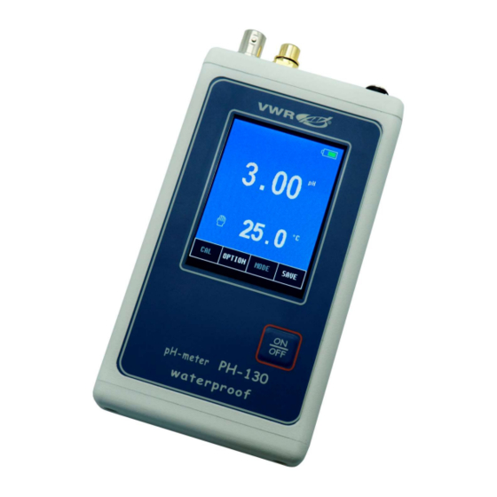
- 3 - THE OUTSIDE VIEW On the front wall of the meter there is a graphic LCD placed (Pic. 1), which displays the following readings: - pH measurement or mV measurement in mV units; - temperature measurement. At the top of the LCD the current time and date are displayed. Choosing particular functions is described in the chapter 17.1. - Page 8 In the upper wall of the meter connectors are placed with the symbols given below: BNC-50 input for connecting the combination pH or redox electrode; Chinch (RCA) input to connect the temperature probe; input for connecting the power adapter. Pic. 2. VWR Collection PH-130 pH-meter instruction manual v1.0x...
-
Page 9: The Meter's Maintenance
- 5 - THE METER‘S MAINTENANCE The meter is equipped with a graphic touchscreen. The maintenance consists in pressing particular keys and windows which appear on the screen. Grey captions in the windows and keys inform that these elements are not active in this particular operating mode. Particular keys, connected with the measurement function (i.e. -
Page 10: Switching The Meter On And Off
(description in the chapter 17.3). This function is deactivated during calibration, while memorising results or when work with the power adapter. VWR Collection PH-130 pH-meter instruction manual v1.0x... -
Page 11: Choosing The Measurement Function
- 7 - 6.1. Choosing the measurement function The user may choose the function (pH measurement or redox potential measurement in mV) to be displayed on measurement screen. To choose, on the measurement screen press the button, the options screen will display with the tab open containing the previously set FUNCTIONS configuration (Pic. -
Page 12: Stabilised Reading
- the stabilised reading signalised with changing the frame colour from white to green (only for reading marked with a frame); - the stabilised reading signalised by colour change and a sound. Return to the measurement screen by pressing the button. VWR Collection PH-130 pH-meter instruction manual v1.0x... -
Page 13: Preparation To Work
- 9 - PREPARATION TO WORK Before starting measurements: - connect prepared combination pH electrode or redox electrode to the F (BNC-50) input; - connect the temperature probe to the t (Chinch/RCA) temperature input; - if work with power adapter is planned, connect it to the P input; - switch the meter on by pressing the button. -
Page 14: Ph Measurement
- 10 - II. pH MEASUREMENT VWR Collection PH-130 pH-meter instruction manual v1.0x... -
Page 15: Preparation Of The Ph Electrode
- 11 - PREPARATION OF THE pH ELECTRODE The electrode should be prepared to work according to the manufacturer’s instructions. It is crucial to keep the electrode’s membrane clean, wash it accurately with distilled water after each measurement and gently dry with tissue paper. -
Page 16: Calibration
In case of measurements in acids calibration in 2 buffer solutions: 4.00 and 7.00 pH is recommended, in case of alkali measurements calibration in 7.00 and 10.00 pH buffers is advisable. In PH-130 the electrode characteristic is approximated linearly between the calibration points. Entering... -
Page 17: Calibration In Buffer Solutions
- 13 - 10.1. Calibration in buffer solutions When the electrode is prepared for the measurement, start the calibration in the buffer solutions. The buffers may be applied randomly. To start calibration: - connect the pH electrode and temperature probe to the F and t connector respectively (Pic. -
Page 18: Calibration With Manual Temperature Compensation
In order to enter the temperature value, press the window and in the open screen press the window, the numerical keyboard will MANUAL TEMP. appear to enter the value and confirm with the button. VWR Collection PH-130 pH-meter instruction manual v1.0x... -
Page 19: Checking The Electrode Condition
- 15 - CHECKING THE ELECTRODE CONDITION After pH electrode calibration the meter calculates its parameters: offset in pH units and slope defined as efficiency in percents. The electrode offset may be defined in pH or mV units. An ideal electrode immersed in the 7.00 pH buffer before calibration should indicate 7.00 pH which equals 0.00 mV. -
Page 20: Ph Measurement
Accurate laboratory measurements require using of a magnetic stirrer. NOTE: exceeding the measurement range is signalised with red colour of the displayed pH value; exceeding the temperature compensation range – with yellow colour. VWR Collection PH-130 pH-meter instruction manual v1.0x... -
Page 21: Measurement With Manual Temperature Compensation
- 17 - 12.2. Measurement with manual temperature compensation Disconnecting the temperature probe from the meter switches the meter to the manual temperature compensation mode. Next to the entered (not measured) temperature value, instead of the symbol, the symbol displays (Pic. 7). The procedure of measurement with manual temperature compensation is similar to that of measurement with ATC. -
Page 22: Redox Potential And Temperature Measurement
- 18 - III. REDOX POTENTIAL AND TEMPERATURE MEASUREMENT VWR Collection PH-130 pH-meter instruction manual v1.0x... -
Page 23: Setting The Redox Potential Parameters
- 19 - SETTING THE REDOX POTENTIAL PARAMETERS The redox potential parameters window is entered by selecting the redox potetial reading (a frame will be displayed around it – Pic. 8A) and the button. The screen (Pic. 8B) enables choosing the reference temperature and setting the zero offset for the relative measurement. -
Page 24: Reference Voltage
6.1; - enter the measurement parameters according to the point 13; - return to the measurement screen by pressing the button and check the reading (Pic. 9). Pic. 9. VWR Collection PH-130 pH-meter instruction manual v1.0x... -
Page 25: Setting The Temperature Measurement Parameters
- 21 - SETTING THE TEMPERATURE MEASUREMENT PARAMETERS The temperature measurement parameters window is entered by selecting the temperature reading with a frame (Pic. 10A) and next pressing the button (Pic. 10B). The screen enables choosing unit and entering the manual temperature compensation value. -
Page 26: Temperature Measurement
Instead of the measured temperature value, the value inserted by the user is displayed. Displaying of -50°C value in red while making measurement at positive temperature informs about short circuit in the temperature probe. VWR Collection PH-130 pH-meter instruction manual v1.0x... -
Page 27: Options
- 23 - IV. OPTIONS... -
Page 28: Options Screen
6.1. FUNCT. 17.2. Memory For the description of the tab, see the chapter 18. MEM. 17.3. Miscellaneous On this screen (Pic. 12A) the following parameters may be entered: Pic. 12 VWR Collection PH-130 pH-meter instruction manual v1.0x... - Page 29 - 25 - LANGUAGE choosing the language: English, German, French, Italian, Spanish, Portugese; SOUND turning the buttons sound on / off; BRIGHTNESS setting the display‘s brightness; AUTO OFF the time of non-use until the meter turns off; TIME SETUP after pressing the window the screen will TIME SETUP appear (Pic.
-
Page 30: Info
26 h brightness 17.4. Info The INFO tab contains the software version, the serial number and the factory calibration date (Pic. 13). Pic. 13. Return to the measurement mode by pressing the button. VWR Collection PH-130 pH-meter instruction manual v1.0x... -
Page 31: Memorising Readings, Memory Readout
- 27 - MEMORISING READINGS, MEMORY READOUT The meter enables recording readings of the displayed measurement functions. The readings are stored in memory even in case of power shortage. 18.1. Entering readings into the memory Each press of the button memorises the rading. The information about the free and used memory capacity will display for a short time above the reading (Pic. -
Page 32: Viewing And Deleting Readings
(Pic. 15A) press and hold the button until in the line above the button the following information will display: USED: 0 FREE: 200. Return from the viewing mode by pressing the button. VWR Collection PH-130 pH-meter instruction manual v1.0x... -
Page 33: Power, Replacing The Rechargeable Batteries
- 29 - POWER, REPLACING THE RECHARGEABLE BATTERIES The meter is powered by two R6 (AA) rechargeable batteries or by power adapter with stabilised 5V voltage, which has to be conneccted to the P connector (Pic. 2). The batteries are necessary in order to keep the clock working. -
Page 34: Technical Data
** Accuracy given for the meter. The final accuracy depends on the type of Pt-1000 probe. Temperature probe: Pt-1000 platinum resistor The probe‘s accuracy in range 0 ÷ 100 °C: for Pt1000B resistor ±0.8 °C for Pt1000A resistor ±0.35 °C VWR Collection PH-130 pH-meter instruction manual v1.0x... -
Page 35: Ordering Information
- 31 - OTHER: MEMORY CAPACITY: 200 results OPERATING TEMPERATURE: -5 ÷ 45 °C POWER SUPPLY: AA NiMH rechargeable battery x 2 5V/1000mA power adapter POWER CONSUMPTION: 0% brightness 70 mW 100% brightness 180 mW recharging batteries max. 2.4 W DISPLAY: LCD 2.8‘‘... -
Page 36: Technical Service
The customer is responsible for applying for and obtaining the necessary regulatory approvals or other authorisations necessary to run or use the Product in its local environment. VWR will not be held liable for any related omission or for not obtaining the required approval or authorisation, unless any refusal is due to a defect of the product. -
Page 37: Equipment Disposal
- 33 - EQUIPMENT DISPOSAL This equipment is marked with the crossed out wheeled bin symbol to indicate that this equipment must not be disposed of with unsorted waste. Instead it's your responsibility to correctly dispose of your equipment at lifecycle -end by handling it over to an authorized facility for separate collection and recycling. - Page 38 VWR International GmbH Brynsalleen 4 Hilpertstraße 20a 0667 Oslo D - 64295 Darmstadt Tel.: +47 22 90 00 00 Freecall: 0800 702 00 07 Email: info.no@vwr.com Tel.: +49 (0) 6151 3972 0 (international) Email: info.de@vwr.com VWR Collection PH-130 pH-meter instruction manual v1.0x...
Need help?
Do you have a question about the PH-130 and is the answer not in the manual?
Questions and answers