Table of Contents
Advertisement
Advertisement
Table of Contents

Related Manuals for Projecta IntelliJay PM300-BTJ


Summary of Contents for Projecta IntelliJay PM300-BTJ
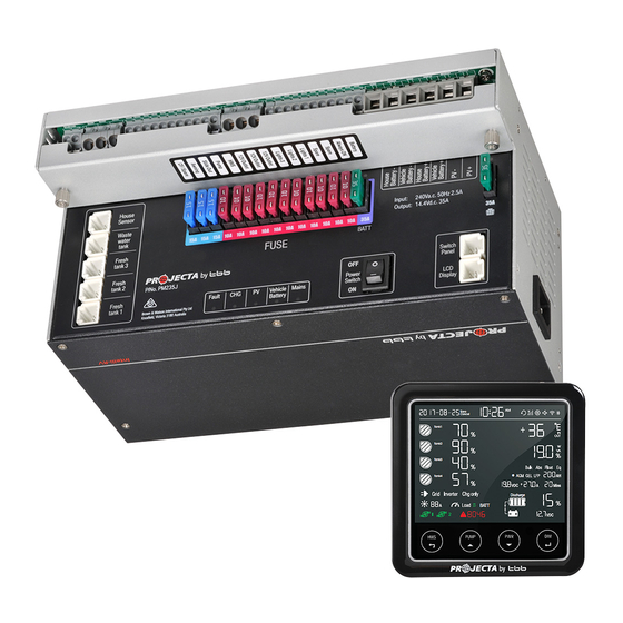
- Page 1 INTELLI ® 12V POWER MANAGEMENT SYSTEM (MPPT) PM335J Transformer Unit Phone App PMBTJ-02 Bluetooth Node PMLCD-BTJ LCD Screen (PM335J-NODE system only) (PM300-BTJ system only) P/No. PM300-BTJ & PM335J-NODE Need technical help? Contact Projecta on 1800 294 294...
- Page 2 IMPORTANT SAFETY INFORMATION Please read this manual thoroughly before use and store in a safe place for future reference. WARNINGS • Explosive gases. Prevent flames and sparks. Provide adequate ventilation during charging • Before charging, read the instructions • For indoor use. Do not expose to rain •...
-
Page 3: Table Of Contents
CONTENTS 1. INTRODUCTION 1.1 Features 1.2 LCD monitor (PM300-BTJ only) 1.3 Water tank probes 2. KEY FEATURES AND FUNCTIONS 2.1 Multiple inputs 2.2 Battery charger of stationery/house battery 2.3 Power supply mode 2.4 MPPT solar charger controller 2.5 Voltage charging relay (VCR) 2.6 Categorised outputs 2.7 Battery low voltage protection 2.8 Manual battery switch... -
Page 4: Introduction
1. INTRODUCTION PM300-BTJ and PM335J-NODE are power management systems designed for use in caravans or motor homes. These systems allow for easy installation and a user-friendly interface. Both PM300-BTJ and PM335J-NODE systems come with the same PM335J transformer unit, which the circuits in the caravan or motor home are centrally wired to. -
Page 5: Features
1.1 Features (PM300-BTJ and PM335J-NODE) • Smart battery charger 12V 35A (30A for charging current) • Multi stage adaptive charging algorithm • Active Power Factor Correction (PFC) charging • Temperature compensation charging • Voltage compensation charging • Solar charge controller (MPPT), 30A •... -
Page 6: Lcd Monitor (Pm300-Btj Only)
1.2 LCD Monitor PMLCD-BTJ (PM300-BTJ only) The LCD monitor is a digital control center for the PM335J transformer unit. See section 5.2 for operation of LCD monitor. FEATURES: • T-Bus design (can be connected to multiple devices) • System monitoring •... -
Page 7: Power Supply Mode
NOTE: If your vehicle is fitted with a smart alternator, the VCR charge system (Variable Voltage or Temperature Compensating), the VCR charge system may not function correctly and a Projecta IDC25 charging system is recommended. Please contact Projecta for further information. -
Page 8: Categorised Outputs
2.6 Categorised Outputs The 14 outputs are categorised into groups and controls as per below: OUTPUTS DESCRIPTION POSSIBLE LOAD SUITABLE Relay controlled output with fuse, protected by Awning, Slide Out, Hot Water System main master switch relay (HWS), Pump Fused outputs, protected by master switch relay Lights, ventilation fan, TV etc. -
Page 9: Structure And Installation
3. STRUCTURE AND INSTALLATION 3.1 PM300-BTJ and PM335J-NODE Power Management Systems 22 21 20 1918 16 15 14 13 12 11 10 Figure 8 Front panel of PM335J Transformer Unit LABEL DEFINITION DESCRIPTION AC Mains AC input port Computer/IEC style plug socket Temp Sensor Comm port Temperature Sensor input... -
Page 10: Lcd Monitor (Pm300-Btj Only)
128 55 Figure 9 Dimension of PM335J (Unit: mm) Installation: PM335J can be installed on a horizontal surface or vertically on a wall. Please see following instructions: Ensure clearance on both sides of PM335J unit upon installation. A recommended clearance of 5cm on each side. -
Page 11: Water Tank Probes
Figure 12 Installation of Monitor PMLCD-BTJ (Unit:mm) 3.3 Water Tank Probes 3.3.1 PMWS400 Water Tank Probe Installation Figure 13 Dimension of PMWS400 (Unit:mm) Figure 14 Installation of PMWS400 3.3.2 PMWS200 Water Tank Probe Installation Figure 15 Dimension of PMWS200 (Unit:mm) Figure 16 Installation of PMWS200... -
Page 12: Wiring
4. WIRING 4.1 Material CODE NAME MODEL/ P/No. ON LENGTH DRAWING Transformer Unit PM335J LCD Monitor PMLCD-BTJ Monitor Fresh water tank 1 level sensor Not included and to be Fresh water tank 1 level sensor ordered PMLCDC Tap water tank level sensor separately Waste water tank level sensor Solar... -
Page 13: System Schematic
4.2 System Schematic PMWS200/ PMWS200/ PMWS400 PMWS400 PMWS200/ Outdoor Battery Temperature PMWS400 PMWS200/ Temperature Sensor Sensor and Terminal PMWS400 Voltage PMTS PMBS Fresh Water Fresh Water Tap Water Waste Water Tank 1 Tank 2 Tank Tank Level Sensor Level Sensor Level Sensor Level Sensor •... -
Page 14: Preparation
4.3 Preparation PM300-BTJ and PM335J-NODE systems are designed with the concept of ‘Plug in and Play’ in mind. To complete the easy installation, a screw driver and DC cables are required. Follow Table 5 recommendation for minimum wiring size. CURRENT MINIMUM CABLE SIZE When running cables, if they pass through panels or wall, ensure the 0–5A... -
Page 15: Display
5. DISPLAY 5.1 PM335J Transformer Unit P/No. PM335 Figure 22 An overview of PM335J COLOUR STATUS DESCRIPTION Mains GREEN AC input OK AC disconnected Quick flashing (flash twice every second) AC input abnormal Vehicle Bat GREEN Alternator charging the house battery Slow flashing (flash once every second) Vehicle battery is >13.4V and is being charged by the AC... -
Page 16: Lcd Monitor (Pm300-Btj Only)
5.2 LCD Monitor (PM300-BTJ only) Time Date Bluetooth Water tank 1 Temperature Water tank 2 Output power Water tank 3 Charging state Water tank 4 House Battery:Type/Capacity Power Source House Battery: Voltage/Current/Time to go Solar charge House Battery SOC (State of Charge) Water pump Voltage of vehicle battery Alarm error code... -
Page 17: Switch Explanation
5.2.2 LCD Monitor Switch Explanation SWITCH FUNCTION DESCRIPTION To switch on/off Hot Water Service HWS on: HWS off (Appears in top left of screen for 10 seconds) PUMP To switch on/off pump Refer Figure 24 To switch off all the loads connected on DC charger Refer Figure 25 To adjust the brightness and switch off the Total three levels of brightness backlight of he monitor... -
Page 18: Operation
6. OPERATION 6.1 Configuration on PM335J Configuration of the battery type and capacity can be done through the LCD Monitor or the smart device app. 6.1.1 Load Remote Isolation Switch This function allows for the use of a remote ISO switch to turn ON/OFF the L2-L14 outputs. 6.2 Configuration on LCD Monitor Access to the configuration menu is safeguarded with a passcode. -
Page 19: Lcd Monitor Configuration Menu
6.2.1 LCD Monitor Configuration Menu Set clock Set year Battery menu Set month Pumps enable or disable Set date Factory reset Set 12-hour or 24-hour Check firmware version Set hour Enable to updating firmware Set minute Figure 27 Date and Time setting Figure 26 Main menu of setting Select AGM battery Select GEL battery... -
Page 20: Connecting To A Smart Device (Bluetooth)
6.3 Connecting to a Smart Device (Bluetooth) 1. Go to your smart device’s App Store (iPhone/iPad) or Play Store (Android) and search for the Jayco “IntelliJay PM200 & 300BTJ” app. Download this app to your smart device. 2. Ensure Bluetooth is enabled on your smart device and that permission is granted for the app to use Bluetooth and discover new connections. -
Page 21: Maintenance
6.5 MAINTENANCE 6.5.1 Battery SOC Monitoring The PM335J transformer unit features built-in state of charge (SOC) monitoring for the house battery. To ensure accurate display of this information on the LCD monitor and in the app, the following conditions must be adhered to: 1. -
Page 22: Specification
8. SPECIFICATION MODEL PM335J MODEL PM335J ELECTRICAL SPECIFICATIONS ELECTRICAL SPECIFICATIONS Mains Nominal input voltage 240±10%VAC Battery Disconnect voltage AGM/GEL/WET 10.5VDC 50/60Hz Disconnect (default) (LVD) Power factor 0.95 LFP (LiFePO 11.2 VDC (Default) Input current at full 2.5A load Delay off time 60 sec Battery Vehicle battery... - Page 23 Notes...
- Page 24 WARRANTY STATEMENT Applicable only to product sold in Australia Brown & Watson International Pty Ltd of 1500 Ferntree Gully Road, Knoxfield, Vic.,telephone (03) 9730 6000, fax (03) 9730 6050, warrants that all products described in its current catalogue (save and except for all bulbs and lenses whether made of glass or some other substance) will under normal use and service be free of failures in material and workmanship for a period of three (3) years (unless this period has been extended as indicated elsewhere) from the date of the original purchase by the consumer as marked on the invoice.
Need help?
Do you have a question about the IntelliJay PM300-BTJ and is the answer not in the manual?
Questions and answers