Advertisement
Quick Links
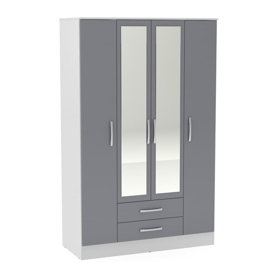
ASSEMBLY INSTRUCTIONS
4 DOOR 2 DRAWER ROBE
IMPORTANT: READ THESE INSTRUCTIONS CAREFULLY BEFORE ATTEMPTING TO ASSEMBLE OR USE YOUR 4
DOOR 2 DRAWER ROBE
PLEASE KEEP THESE INSTRUCTIONS FOR FUTURE REFERENCE
HEALTH & SAFETY:
DO NOT use this item if any parts are missing, damaged or worn.
DO NOT use this item unless all fixings are secured.
Please keep small parts out of reach of children.
Always use on a level, even surface.
CARE & MAINTENANCE:
Assemble in the room of use.
Assembly should be carried out with this item laying flat, not standing upright
Assemble on a soft, clean surface to prevent damages
To remove the printed numbers on the pieces, use a moistened cloth
Periodically check all screws & fixings to ensure they are secure.
DO NOT push the bed frame as this will damage the legs.
Always lift the bed with two people to reposition.
Keep any sharp objects away from the frame.
Page 1 of 12
Advertisement

Related Manuals for Birlea Lynx 4 Door 2 Drawer Robe


Summary of Contents for Birlea Lynx 4 Door 2 Drawer Robe
- Page 1 ASSEMBLY INSTRUCTIONS 4 DOOR 2 DRAWER ROBE IMPORTANT: READ THESE INSTRUCTIONS CAREFULLY BEFORE ATTEMPTING TO ASSEMBLE OR USE YOUR 4 DOOR 2 DRAWER ROBE PLEASE KEEP THESE INSTRUCTIONS FOR FUTURE REFERENCE HEALTH & SAFETY: DO NOT use this item if any parts are missing, damaged or worn. DO NOT use this item unless all fixings are secured.
- Page 2 Page 2 of 12...
- Page 3 Parts List Hardware List (found in box 2) Part Description Part Description Top Panel 8 x 30 mm Wooden Dowel Shelf Simple Minifix Screw Base Panel Cam Lock Left Panel Plastic Cap Right Shelf Divider 8 x 50 mm Wooden Dowel Left Shelf Divider 3.5 x 25 mm Screw Drawer Cabinet Right...
- Page 4 Step 1: Prepare the parts for assembly using hardware parts A, B, E, G, H, I, J, K, L, M, N, O, R and T. You will need to use a small mallet and a screwdriver (not provided). DO NOT use any power tools as this may damage the frame and will invalidate any claim. Page 4 of 12...
- Page 5 Step 2: Attach the drawer cabinet right panel (7) and drawer cabinet left panel (13) to the base panel (3) using hardware part S and a screwdriver (not provided). DO NOT use any power tools as this may damage the frame and will invalidate any claim. Step 3: Attach the plinths (22) to the base panel (3) using hardware parts H and T with a screwdriver (not provided).
- Page 6 Step 4: Attach the drawer cabinet top panel (14) using hardware parts C and P with a screwdriver (not provided). DO NOT use any power tools as this may damage the frame and will invalidate any claim. Step 5: Attach the supports using hardware parts C and D with a screwdriver (not provided). DO NOT use any power tools as this may damage the frame and will invalidate any claim.
- Page 7 Step 6: Attach the right panel (8) and shelf (2) using hardware parts C and D and a screwdriver (not provided). DO NOT use any power tools as this may damage the frame and will invalidate any claim. Page 7 of 12...
- Page 8 Step 7: Secure the shelf (2) to the supports using hardware parts C, D and P. Position the hanging rail (24). Attach the left panel (4) using hardware parts C and D. You will need to use a screwdriver (not provided). DO NOT use any power tools as this may damage the frame and will invalidate any claim.
- Page 9 Step 8: Attach the shelf dividers using hardware parts C and D with a screwdriver (not provided). Connect two back panels (23) together with the spine (25) and position. DO NOT use any power tools as this may damage the frame and will invalidate any claim. Page 9 of 12...
- Page 10 Step 9: Attach the top panel (1) using hardware parts C and D with a screwdriver (not provided). Secure the back panels (23) using hardware parts I, Q, V and U with a small mallet and screwdriver (not provided). DO NOT use any power tools as this may damage the frame and will invalidate any claim. Page 10 of 12...
- Page 11 Step 10: Attach the doors as shown, then attach the handles (26) using hardware part F. You will need to use a screwdriver (not provided). DO NOT use any power tools as this may damage the frame and will invalidate any claim. Page 11 of 12...
-
Page 12: Additional Information
Step 11: Assemble the drawer components using hardware parts C, D, F, M, R and S with a screwdriver (not provided). DO NOT use any power tools as this may damage the frame and will invalidate any claim. Additional Information: Page 12 of 12...
Need help?
Do you have a question about the Lynx 4 Door 2 Drawer Robe and is the answer not in the manual?
Questions and answers