
Related Manuals for PairGain T1L2BZ0A


Summary of Contents for PairGain T1L2BZ0A
- Page 1 Model List Number Part Number CLEI Code HLU-231 150-1111-84 T1L2BZ0A ECHNOLOGIES NGINEERING ERVICES ECHNICAL RACTICE 150-231-184-05...
- Page 2 Information furnished by PairGain Technologies is believed to be accurate and reliable. However, no responsibility is assumed by PairGain Technologies for its use, nor for any infringement of patents or other rights of third parties which may result from its use.
- Page 3 Check the packing list to ensure complete and accurate shipment of each listed item. If the shipment is short or irregular, contact PairGain as described in the Warranty located inside the back cover. If you must store the equipment for a prolonged period, store the equipment in its original container.
- Page 4 Inspecting the Shipment 150-231-184-05, Revision 05 October 25, 1999 HLU-231 List 8D...
-
Page 5: Table Of Contents
150-231-184-05, Revision 05 Table of Contents ABLE OF ONTENTS Overview ____________________________________________________________________________ 1 Features ..............................1 Product Enhancements ......................1 Standard Features ........................2 Compatibility .............................2 Applications ............................2 HiGain Doubler Applications ....................3 Personal Communications System Applications ..............3 Front Panel __________________________________________________________________________ 4 Installation___________________________________________________________________________ 8 Verification ............................9 Verification without a Downstream Device ................9 Verification with a Downstream Device ................9 Provisioning Requirements ......................10... - Page 6 Table of Contents 150-231-184-05, Revision 05 System Settings Screen ..................... 20 Equalization Option .................... 23 BPVT Option ...................... 23 BER Option ......................23 Margin Alarm Threshold Option ................ 24 HDSL Line Voltage Options ................24 Loopback Mode Screen ....................25 Loopback Menu without Doubler...............
- Page 7 150-231-184-05, Revision 05 Table of Contents Appendix A - Specifications____________________________________________________________ 49 HDSL Insertion Loss Guidelines .....................50 Power Consumption .........................50 Power Consumption without Doublers................50 Power Consumption with Doublers...................51 Maximum Power Dissipation......................53 Maximum Current Drain........................53 HLU-231 List 8D Card Connector....................54 Network Management Control Bus ...................54 Fuse Alarm ........................55 System Alarm Relay Output....................55 Craft Port............................55...
- Page 8 List of Figures 150-231-184-05, Revision 05 IST OF IGURES 1. HLU-231 List 8D Front Panel ........................4 2. Installing the HLU-231 List 8D into a Shelf ....................8 3. Maintenance Terminal Main Menu ......................14 4. System Spans ..............................15 5.
- Page 9 150-231-184-05, Revision 05 List of Tables IST OF ABLES 1. Front Panel Description............................5 2. Front Panel Display Messages..........................6 3. Navigational Keys on the Maintenance Terminal ..................13 4. Maintenance Terminal Screens ........................14 5. Span Status Fields and Descriptions.......................17 6. HDSL System Alarms ............................18 7.
- Page 10 List of Tables 150-231-184-05, Revision 05 October 25, 1999 HLU-231 List 8D...
-
Page 11: Overview
Overview VERVIEW ® ® The PairGain HiGain Line Unit HLU-231 List 8D is the Central Office (CO) side of a repeaterless T1 transmission system. When used in conjunction with a HiGain Remote Unit (HRU), the system provides 1.544 Mbps transmission on two unconditioned copper pairs over the full Carrier Service Area (CSA) range. The CSA includes loops up to 12,000 feet of 24 AWG or 9,000 feet of 26 AWG wire, including bridged taps. -
Page 12: Standard Features
Overview 150-231-184-05, Revision 05 Standard Features • Selectable DS1 pre-equalizer • Front panel features: – Four-character status display – DS1 splitting and bridge access – Status Light Emitting Diode (LED) – RS-232 craft port for connection to a maintenance terminal •... -
Page 13: Higain Doubler Applications
150-231-184-05, Revision 05 Overview HiGain Doubler Applications For applications without doublers, the HLU-231 is directly connected to the HRU by the two HDSL cable pairs. The HLU-231 List 8D is compatible with all HiGain HRUs. For doubler applications, one to four doublers can be used in the HDSL loops between the HLU and HRU. •... -
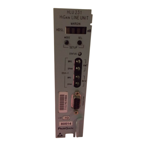
Page 14: Front Panel
Front Panel 150-231-184-05, Revision 05 RONT ANEL The HLU-231 List 8D front panel is shown in Figure 1. The front panel components are described Table 1 on page 5. For pinout diagrams of the HLU card-edge connector and the craft port, refer to “Appendix A - Specifications”... - Page 15 150-231-184-05, Revision 05 Front Panel Table 1. Front Panel Description Front Panel Feature Function Front panel display Displays four-character status, provisioning, and alarm system messages.The front panel display illuminates when power is initially applied. To conserve power the display only remains on for 4 minutes.
-
Page 16: Front Panel Display Messages
Front Panel 150-231-184-05, Revision 05 Table 2 lists the front panel display messages. The four-character displays report the code of an alarm, loopback or diagnostic message, in some cases followed by a second four-character message that modifies the first message with a value or current configuration setting. - Page 17 150-231-184-05, Revision 05 Front Panel Table 2. Front Panel Display Messages (Cont.) Message Full Name Description DIAGNOSTIC MESSAGES 1=xx or 2=yy HDSL Loop Margin 1 or 2 Indicates the power of the received HDSL signal on each loop relative to noise. Any value of 06 or greater is adequate for reliable system operation.
-
Page 18: Installation
Upon receipt of the equipment, visually inspect the contents for signs of damage. If the equipment has been damaged in transit, immediately report the extent of damage to the transportation company and to PairGain Technologies. Figure 2. Installing the HLU-231 List 8D into a Shelf When installing an HLU in a chassis, be sure to wear an antistatic wrist strap. -
Page 19: Verification
150-231-184-05, Revision 05 Installation ERIFICATION Once the HLU-231 is installed, verify that it is operating properly by monitoring the: • Status LED • Status messages reported by the front panel display (see Table 2 on page Verification without a Downstream Device If there is no downstream device installed: Verify that the HLU powers up. -
Page 20: Provisioning Requirements
Installation 150-231-184-05, Revision 05 ROVISIONING EQUIREMENTS Refer to “Provisioning” on page 11 for information about using the MODE and SEL buttons or the Maintenance Terminal screens to configure the HLU. While the MODE and SEL buttons can be used to manually accomplish some provisioning tasks, such as setting system options, the Maintenance Terminal screens (available when you connect a PC to the craft port) can handle all provisioning tasks. -
Page 21: Provisioning
150-231-184-05, Revision 05 Provisioning ROVISIONING There are two methods for provisioning the HLU-231 List 8D: • Use the MODE and SEL buttons on the front panel of the HLU to: – Set system options – Reset the HLU to its factory default settings for system options –... -
Page 22: Resetting To Factory Default Values
Provisioning 150-231-184-05, Revision 05 Resetting to Factory Default Values All user options (Table 8 on page 21) can be set to the factory default values using the MODE and SEL buttons. To set the user options to their default values: Press the SEL button for 6 seconds until the following message appears: DFLT NO Press the SEL button while the DFLT NO message is displayed. -
Page 23: Using A Maintenance Terminal
150-231-184-05, Revision 05 Provisioning SING A AINTENANCE ERMINAL Connecting to a Maintenance Terminal The craft port on the front panel allows you to connect the HLU-231 to a maintenance terminal (ASCII terminal or PC running a terminal emulation program). Once connected to a maintenance terminal, you can access the maintenance, provisioning, performance, and troubleshooting screens. -
Page 24: Maintenance Terminal Main Menu
Provisioning 150-231-184-05, Revision 05 Maintenance Terminal Main Menu Figure 3 shows the Maintenance Terminal Main Menu from which you can access system administration screens. The function of each screen selection is listed in Table 4. To access a screen, type the letter shown next to the menu item. -
Page 25: Selecting A Maintenance Terminal Function
150-231-184-05, Revision 05 Provisioning Selecting a Maintenance Terminal Function To perform a function within the Maintenance Terminal screens, you can: • Press the key indicated to the left of the selection. • Press the letter in parenthesis for the parameter to be changed. System Spans As shown in Figure... -
Page 26: Span Status Screen Without Doublers
Provisioning 150-231-184-05, Revision 05 Span Status Screen without Doublers SPAN STATUS TIME: 10:05:11 DATE: 10/08/99 Circuit ID#: ALARMS: NONE LOOPBACK: OFF POWER LEVEL: LOW HDSL-1 HDSL-2 HDSL-1 HDSL-2 cur/min/max cur/min/max cur/min/max cur/min/max MARGIN: 21/20/22 23/22/24 21/19/22 22/21/24 dB PULSE ATTN: INS LOSS: 24 HOUR ES: 00004... -
Page 27: Span Status Fields And Descriptions
150-231-184-05, Revision 05 Provisioning Table 5 lists the Span Status fields and descriptions. Table 6 Table 7 on page 18 describe alarm and loopback messages displayed on the Span Status screens. Table 5. Span Status Fields and Descriptions Span Status Field Description Time Time of day when Span Status was checked. -
Page 28: Loopback Messages
Provisioning 150-231-184-05, Revision 05 Table 6. HDSL System Alarms Message Name Description Bit Error Rate The Total System Error Count (TSEC) has exceeded the user-selected threshold. CHREV-SPn Channels Reversed The Loop 1 and Loop 2 pairs are reversed at the HDU or HRU input ports. -
Page 29: Set Clock Screen
150-231-184-05, Revision 05 Provisioning Set Clock Screen Press at the Maintenance Terminal Main Menu to open the Set Clock screen (Figure SET CLOCK TIME: 00:14:33 DATE: 10/08/99 CIRCUIT ID#: Format: HH:MM MM/DD/YY NEW TIME: NEW DATE: (U)PDATE REMOTE? Figure 7. Set Clock Screen Time information is lost when power is removed. -
Page 30: System Settings Screen
Provisioning 150-231-184-05, Revision 05 System Settings Screen The options set from the System Settings screen are the same as the options set through the HLU-231 front panel Mode and SEL buttons (except for Margin Alarm Threshold and DS0 Blocking, which can only be set at this screen). -
Page 31: Hlu-231 List 8D System Settings
150-231-184-05, Revision 05 Provisioning Table 8 describes the System Settings options and lists the corresponding codes. Most of these options must be configured through the Maintenance Terminal System Settings screen. EQL, LBTO, LNCD, and CONF can also be set using the MODE and SEL buttons. Factory default parameters appear in boldface type. Table 8. - Page 32 Provisioning 150-231-184-05, Revision 05 Table 8. HLU-231 List 8D System Settings (Cont.) System Settings Code Parameter Description Screen Options RLOS Alarm Enables a remote DS1 LOS condition at the input to the HRU to generate an LOS alarm. AIS or LOS (depending on ALMP) is sent towards the network. Prevents a remote DS1 LOS condition at the input to the HRU from causing an LOS alarm.
-
Page 33: Equalization Option
150-231-184-05, Revision 05 Provisioning Equalization Option Equalization is the configuration of system transmission characteristics within specified limits. An adaptive equalizer inserts a frequency-shaped loss that corresponds to an equivalent addition of an appropriate cable length. By simulating the additional cable loss necessary for correct operation, the equalizer compensates for a range of variation in transmission path characteristics. -
Page 34: Margin Alarm Threshold Option
Provisioning 150-231-184-05, Revision 05 Margin Alarm Threshold Option To set the Margin Alarm Threshold: Select from the System Settings Main Menu screen. Enter the desired minimum acceptable alarm threshold from the 0 to 15 dB range. This causes a system alarm to occur if either the margin on HDSL Loop 1 (MAL1) or Loop 2 (MAL2) drops below the selected threshold value. -
Page 35: Loopback Mode Screen
150-231-184-05, Revision 05 Provisioning Loopback Mode Screen Use the Loopback Menu to issue loopbacks to the HiGain system. Depending upon the number of doublers, there can be up to five loopback screens. Press from the Maintenance Terminal Main Menu to display the Loopback Menu. Figure 9 shows an example of a Loopback Menu when no doublers are present;... -
Page 36: Loopback Menu Without Doubler
Provisioning 150-231-184-05, Revision 05 Loopback Menu without Doubler LOOPBACK MENU TIME: 00:15:34 DATE: 10/08/99 CIRCUIT ID#: A. DISABLE LOOPBACKS B. NETWORK LOOP HLU (NLOC) C. NETWORK LOOP HRU (NREM) G. CUSTOMER LOOP HLU (CREM) H. CUSTOMER LOOP HRU (CLOC) (E)xit Figure 9. -
Page 37: Initiating A Loopback
150-231-184-05, Revision 05 Provisioning Initiating a Loopback To send one of the available loopbacks, press the appropriate letter in the Loopback Menu. The following prompt appears: PLEASE WAIT....A series of dots moves from left to right indicating that the command has been issued. When this process completes, the system returns to the Maintenance Terminal Main Menu. -
Page 38: View Performance Data Screen
Provisioning 150-231-184-05, Revision 05 View Performance Data Screen The Performance Data screen shows the Errored (ES) and Unavailable Seconds (UAS) for both HDSL loops and each T1 input at 15-minute intervals over a 4-hour time interval. (The ES and UAS data is separated by a slash mark.) Earlier and later data, in 4-hour time periods on different span screens, is accessed by pressing (Previous) or (Next) respectively. -
Page 39: Performance Data Screen Without Doubler
150-231-184-05, Revision 05 Provisioning Performance Data Screen without Doubler Figure 12 shows a single non-doubler span. This screen shows the Errored and Unavailable Seconds for the HDSL span between the HLU-231 and the HRU. Date: 10/08/99 PERFORMANCE DATA CIRCUIT ID#: ERRORED SECONDS/UNAVAILABLE SECONDS HDSL-1 HDSL-2... -
Page 40: View Performance History Screen (7-Day And 31-Day)
Provisioning 150-231-184-05, Revision 05 View Performance History Screen (7-Day and 31-Day) The Performance History screen shows the daily occurrences of ES and UAS over a 7-day or 31-day period in 24-hour increments. Errored Seconds and Unavailable Seconds for both HDSL loops and each of the two DS1 inputs are listed for the current and previous period. -
Page 41: Performance History Screen For Doubler Applications (7-Day And 31-Day)
150-231-184-05, Revision 05 Provisioning Performance History Screen for Doubler Applications (7-Day and 31-Day) The Performance History screen displays information by span when doublers are present. With multiple doublers (up to four), there can be as many as five span screens. Figure 15 is an example of a 31-day screen showing data for the fifth span between HDU4 and the HRU. -
Page 42: View Alarm History Screen
Provisioning 150-231-184-05, Revision 05 View Alarm History Screen Press at the Maintenance Terminal Main Menu to open the Alarm History screen. This screen allows you to view alarms that are currently active. In the Alarm History screen (Figure 16 Figure 17 on page 33) the: •... -
Page 43: Alarm History Screen Without Doubler
150-231-184-05, Revision 05 Provisioning Alarm History Screen without Doubler ALARM HISTORY TIME: 00:01:58 DATE: 10/08/99 CIRCUIT ID#: Type First Last Current Count LOS, DS1-HLU LOS, DS1-HRU SPAN1 LOSW, HDSL1 10/08/99-00:00 10/08/99-00:00 SPAN1 LOSW, HDSL2 10/08/99-00:00 10/08/99-00:00 SPAN1 MARGIN L1 SPAN1 MARGIN L2 PWR-SHRT PWR-GND LAST CLEARED: 10/08/99-00:01... -
Page 44: System Inventory Screen
Provisioning 150-231-184-05, Revision 05 System Inventory Screen The System Inventory screen (Figure 18 on page 35) lists the six possible units that can comprise one HiGain circuit: one HLU, one HRU and up to four doublers. The information in the System Inventory Screen is presented as follows: •... -
Page 45: System Inventory Screen Without Doubler
150-231-184-05, Revision 05 Provisioning System Inventory Screen without Doubler SYSTEM INVENTORY TIME: 00:27:59 DATE: 10/08/99 A. CIRCUIT ID: UNIT PRODUCT UNIT ID HLU-231 L8D V7.2 NOT REQUIRED B. HRU HRU-402 L1A V1.3 Remote Unit C. DB1 D. DB2 F. DB3 G. -
Page 46: View Troubleshooting Screen
Provisioning 150-231-184-05, Revision 05 View Troubleshooting Screen The Troubleshooting screen graphically analyzes the circuit and identifies any problem areas. Press at the Maintenance Terminal Main Menu to access the Troubleshooting screen. The Troubleshooting screen (Figure 20) appears showing the HLU, the HRU and any doublers that are in the circuit (up to four). HDSL LIne 1 TIME: 17:34:31 TROUBLESHOOTING... -
Page 47: Troubleshooting With Help
150-231-184-05, Revision 05 Provisioning To display the circuit Help diagram (Figure 22), press . The symbol legend used to describe all circuit events and the corresponding troubleshooting tips are located beneath the Help diagram. A troubleshooting symbol on the diagram identifies the location of a problem. Those legend symbols which appear in parentheses are also keyboard commands for obtaining additional information. -
Page 48: Troubleshooting With Margin Values
Provisioning 150-231-184-05, Revision 05 Press to display margin values for the circuit (Figure 23). TIME: 01:34:51 TROUBLESHOOTING with MARGIN VALUES DATE: 10/08/99 CIRCUIT ID#: >>>>| |=======| |=======| |=======| |=======| |=======| |>>>> <<<<| |=======| |=======| |=======| |=======| |=======| |<<<< |___|23 22|___|21 22|___|22 23|___|24 22|___|22... -
Page 49: Troubleshooting With Errored Seconds Values
150-231-184-05, Revision 05 Provisioning Press (in E R) to view the 24-hour DS1 and HDSL errored seconds values for the circuit (Figure 25). DATE: 09/20/99 CIRCUIT ID#: 001 | |009 002| |009 001| |005 002| |005 002| |004 009| >>>>| |=======| |=======| |=======|... -
Page 50: Troubleshooting
Troubleshooting 150-231-184-05, Revision 05 ROUBLESHOOTING This section provides information about system alarms and loopback testing. In addition to these troubleshooting aids, the Maintenance Terminal provisioning interface includes troubleshooting screens (see “View Troubleshooting Screen” on page 36) that provide a basic graphical analysis of system problems. YSTEM LARMS Table 12... -
Page 51: Alarm Option For Dlc Feed
150-231-184-05, Revision 05 Troubleshooting Alarm Option for DLC Feed To improve HiGain compatibility with the switch-to-protect features used in DLC feeder applications, the HLU-231 has an Alarm Pattern Option (ALMP) that allows you to select either an AIS or LOS T1 output payload for the following alarms: •... - Page 52 Troubleshooting 150-231-184-05, Revision 05 Table 13. Summary of HiGain Loopback Codes Method of Transmission Loopback Code Description Test Set Craft Port MODE/SEL 11000. . . NI LPBK 2-in-5 SMJK LpUp 11000 SmartJack Loopup or NID payload (PL) code. Invokes HRU loopback towards network. (PL) 2-in-5 SMJK LpUp...
-
Page 53: A5Lb Loopback Commands
150-231-184-05, Revision 05 Troubleshooting A5LB Loopback Commands A5LB is a specific, addressable, repeater loopback mode which is supported by the HLU-231 List 8D. This loopback mode provides the HiGain system with sophisticated maintenance and troubleshooting tools. The A5LB is patterned after the Teltrend Mod 1 addressable T1 repeater loopbacks and has been enhanced to handle the specific requirements of the following HiGain customers: •... -
Page 54: Initiating A Manual Loopback Session
Troubleshooting 150-231-184-05, Revision 05 Initiating a Manual Loopback Session With the exception of SmartJack, any of the HiGain loopbacks can be executed using the MODE and SEL buttons. When executing a manual loopback session using the MODE and SEL buttons: •... -
Page 55: Loopback Test Procedures
150-231-184-05, Revision 05 Troubleshooting OOPBACK ROCEDURES The following sections provide step-by-step test procedures for verifying the integrity of the HDSL channels at every module location as well as the DS1 channels to the customer and the local DSX-1 interface. General Troubleshooting Tips If trouble is encountered on the DSX-1 interface of the HLU-231 List 8D, verify that the: •... -
Page 56: A5Lb Test Procedures
Troubleshooting 150-231-184-05, Revision 05 A5LB Test Procedures Using the codes listed in Table 14, a network tester can activate NLOC, NDU or NREM loopbacks (or SMJK, if enabled). A tester at the customer premises can activate CLOC, CDU or CREM loopbacks. All loopbacks shown Table 14 can also be initiated from the HLU-231 front panel MODE and SEL buttons (see “Setting Options... - Page 57 150-231-184-05, Revision 05 Troubleshooting To perform the A5LB test procedures: Send the inband Arming and NI LPBK code 11000 to the HLU-231 for at least 5 seconds. Monitor the output of the HLU-231 for the return of the pattern. Return of the pattern indicates one of the following: The HRU has looped up (if the SMJK Loopback option is Enabled).
- Page 58 Troubleshooting 150-231-184-05, Revision 05 The Armed mode has an automatic time-out of 120 minutes but this timer is reset to 120 for any of the following events: • Loopback terminates (manually or time-out) • Query • Alternate query • Far end activate •...
-
Page 59: Appendix A - Specifications
150-231-184-05, Revision 05 Appendix A - Specifications A - S PPENDIX PECIFICATIONS This appendix provides general specifications, pinout diagrams for the craft port and card-edge connector, HDSL insertion loss guidelines, and power consumption and dissipation tables. HDSL Line Code 784 kbps 2B1Q HDSL Output +13.5 dBm ±0.5 dB at 135 HDSL Line Impedance... -
Page 60: Hdsl Insertion Loss Guidelines
19/0.91 1.54 (a) At 196 kHz, 68°F (20°C) A Windows-based program, Cable Calculator, may be downloaded from the Customer Site portion of PairGain’s web site at www.pairgain.com. If you don’t have a customer password, contact your sales representative. OWER ONSUMPTION The maximum power consumption and heat dissipation depends upon the type of remote and doubler units in the system and the CPE power setting. -
Page 61: Power Consumption With Doublers
150-231-184-05, Revision 05 Appendix A - Specifications Power Consumption with Doublers Table 17 through Table 23 list the power consumed and dissipated by the HLU-231 List 8D when it is used with any of the four basic doubler types in the HiGain family. The maximum current drawn by the CO supply is also listed. -
Page 62: Power Parameters-Two Doublers (Hdu-451 List 3, 4, 3B Or 4B)
Appendix A - Specifications 150-231-184-05, Revision 05 Table 20 through Table 22 show power parameters for two doubler, line-powered circuits on 9 kft, 26 AWG loops. Table 20. Power Parameters—Two Doublers (HDU-451 List 3, 4, 3B or 4B) HRU CPE 42.5 V Power HRU Model No. -
Page 63: Maximum Power Dissipation
150-231-184-05, Revision 05 Appendix A - Specifications AXIMUM OWER ISSIPATION The Maximum Power Dissipation measures the power that is converted into heat that builds up within the unit. It contributes to the total heat generated in the space around the unit. It is used to determine the maximum number of fully loaded shelves per bay that does not exceed the maximum allowable power dissipation density in watts per square foot to comply with GR-63. -
Page 64: Hlu-231 List 8D Card Connector
The HLU-231 List 8D provides a Network Management Control Bus on pin 46 of the card-edge connector. This allows the various PairGain Management System protocols to manage the HLU through the HMU-319 HiGain Management Unit. When the HLU-231 is under management, the MNGD message displays periodically on the HLU-231 List 8D front panel display. -
Page 65: Fuse Alarm
150-231-184-05, Revision 05 Appendix A - Specifications Fuse Alarm Pin 32 on the card-edge connector is a Fuse Alarm that is driven to -48 V through a 1000 resistor when the onboard fuse opens. System Alarm Relay Output The normally open alarm contacts available across pins 20 and 21 (Figure 29 on page 54) comprise the HLU-231 List 8D system alarm output. -
Page 66: Appendix B - Functional Operation
UNCTIONAL PERATION PairGain HDSL technology provides full-duplex services at standard T1 rates over copper wires between an HLU and an HRU, which comprise one HiGain system. HiGain systems use PairGain 2-Binary 1-Quartenary (2B1Q) HDSL transceiver systems to establish two, full-duplex, 784 kbps data channels between the HLU-231 and a remotely located HDU or HRU. -
Page 67: Ground Fault Detect
150-231-184-05, Revision 05 Appendix B - Functional Operation ROUND AULT ETECT The HLU-231 has a Ground Fault Detect (GFD) circuit which detects a ground or a resistive path to ground on any wire of any loop of any span with a non-zero voltage. For low voltage applications (-140 V), this circuit is active during start-up by applying the bipolar voltage to the loops. -
Page 68: Appendix C - Compatibility
EPEATER HELVES AND ELATED QUIPMENT The HLU-231 List 8D is compatible with the following T1 repeater shelves and associated equipment: • PairGain HCS-417 (23 inch) • PairGain HCS-418 (19 inch) • PairGain HCS-402 (2-slot) • AT&T 220 Office Repeater Bay (ORB) •... - Page 69 150-231-184-05, Revision 05 Appendix C - Compatibility Table 24. HiGain Doubler Deployment Matrix Maximum Number of Doublers Per Circuit HDU-451, List 3, 3B, 4, 4B HDU-437, 439 HDU-404, 407, 409 Line Powered Local Powered Line Powered Local Powered Line Powered Local Powered HLU Model HLU-231 Lists 3D/6D;...
-
Page 70: Appendixd - Product Support
PairGain Customer Service Group provides expert pre-sales and post-sales support and training for all its products. ECHNICAL UPPORT Technical assistance is available 24 hours a day, 7 days a week by contacting PairGain Customer Service Group at: 800.638.0031 or 714.832.9922 Telephone: The 800 telephone support line is toll-free in the U.S. -
Page 71: Returns
Fax: 714.832.9923 Email Address: rma@pairgain.com Include the following information, in writing, along with the equipment you are returning: Company name, address, the name of a person PairGain can contact regarding this equipment, and a phone number. The original purchase order number. -
Page 72: Appendix E - Glossary
Appendix E - Glossary 150-231-184-05, Revision 05 E - G PPENDIX LOSSARY 2B1Q 2 Binary,1 Quaternary HCDS High Capacity Digital Service Alarm Cut Off HiGain Central Office Shelf Alarm Indication Signal, indicating HDSL High-bit-rate Digital Subscriber Line transmission of an all ones pattern ALMP Alarm Pattern HiGain Doubler Unit... - Page 73 150-231-184-05, Revision 05 Appendix E - Glossary RLOS Remote Loss of Signal Return Material Authorization SAIS SmartJack AIS Super Frame SMJK SmartJack Total Error Count TSEC Total System Error Count Unavailable Seconds Transmit HLU-231 List 8D October 25, 1999...
-
Page 75: Certification And Warranty
Do not try to repair the unit. If it fails, replace it with another unit and return the faulty unit to PairGain for repair. Any modifications of the unit by anyone other than an authorized PairGain representative voids the warranty. - Page 76 Corporate Office 14402 Franklin Avenue Tustin, CA 92780 Tel: 714.832.9922 Fax: 714.832.9924 For Technical Assistance: 800.638.0031...
Need help?
Do you have a question about the T1L2BZ0A and is the answer not in the manual?
Questions and answers