PairGain HIGAIN HLU-388 Manual
Hide thumbs
Also See for HIGAIN HLU-388:
- Quick installation manual (36 pages) ,
- Manual (80 pages) ,
- Quick installation manual (20 pages)
Table of Contents
Advertisement
Quick Links
Advertisement
Table of Contents

Subscribe to Our Youtube Channel
Related Manuals for PairGain HIGAIN HLU-388


Summary of Contents for PairGain HIGAIN HLU-388
- Page 1 Model List Number Part Number CLEI Code HLU-388 150-1141-25 T1L2BBYAAA HLU 388 I AIN (dB) SETUP MODE SEL STATUS ECHNOLOGIES NGINEERING ERVICES ECHNICAL RACTICE ™150-388-125-01v¨ 150-388-125-01 ECTION...
- Page 2 PairGain and HiGain are registered trademarks of PairGain Technologies, Inc. Information contained in this document is company private to PairGain Technologies, Inc., and shall not be modified, used, copied, reproduced or disclosed in whole or in part without the written consent of PairGain.
- Page 3 Check the packing list to ensure complete and accurate shipment of each listed item. If the shipment is short or irregular, contact PairGain as described in the Warranty. If you must store the equipment for a prolonged period, store the equipment in its original container.
- Page 4 Inspecting Shipment 150-388-125-01, Revision 01 September 15, 1998 HLU-388 List 2E...
-
Page 5: Table Of Contents
150-388-125-01, Revision 01 Table of Contents ABLE OF ONTENTS Overview ____________________________________________________________________________ 1 Features ..............................1 Applications ............................2 Applications Without HiGain Doublers ................2 Applications With HiGain Doublers ...................2 Product Description ___________________________________________________________________ 3 Front Panel ............................3 Status LED...........................4 Front Panel Display ......................4 Card Connector ..........................7 Network Management Control Bus ..................7 Fuse Alarm ..........................7 Installation___________________________________________________________________________ 8... - Page 6 Table of Contents 150-388-125-01, Revision 01 System Settings ..........................20 DS0 Blocking Option......................21 DS1 Line Code Option...................... 21 Margin Alarm Threshold ....................21 HAIS Selections ........................ 22 System Settings Menu Options ....................... 23 Loopback Menu..........................25 Loopback Menu: No Doubler ................... 26 Loopback Menu: One Doubler ..................
- Page 7 150-388-125-01, Revision 01 Table of Contents Appendix C - Functional Operation _____________________________________________________ 50 HDSL Line Voltage......................51 Ground Fault Detect ......................52 Power Consumption .........................52 Power Consumption: Without Doublers................52 Maximum Power Dissipation:................52 Maximum Power Consumption: .................52 Maximum Current Drain:..................52 Power Consumption: With Doublers.................53 Appendix D - Compatibility ___________________________________________________________ 54 T1 Repeater Shelves and Related Equipment ..................54 Doubler Deployment........................54...
- Page 8 Table of Contents 150-388-125-01, Revision 01 viii September 15, 1998 HLU-388 List 2E...
- Page 9 150-388-125-01, Revision 01 List of Figures IST OF IGURES 1. HLU-388 List 2E Front Panel ........................3 2. HLU-388 List 2E Card-Edge Connector ......................7 3. Installing the HLU-388 into a Shelf ......................8 4. DB-9 RS-232 I/O Pinouts...........................11 5. System Spans..............................12 6. Maintenance Terminal Main Menu ......................13 7.
- Page 10 List of Tables 150-388-125-01, Revision 01 IST OF ABLES 1. HDSL Loss Over Cables..........................2 2. Front Panel Components and Labels ......................4 3. Status LED Descriptions..........................4 4. Front Panel Display Messages ........................5 5. Navigational Keys on the Maintenance Terminal ..................12 6.
-
Page 11: Overview
Compatible with high-density Span Terminating Shelves (STS) • Selectable loopback activation codes • RS-232 Craft port for connection to a maintenance terminal • Compatible with PairGain Management System • Front panel operator setup • Lightning and power cross protection on HDSL interfaces •... -
Page 12: Applications
Overview 150-388-125-01, Revision 01 PPLICATIONS HiGain systems provide a cost-effective, easy-to-deploy method for delivering T1 High Capacity Digital Service (HCDS) over metallic pairs. • The service is deployed over two unconditioned, non-loaded copper pairs, yet it demonstrates a quality that is competitive with fiber optics. -
Page 13: Product Description
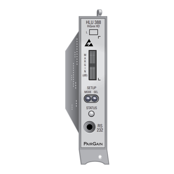
HLU-388 List number HiGain HD Front panel display CLEI/ECI bar code label (dB) System option buttons SETUP MODE SEL Status LED STATUS Craft port PAIRGAIN Configuration number Figure 1. HLU-388 List 2E Front Panel HLU-388 List 2E September 15, 1998... -
Page 14: Status Led
Product Description 150-388-125-01, Revision 01 Table 2. Front Panel Components and Labels Front Panel Feature Function List number The HLU-388 version number. Front panel display Displays four-character status, provisioning, and alarm system messages. System option buttons Permits the user options to be monitored and modified without the need of a maintenance (MODE and SEL) terminal. - Page 15 150-388-125-01, Revision 01 Product Description Table 4. Front Panel Display Messages Message Full Name Description CREM Customer Remote Loopback Signal from customer is looped back to the customer at HLU-388. NLOC Network Local Loopback DSX-1 signal is looped back to DSX-1 at HLU. CLOC Customer Local Loopback Signal from Customer is looped back to the customer at the HRU.
- Page 16 Product Description 150-388-125-01, Revision 01 Table 4. Front Panel Display Messages (Cont.) Message Full Name Description CODE Line Code: AMI, B8ZS The line code that HLU-388 is receiving at its DSX-1 interface, if the DS1 option is set to Auto. Otherwise, it mimics either of the other two DS1 line code settings, AMI or B8ZS.
-
Page 17: Card Connector
The HLU-388 provides a Network Management Control Bus on pin 104 of the card-edge connector. This allows the various PairGain Management System protocols to manage the HLU through the HMU-319 HiGain Management Unit. Whenever the HLU-388 is under management, the MNGD message displays periodically on the HLU-388 front panel display. -
Page 18: Installation
Installation 150-388-125-01, Revision 01 NSTALLATION This product contains static-sensitive components. Be sure to ground yourself properly before touching the HLU-388. To install the HLU-388: Slide the HLU-388 into the card guides for the desired slot, then push the unit back until it touches the backplane card-edge connector and the retaining latch on the front panel opens (Figure HLU-388... -
Page 19: Provisioning
150-388-125-01, Revision 01 Provisioning ROVISIONING There are two methods for provisioning the HLU-388: • Use the MODE and SEL buttons on the front panel. • Access system settings screens through the Craft port. No dip switches or jumpers are required to provision the HLU-388 as it contains a Non-Volatile RAM (NVRAM) which stores the system option settings. -
Page 20: Displaying System Inventory
Provisioning 150-388-125-01, Revision 01 Displaying System Inventory To scroll through an inventory of system parameters, press the MODE button for three or more seconds. The following parameters are displayed: • HLU software version number • HLU List number • Type of frame pattern being received from the DSX-1 •... - Page 21 150-388-125-01, Revision 01 Provisioning TERMINAL DB-9 Connector (DTE) HLU-388 DB-9 Connector (DCE) RD (Receive Data) (Female) TD (Transmit Data) TERMINAL DB-25 Connector (DTE) Figure 4. DB-9 RS-232 I/O Pinouts HLU-388 List 2E September 15, 1998...
-
Page 22: Maintenance
Maintenance 150-388-125-01, Revision 01 AINTENANCE This section explains how to navigate through the Maintenance Terminal screens and describes the Main Menu and its various options. AVIGATING THE AINTENANCE ERMINAL CREENS The following sections describe an HLU-388 system with and without doublers, how to navigate through the maintenance screens, and how to select options. -
Page 23: Selecting An Option
150-388-125-01, Revision 01 Maintenance Selecting an Option To select an option within the Maintenance Terminal screens, you can: • Press the key indicated to the left of the selection. • Press the letter in parenthesis of the parameter to be changed. An invalid entry produces the following message and identifies the name of a field where the invalid entry occurred: >... -
Page 24: View Span Status
Maintenance 150-388-125-01, Revision 01 Table 6. Maintenance Terminal Screens Screen Function See page: View Span Status Provides access to subscreens that allow you to monitor the HDSL line between the HLU and the HRU. Set Clock Allows you to set both the time and the date parameters at the HLU, and to update the same settings at the HRU. -
Page 25: Span Status Screen: No Doubler
150-388-125-01, Revision 01 Maintenance SPAN STATUS TIME: 00:14:11 DATE: 05/02/98 Circuit ID#: ALARMS: LAIS LLOS RLOS LOSW1 LOSW2 LOOPBACK: OFF HDSL-1 HDSL-2 HDSL-1 HDSL-2 cur/min/max cur/min/max cur/min/max cur/min/max MARGIN: PULSE ATTN: OFFSET: 24 HOUR ES: 00000 00000 00000 00000 seconds 24 HOUR UAS: 00607 00607... - Page 26 Maintenance 150-388-125-01, Revision 01 SPAN 2 STATUS TIME: 00:14:11 DATE: 05/02/96 Circuit ID#: ALARMS: LAIS LLOS RLOS LOSw1 LOSW2 LOOPBACK: OFF HDU-1 HDSL-1 HDSL-2 HDSL-1 HDSL-2 cur/min/max cur/min/max cur/min/max cur/min/max MARGIN: PULSE ATTN: 24 HOUR ES: 00000 00000 00000 00000 seconds 24 HOUR UAS: 00607...
-
Page 27: Span Status Fields, Alarms, And Loopbacks
150-388-125-01, Revision 01 Maintenance Span Status Fields, Alarms, and Loopbacks Table 7 lists the Span Status fields and descriptions. Table 8 on page 18 lists all possible alarms and their descriptions, and all possible loopbacks and their descriptions. Table 7. Span Status Fields and Descriptions Field Description Time... - Page 28 Maintenance 150-388-125-01, Revision 01 Table 8. HLU-388 Status Menu Messages Message Full Name Description ALARMS LLOS Local Loss of Signal No signal from HLU-388 local T1 input. RLOS Remote Loss of Signal No signal from HRU T1 input. LOSW1 LOSW2 Loss of Sync Word 1 or 2 One of the HDSL loops has lost synchronization.
-
Page 29: Set Clock
150-388-125-01, Revision 01 Maintenance LOCK Press from the Maintenance Terminal Main Menu to open the Set Clock screen (Figure 10). SET CLOCK TIME: 00:14:33 DATE: 02/02/98 CIRCUIT ID#: Format: HH:MM MM/DD/YY NEW TIME: NEW DATE: (U)PDATE REMOTE? Figure 10. Set Clock Menu All time information is lost when power is removed. -
Page 30: Update The Hru Time And Date
Maintenance 150-388-125-01, Revision 01 Update the HRU Time and Date For HRUs with software version 6.4 or higher, or HRUs List 6 or higher, the remote unit date and time is set by using this option. To update the remote, do one of the following: •... -
Page 31: Ds0 Blocking Option
150-388-125-01, Revision 01 Maintenance DS0 Blocking Option To set the DS0 Blocking option from the Main Menu: Press & to select the Systems Settings menu (see Figure 11 on page 20). Press for the DS0 blocking selection. The DS0 channels are blocked or unblocked by entering each channel number. -
Page 32: Hais Selections
Maintenance 150-388-125-01, Revision 01 HAIS Selections The HAIS option provides two selections for the T1 transmit outputs at both the HLU-388 and HRU for HDSL loss of sync conditions. • 1LP causes the AIS (LOS if ALMP is set to LOS) pattern to be transmitted at both T1 outputs when either of the two HDSL loops experience an out-of-sync (LOSW) condition or when a margin alarm occurs. -
Page 33: System Settings Menu Options
150-388-125-01, Revision 01 Maintenance YSTEM ETTINGS PTIONS Table 9 describes the System Settings menu options and their counterpart codes for the front panel display. Table 9. HLU-388 System Settings Menu Options Front Panel System Settings Display Selection Description Menu Options Code Equalization Sets the Equalizer to DSX-1 for 0 to 132 feet. - Page 34 Maintenance 150-388-125-01, Revision 01 Table 9. HLU-388 System Settings Menu Options (Cont.) Front Panel System Settings Display Selection Description Menu Options Code ES Alarm Thresh ESAL Lights the red Status LED when 17 Errored Seconds occur within a 24-hour period. Lights the red Status LED when 170 Errored Seconds occur within a 24-hour period.
-
Page 35: Loopback Menu
150-388-125-01, Revision 01 Maintenance Table 9. HLU-388 System Settings Menu Options (Cont.) Front Panel System Settings Display Selection Description Menu Options Code DSO Blocking The DS0 blocking option can only be set via the RS-232 Craft port with a terminal. The four-character line unit front panel only displays the status of the blocking option. -
Page 36: Loopback Menu: No Doubler
Maintenance 150-388-125-01, Revision 01 Loopback Menu: No Doubler Figure 12 shows the Loopback Menu when no doublers are present. LOOPBACK MENU TIME: 00:15:34 DATE: 02/02/98 CIRCUIT ID#: A. DISABLE LOOPBACKS B. NETWORK LOOP HLU (NLOC) C. NETWORK LOOP HRU (NREM) G. -
Page 37: Initiating Loopbacks
150-388-125-01, Revision 01 Maintenance Initiating Loopbacks To send one of the available loopbacks, press the appropriate letter in the Loopback Menu. The following prompt appears: PLEASE WAIT....A series of dots moves from left to right indicating that the command has been issued. When this process completes, the system returns to the Maintenance Terminal Main Menu. -
Page 38: View Performance Data
Maintenance 150-388-125-01, Revision 01 ERFORMANCE The Performance Data screens show the Errored (ES) and Unavailable Seconds (UAS) for both HDSL loops and each T1 input at 15-minute intervals over a four-hour time interval. Earlier and later data, in four-hour time periods on different span screens, can be accessed by pressing (Previous) or (Next) respectively. -
Page 39: Performance Data Screen: No Doubler
150-388-125-01, Revision 01 Maintenance Performance Data Screen: No Doubler Press from the Maintenance Terminal Main Menu to view the Performance Data screen for applications (Figure 15) without a doubler. This screen shows the Errored and Unavailable Seconds for the HDSL span between the HLU-388 and the HRU. -
Page 40: Performance Data Screen: With Doubler
Maintenance 150-388-125-01, Revision 01 Performance Data Screen: With Doubler The Performance Data Screen displays information by span. With no doubler, there is only one span (Figure 15). With multiple doublers (up to two), there can be as many as three span screens. Press from the Maintenance Terminal Main Menu to view the Performance Data screen. -
Page 41: The 7 Day History Screen: No Doubler
150-388-125-01, Revision 01 Maintenance The 7 Day History Screen: No Doubler Press (View Performance History) from the Maintenance Terminal Main Menu to open the 7 Day History screen for applications (Figure 17) without a doubler. The 7 Day History Span 1 screen shows the ES and UAS for the HDSL loop between the HLU-388 and the HRU. -
Page 42: The 7 Day History Screen: With Doubler
Maintenance 150-388-125-01, Revision 01 The 7 Day History Screen: With Doubler The 7 Day History screen displays information by span. With no doubler, there is only one span (Figure 17). With multiple doublers (up to two), there can be as many as three span screens. Press (View Performance History) from the Maintenance Terminal Main Menu to open the 7 Day History screen. -
Page 43: Alarm History Screen: No Doubler
150-388-125-01, Revision 01 Maintenance Table 11 lists the Alarm History fields and descriptions. These descriptions apply to the Alarm History for doubler applications as well. Table 11. Alarm History Fields and Descriptions Field Description None No alarms. LOS, DS1-HLU First and last instance of LOS at the HLU; Current condition, number of alarms. LOS, DS1-HRU First and last instance of LOS at the HRU;... -
Page 44: Alarm History Screen: With Doubler
Maintenance 150-388-125-01, Revision 01 Alarm History Screen: With Doubler The Alarm History screen displays information by span. With no doubler, there is only one span (Figure 19). With multiple doublers (up to two), there can be as many as three span screens. Press from the Maintenance Terminal Main Menu to view the Alarm History screen. -
Page 45: System Alarms
150-388-125-01, Revision 01 System Alarms YSTEM LARMS Table 12 on page 35 lists possible HLU-388 alarm states. The accompanying front panel message is listed in the Alarm column. More than one alarm condition can exist at any given time, but only one message can be displayed. For multiple alarms, only the highest priority alarm displays. -
Page 46: Retiring System Alarms
Loopback Operation 150-388-125-01, Revision 01 ETIRING YSTEM LARMS To retire a system alarm, press the SEL button and execute an Alarm Cut Off (ACO). An ACO turns the alarm off and replaces the ALRM message with an ACO message. The second part of the ALRM message, which defines the cause of the alarm, remains. -
Page 47: Addressable Repeater Loopback Functions
150-388-125-01, Revision 01 Loopback Operation DDRESSABLE EPEATER OOPBACK UNCTIONS In addition to the SMJK loopback, a HiGain system can be configured for one of five special in-band loopback (SPLB) command sequences. These are selected from the SPLB user option shown in Table 9 on page 23 Figure 21 on page 39 (non-doubler applications). -
Page 48: Initiating Manual Loopback Sessions
Loopback Operation 150-388-125-01, Revision 01 NITIATING ANUAL OOPBACK ESSIONS A manual loopback session allows you to select one of four HiGain system loopbacks. Any of the HiGain loopbacks can be executed using the MODE and SEL buttons. In general, to execute a manual loopback session using the MODE and SEL buttons: •... -
Page 49: Loopback Test Procedures
150-388-125-01, Revision 01 Loopback Operation OOPBACK ROCEDURES The following sections provide step-by-step test procedures for the HLU-388 as a function of the loopback option selected. These procedures allow verification of the integrity of the HDSL channels at every module location as well as the DS1 channels to the customer and the local DSX-1 interface. -
Page 50: Loopback Operation With Doublers
Loopback Operation 150-388-125-01, Revision 01 OOPBACK PERATION OUBLERS The complete family of loopbacks that a HiGain system equipped with the HDU-409, HDU-417 or HDU-404 can execute is shown in Figure 22. The loopbacks can be initiated from the HLU RS-232 Craft port, the HLU front-panel MODE and SEL buttons, or from a family of Special Loopback (SPLP) in-band loopback commands. -
Page 51: Gnlb Loopback Test Procedures
150-388-125-01, Revision 01 Loopback Operation GNLB L OOPBACK ROCEDURES To perform the GNLB loopback test procedure: Have the CO tester send the HRU (3-in-7) in-band loopup code for five seconds. You should be able to see that an HRU NREM loopback is in effect by observing the NREM message on the front panel display. (Loopback states are indicated by the green LOOP LED on the front panel and also display in the Span Status screen.) Have the CO tester transmit a T1 test signal into the HLU-388 and verify that the returned (looped) signal is... -
Page 52: A1Lb, A2Lb, And A5Lb Test Procedures
Loopback Operation 150-388-125-01, Revision 01 A1LB, A2LB, and A5LB Test Procedures To perform the HLU A1LB, A2LB, and the A5LB test procedures: Send into the HLU-388 the in-band ARMING and NI LPBK code 11000 for at least five seconds. Monitor the output of the HLU-388 for the return of the pattern. Return of the pattern indicates that: •... - Page 53 150-388-125-01, Revision 01 Loopback Operation The HLU is now in Logic Loopback. The Loopback Time-out option is user settable to: • NONE (0 minutes) • 20 minutes • 60 minutes • 120 minutes These selections determine the duration of this loopback unless it is overridden by the Time-out Override command or a loop-down command is sent.
- Page 54 Loopback Operation 150-388-125-01, Revision 01 Information specific to HiGain doublers is shown in bold in Table Table 13. Addressable 1, 2, 5 (A1LB, A2LB, A5LB) Repeater Loopback Commands Name Description Code ARMING or NI LPBK (in-band) Arming code 11000 11000 ... †...
-
Page 55: A3Lb And A4Lb Test Procedures
150-388-125-01, Revision 01 Loopback Operation A3LB and A4LB Test Procedures The HLU-388 can be looped back by sending the Addressable Office Repeater (AOR) LPBK activation code 1111(F) 1111(F) 0001(1) 1110(E) for at least five seconds. This causes the HLU-388 to enter the NLOC state. The Loopback Time-out option can be set by the user to: •... - Page 56 Loopback Operation 150-388-125-01, Revision 01 Information specific to HiGain doublers is shown in bold in Table Table 14. Addressable 3 and 4 (A3LB and A4LB) Repeater Loopback Commands Position Name Code † HLU-388 LU FROM NI NLOC 1111(F) 1111(F)0001(1)1110(E) HLU-388 LU from CI CREM 0011(3)1111(F)0001(1)1110(E) HDU DOUBLER 1 FROM NI...
-
Page 57: Appendix A - Technical Specifications
150-388-125-01, Revision 01 Appendix A - Technical Specifications A - T PPENDIX ECHNICAL PECIFICATIONS HDSL Line Code 784 kbps 2B1Q HDSL Output +13.5 dBm ±0.5 dB at 135Ω HDSL Line Impedance 135Ω Maximum Provisioning Loss 35 dB at 196 kHz, 135Ω Line Clock rate Internal “Stratum 4”... -
Page 58: Appendixb - Abbreviations
Appendix B - Abbreviations 150-388-125-01, Revision 01 B - A PPENDIX BBREVIATIONS 2 Binary, 1 Quaternary 2B1Q Alarm Indicator Signal Alternate Mark Inversion Bipolar with 8-zero Substitution B8ZS Bipolar Violation Customer Installation Central Office Customer Local Loopback CLOC Customer Premises Equipment Cyclic Redundancy Check Customer Remote Loopback CREM... - Page 59 150-388-125-01, Revision 01 Appendix B - Abbreviations Network Interface Network Interface Device Network Local Loopback NLOC Network Remote Loopback NREM Plain Old Telephone Service POTS SmartJack AIS SAIS SuperFrame Signal to Noise Ratio Special Loopback SPLB Span Termination System Unavailable Seconds Zero Byte Timeslot Interchange ZBTSI HLU-388 List 2E...
-
Page 60: Appendixc - Functional Operation
UNCTIONAL PERATION PairGain HDSL technology provides full-duplex services at standard T1 rates over copper wires between an HLU and an HRU, which comprise one HiGain system. HiGain systems use PairGain 2-Binary 1-Quartenary (2B1Q) HDSL transceiver systems to establish two, full-duplex, 784 kbps data channels between the HLU-388 and a remotely located HDU or HRU. -
Page 61: Hdsl Line Voltage
150-388-125-01, Revision 01 Appendix C - Functional Operation CRC fields on the HDSL streams allow the HLU-388 to determine if errors are present on the channel due to excessive impairments on the HDSl pairs or excessive impulse or crosstalk noise. The demultiplexer removes data link messages from the HDSL loops and passes them to the microprocessor. -
Page 62: Ground Fault Detect
Appendix C - Functional Operation 150-388-125-01, Revision 01 Ground Fault Detect The HLU-388 has a Ground Fault Detect (GFD) circuit that is compliant with paragraph R7-1, Section 7.2.1 of GR-1089-CORE, Issue 1, Revision 1, December, 1996. The GFD circuit immediately detects ground faults that occur at any point along any span on any conductor, and shuts down the HiGain circuit. -
Page 63: Power Consumption: With Doublers
150-388-125-01, Revision 01 Appendix C - Functional Operation The worst case conditions, under which these parameters were measured, include a 9,000 ft., AWG 26 loop, 60 mA of Customer Provided Equipment (CPE) current, a fully loaded 28-slot shelf, and a -42.5 V shelf battery voltage with the HLU-319 4-character display “OFF.” For the purpose of comparison, the HLU-319, List 1 unit dissipates 8.5 Watts and consumes 18 Watts per slot under similar worst case conditions. -
Page 64: Appendix D - Compatibility
Appendix D - Compatibility 150-388-125-01, Revision 01 D - C PPENDIX OMPATIBILITY T1 R EPEATER HELVES AND ELATED QUIPMENT The HLU-388 List 5 is compatible with the following T1 repeater shelves and associated equipment: • Shelf (23-inch) – Larus FT2 1188 (28-slot, connectorized) –... -
Page 65: Appendixe - Product Support
Do not try to repair the unit. If it fails, replace it with another unit and return the faulty unit to PairGain for repair. Any modifications of the unit by anyone other than an authorized PairGain representative voids the warranty. -
Page 66: Fcc Compliance
The FCC requires the user to be notified that any changes or modifications made to this device that are not expressly approved by PairGain Technologies, Inc. may void the user's authority to operate the equipment. All wiring external to the products should follow the provisions of the current edition of the National Electrical Code. -
Page 67: Bar Code And Configuration Number Information
HLU-388 HiGain HD CLEI code label (dB) SETUP MODE SEL STATUS PAIRGAIN Configuration number Figure 24. Bar Code Label and Configuration Number Table 16. Bar Code Label and Configuration Number Descriptions Number Components CLEI/ECI bar code label Contains the serial number and part number of the unit, as indicated in both bar code and text format. - Page 68 Corporate Office 14402 Franklin Avenue Tustin, CA 92780 Tel: (714) 832-9922 Fax: (714) 832-9924 For Technical Assistance: (800) 638-0031...
Need help?
Do you have a question about the HIGAIN HLU-388 and is the answer not in the manual?
Questions and answers