
Related Manuals for Hill-Rom FE5000


Summary of Contents for Hill-Rom FE5000
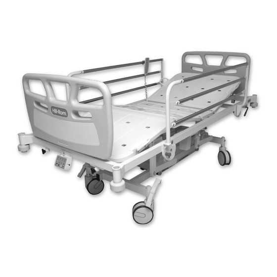
- Page 1 OPERATION AND MAINTENANCE MANUAL Electrically Operated General Ward Product No. FE5000 154588 REV 1...
- Page 3 Hill-Rom® is a registered trademark of Hill-Rom Services, Inc. The information contained in this manual is subject to change without notice. Medicraft Hill-Rom makes no commitment to update or keep current, the information contained in this manual. Medicraft Hill-Rom reserves the right to make changes without notice in design, specifications, and models.
- Page 4 NOTES: Page ii Electrically Operated General Ward Bed Operation and Maintenance Manual (154588 REV 1)
-
Page 5: Table Of Contents
Table of Contents Chapter 1: Introduction Purpose ............1 - 1 Audience . - Page 6 Electromagnetic Emissions and Immunity Guidance ....1 - 20 Model Identification ..........1 - 25 Environmental Conditions for Transport, Storage, and Use.
- Page 7 Chapter 4: Removal, Replacement, and Adjustment Procedures Tool and Supply Requirements........4 - 1 Control Box.
- Page 8 NOTES: Page vi Electrically Operated General Ward Bed Operation and Maintenance Manual (154588 REV 1)
-
Page 9: Chapter 1: Introduction
Chapter 1 Introduction Purpose This manual contains instructions for the operation and maintenance of the Electrically Operated General Ward Bed. It also includes parts lists (in chapter 5) for you to order replacement parts. Audience This manual is intended for use by only facility-authorized persons. To ignore this restriction could cause severe injury to people and serious damage to equipment. -
Page 10: Document Symbols
Document Symbols Chapter 1: Introduction Document Symbols This manual contains different typefaces and symbols to make the content easier to read and understand: • Standard text—used for regular data. • Boldface text—emphasizes a word or phrase. • NOTE:—sets apart special data or important instruction clarification. •... -
Page 11: Installation
Installation Chapter 1: Introduction Installation Unpack and examine the bed. See the steps in the sections below. Unpack the Bed Unpack the bed: 1. Remove all of the bubble-wrap from the bed. 2. Remove the protective foam pad from the end of the bed (see figure 1-1 on page 1-3). - Page 12 Installation Chapter 1: Introduction 7. Keep the power cable combination a safe distance from bed frame parts that move. Keep the power cable wound on the storage hooks (see figure 1- 2 on page 1-4). Figure 1-2. Power Cable Location 8.
-
Page 13: Features
Features Chapter 1: Introduction Features Item Description Item Description Attendant control panel Backrest quick release (safety lockout switches) Infection control sleep deck G Single and twin wheel castors Removable headboards and Brake and steering foot pedals footboards Safety siderails Handset Corner bumpers Electrically Operated General Ward Bed Page 1 - 5... -
Page 14: Handset
Features Chapter 1: Introduction Handset A handset is used to change the bed height, backrest position, knee position, and head and foot up and down positions. WARNING: Children must not be permitted to operate the controls or ride on the bed. - Page 15 Features Chapter 1: Introduction Figure 1-3. Handset Electrically Operated General Ward Bed Page 1 - 7 Operation and Maintenance Manual (154588 REV 1)
-
Page 16: Knee-Break Operation (Optional)
Features Chapter 1: Introduction Knee-Break Operation (Optional) • To raise the section, press the Knee-break Up control (E) until the applicable position is reached. • To lower the section, press the knee-break Down control (F) until the applicable position is reached. Backrest and Knee-Break Operation Combined •... - Page 17 Features Chapter 1: Introduction • Chair position (T) (optional) • Emergency Trendelenberg (S) (can not be locked out) • Light (U) (underbed light) • Key control (W) (for lock/unlock) • Function up (X) • Function down (Y) Figure 1-4. ACP •...
-
Page 18: Backrest Quick-Release
Features Chapter 1: Introduction Backrest Quick-Release WARNING: The quick-release system is to be used for emergency purposes only. Operation of the quick-release system at the incorrect time can cause injury or equipment damage. The backrest actuator is fitted with a quick-release system to let the backrest be lowered quickly in an emergency. - Page 19 Features Chapter 1: Introduction Figure 1-6. Knee-Break Feature The knee-break foot section may be manually tilted down. 1. To tilt the foot section, hold one of the handles (A) with one hand and pull up slightly (see figure 1-7 on page 1-11). 2.
-
Page 20: Steering And Brakes
Features Chapter 1: Introduction Steering and Brakes WARNING: Always engage the brakes after the bed has been repositioned or is unattended. Failure to set the brakes may cause injury. All four castors are controlled by the brake/steer pedal at the foot end of the bed. There are three positions of the lever: •... -
Page 21: Steering
Features Chapter 1: Introduction Figure 1-9. Release the Brakes Steering Step on one of the two green pedals at the foot end of the bed (see figure 1-10 on page 1-13). The head- and foot-end castors are now set up for steering mode. -
Page 22: Safety Siderails
WARNING: Do not use unapproved safety siderails on the bed. Use of unapproved siderails may cause injury or equipment damage. Contact Medicraft Hill-Rom for information on the correct siderails for use on your bed. Page 1 - 14 Electrically Operated General Ward Bed... -
Page 23: Siderails Up Position
Features Chapter 1: Introduction The safety siderails have two locking positions as follows: Siderails Up Position Raise the siderail to the highest position by lifting upwards until it latches and stays in position (see figure 1-11 on page 1-15). Figure 1-11. Siderails Up Position Siderails Down Position To lower a siderail, do as follows: 1. -
Page 24: Telescopic Extension
Features Chapter 1: Introduction Telescopic Extension The telescopic extension feature extends the length of the bed surface. 1. To extend the bed, raise the extension lock lever (A) at the foot end of the bed and gently pull the footboard outward (see figure 1-13 on page 1-16). 2. -
Page 25: Specifications
Specifications Chapter 1: Introduction Specifications Physical Description WARNING: Do not use the product outside the recommended safe working load. To do so could cause patient injury or equipment damage. For a physical description, see table 1-1 on page 1-17. All maximum bed angles shown are with respect to horizontal. - Page 26 Specifications Chapter 1: Introduction Feature Dimension Recommended mattress dimensions Mattress width 905 mm Mattress length 1980 mm 170 mm (maximum) Mattress thickness 430 mm to 865 mm (150 mm single Bed height range wheel castors) 415 mm to 850 mm (150 mm twin wheel castors) 470 mm to 905 mm (200 mm single wheel castors)
- Page 27 Specifications Chapter 1: Introduction Figure 1-14. Bed Dimensions Electrically Operated General Ward Bed Page 1 - 19 Operation and Maintenance Manual (154588 REV 1)
-
Page 28: Electrical Specifications
Specifications Chapter 1: Introduction Electrical Specifications For electrical specifications, see table 1-2 on page 1-20. Table 1-2. Electrical Specifications Condition Range AC Input Power Requirements 240 V AC +/- 10%, .6 A, 50 Hz Battery Backup 1.2 ampere-hour Enclosure Double insulated with functional earth connector, Class One, indoor use only, IPX4 a. - Page 29 Specifications Chapter 1: Introduction The electromagnetic emissions and immunity guidance is given below: Electromagnetic Emissions Guidance Guidance and Manufacturer's Declaration—Electromagnetic Emissions The bed is intended for use in the electromagnetic environment specified below. The customer or the user of the bed should assure that it is used in such an environment.
- Page 30 Specifications Chapter 1: Introduction Electromagnetic Immunity Guidance Guidance and Manufacturer's Declaration - Electromagnetic Immunity The bed is intended for use in the electromagnetic environment specified below. The customer or the user of the bed should assure that it is used in such an environment. IEC 60601 Electromagnetic Immunity Test...
- Page 31 Specifications Chapter 1: Introduction Electromagnetic Immunity Guidance Guidance and Manufacturer's Declaration—Electromagnetic Immunity The bed is intended for use in the electromagnetic environment specified below. The customer or the user of the bed should assure that it is used in such an environment. Immunity IEC 60601 Compliance...
- Page 32 Specifications Chapter 1: Introduction Recommended separation distances between portable and mobile RF communications equipment and the bed The bed is intended for use in an electromagnetic environment in which radiated RF disturbances are controlled. The customer or the user of the bed can help prevent electromagnetic interference by maintaining a minimum distance between portable and mobile RF communications equipment (transmitters) and the bed as recommended below, according to the maximum output power of the communications equipment.
-
Page 33: Model Identification
Specifications Chapter 1: Introduction Model Identification Model Number Description FE5000 Electrically Operated General Ward Bed Environmental Conditions for Transport, Storage, and Use Condition Range Temperature +10° C to +40° C ambient temperature Relative humidity range 30% to 75% Atmospheric pressure range... -
Page 34: Safety Tips
Medicraft Hill-Rom makes a larger style bed for obese patients. A risk assessment of the patient must be done to make sure that the bed and its features are applicable for the patient’s characteristics. - Page 35 Safety Tips Chapter 1: Introduction WARNING: Always do a visual check for obstructions before adjustment of the bed angle and height. Failure to operate the bed safely may cause injury or equipment damage. WARNING: Do not use unapproved safety siderails on the bed. Use of unapproved siderails may cause injury or equipment damage.
-
Page 36: Bed Service
Safety Tips Chapter 1: Introduction WARNING: Remove the possibility of entrapment. Make sure that no part of the patient’s body (head, limb, etc.) is beyond the perimeter of the bed frame or is in the siderail mechanism. Failure to operate the bed safely may cause injury or equipment damage. -
Page 37: Electrical
Safety Tips Chapter 1: Introduction WARNING: Brace the bed using a bed jack, bed stands or other approved method to make sure the bed is braced safely. Failure to brace the bed correctly can cause injury. WARNING: If the knee-break is in the up position, it must be braced before the actuator bolt is removed. - Page 38 Safety Tips Chapter 1: Introduction CAUTION: Make sure the mains supply power cable IEC and quick-release power supply cable IEC socket plug are correctly connected. Failure to correctly connect the cables may cause equipment damage. Page 1 - 30 Electrically Operated General Ward Bed Operation and Maintenance Manual (154588 REV 1)
-
Page 39: Product Symbols
Product Symbols Chapter 1: Introduction Product Symbols Symbol Description Potential Equalization Terminal Safe Working Load (SWL) Applied Part type B Backrest up/down function Backrest up function Knee-break function Knee-break up/down function Knee-break and backrest function (two functions combined) Bed up/down function (HI/LO) Electrically Operated General Ward Bed Page 1 - 31 Operation and Maintenance Manual (154588 REV 1) - Page 40 Product Symbols Chapter 1: Introduction Symbol Description Trendelenburg tilt function (head down) (electric models) Trendelenburg tilt function (electric models) Chair position function (move into seated position) Power on function Bed level function Emergency trendelenburg Function Key Underbed light Up/down direction function a.
-
Page 41: Warning And Caution Labels
Warning and Caution Labels Chapter 1: Introduction Warning and Caution Labels Warning label for pinch or shear point Electrically Operated General Ward Bed Page 1 - 33 Operation and Maintenance Manual (154588 REV 1) - Page 42 Warning and Caution Labels Chapter 1: Introduction NOTES: Page 1 - 34 Electrically Operated General Ward Bed Operation and Maintenance Manual (154588 REV 1)
-
Page 43: Chapter 2: Troubleshooting Procedures
To make sure the repair corrected the problem, do the Final Actions after the Function Checks. If troubleshooting procedures do not identify the problem, contact Medicraft Hill-Rom Technical Support. Electrically Operated General Ward Bed Page 2 - 1 Operation and Maintenance Manual (154588 REV 1) -
Page 44: Initial Actions
Initial Actions Chapter 2: Troubleshooting Procedures Initial Actions To gather information from operators about problems with the bed, use Initial Actions. Make note of the symptoms or other information about the problem the operator describes. This information helps identify the probable cause. 1. -
Page 45: Function Checks
Function Checks Chapter 2: Troubleshooting Procedures Function Checks 1. Initial Actions have been performed. Go to “Initial Actions” on page 2-2. 2. Set the brakes, raise and lock the siderails in the high position. Plug the power cord into an applicable power source. 3. - Page 46 Function Checks Chapter 2: Troubleshooting Procedures 9. Press the Knee Up control. The knee section rises to the high position without stopping or the audible alarm sounding. Go to RAP 2.3. 10. Press the Knee Down control. The knee section goes down to the low position without stopping or the audible alarm sounding.
- Page 47 Function Checks Chapter 2: Troubleshooting Procedures The head section descends quickly to the mid-position then slows until the flat position is reached. Repeat for the other CPR control handle. The control function operates correctly. Go to RAP 2.8. 17.
-
Page 48: Final Actions
Final Actions Chapter 2: Troubleshooting Procedures Final Actions 1. Complete the necessary preventive maintenance procedures. See “Preventive Maintenance Checklist” on page 6-5. 2. Complete all necessary administrative tasks. Page 2 - 6 Electrically Operated General Ward Bed Operation and Maintenance Manual (154588 REV 1) -
Page 49: No Functions Work
Move the bed to a power outlet that is functional. 5. Examine the mains power cable for damage. Replace if damaged. 6. Contact Medicraft Hill-Rom Customer Service. Electrically Operated General Ward Bed Page 2 - 7 Operation and Maintenance Manual (154588 REV 1) -
Page 50: Lockout Malfunction
3. Replace the control box with a known good control box. The problem continues. Replace the control box. Go to “Function Checks” on page 2-3. 4. Contact Medicraft Hill-Rom Customer Service. Page 2 - 8 Electrically Operated General Ward Bed Operation and Maintenance Manual (154588 REV 1) -
Page 51: Knee-Break Malfunction
2.3 Knee-Break Malfunction Chapter 2: Troubleshooting Procedures Knee-Break Malfunction 1. Does at least one of the other functions operate correctly? Go to RAP 2.1 on page 2-7. 2. Is the knee-break lockout function unlocked? Unlock the knee-break function. 3. - Page 52 The problem continues. Go to “Final Actions” on page 2-6. 9. Contact Medicraft Hill-Rom Customer Service. Page 2 - 10 Electrically Operated General Ward Bed Operation and Maintenance Manual (154588 REV 1)
-
Page 53: Hi/Lo Malfunction
2.4 HI/LO Malfunction Chapter 2: Troubleshooting Procedures HI/LO Malfunction 1. Does at least one of the other functions operate correctly? Go to RAP 2.1 on page 2-7. 2. Is the HI/LO lockout function unlocked? Unlock the HI/LO function. 3. - Page 54 The problem continues. Go to “Final Actions” on page 2-6. 9. Contact Medicraft Hill-Rom Customer Service. Page 2 - 12 Electrically Operated General Ward Bed Operation and Maintenance Manual (154588 REV 1)
-
Page 55: Backrest Malfunction
2.5 Backrest Malfunction Chapter 2: Troubleshooting Procedures Backrest Malfunction 1. Does at least one of the other functions operate correctly? Go to RAP 2.1 on page 2-7. 2. Is the backrest lockout function unlocked? Unlock the backrest function. 3. - Page 56 The problem continues? Go to “Final Actions” on page 2-6. 9. Contact Medicraft Hill-Rom Customer Service. Page 2 - 14 Electrically Operated General Ward Bed Operation and Maintenance Manual (154588 REV 1)
-
Page 57: Battery Backup Malfunction
2-3. 5. Replace the battery. The problem continues. Go to “Final Actions” on page 2-6. 6. Contact Medicraft Hill-Rom Customer Service. Electrically Operated General Ward Bed Page 2 - 15 Operation and Maintenance Manual (154588 REV 1) -
Page 58: Trendelenburg Malfunction
Replace the affected control box. Go to “Function Checks” on page 2-3. 6. Contact Medicraft Hill-Rom Customer Service. Page 2 - 16 Electrically Operated General Ward Bed Operation and Maintenance Manual (154588 REV 1) -
Page 59: Cpr Malfunction
4. Replace the backrest motor. Does the problem continue? Go to “Final Actions” on page 2-6. 5. Contact Medicraft Hill-Rom Customer Service. Electrically Operated General Ward Bed Page 2 - 17 Operation and Maintenance Manual (154588 REV 1) -
Page 60: Brake Or Steering Malfunction
4. Replace the backrest motor. Does the problem continue? Go to “Final Actions” on page 2-6. 5. Contact Medicraft Hill-Rom Customer Service. Page 2 - 18 Electrically Operated General Ward Bed Operation and Maintenance Manual (154588 REV 1) -
Page 61: Chapter 3: Theory Of Operation
Chapter 3 Theory of Operation Electrical System HI/LO A dual actuator system operates the HI/LO function. The actuators extend at the same time to raise the bed. The actuators retract at the same time to lower the bed. Backrest A single actuator extends to raise and retracts to lower the backrest. This actuator is also fitted with a cable-operated quick release system. -
Page 62: Backrest And Knee-Break
Electrical System Chapter 3: Theory of Operation Backrest and Knee-Break One control operates both the backrest and the knee-break function at the same time. The knee-break will reach the end of stroke before the backrest. The knee-break actuator is fitted with internal limit switches so it will stop at the end of the stroke. -
Page 63: Chapter 4: Removal, Replacement, And Adjustment Procedures
Chapter 4 Removal, Replacement, and Adjustment Procedures Tool and Supply Requirements To service the Electrically Operated General Ward Bed, these tools and supplies are necessary: • #2 phillips screwdriver • 11 mm hex wrench • 11 mm spanner wrench • 13 mm spanner wrench •... -
Page 64: Control Box
4.1 Control Box Chapter 4: Removal, Replacement, and Adjustment Procedures Control Box Tools required: Screwdriver #2 phillips screwdriver 11 mm spanner wrench Removal SHOCK HAZARD: Failure to unplug the unit from its power source could cause injury or equipment damage. 1. - Page 65 4.1 Control Box Chapter 4: Removal, Replacement, and Adjustment Procedures CAUTION: Support the control box. Failure to support the control box as the fasteners are removed will cause damage to the plastic housing and void the warranty. 7. Support the control box and remove the four fasteners (A) that secure the control box to the bed frame (see figure 4-2 on page 4-3).
-
Page 66: Hi/Lo Actuator
4.2 HI/LO Actuator Chapter 4: Removal, Replacement, and Adjustment Procedures HI/LO Actuator Tools required: Screwdriver #2 phillips screwdriver Pliers Bed stands or bed jack Removal SHOCK HAZARD: Failure to unplug the unit from its power source could cause injury or equipment damage. - Page 67 4.2 HI/LO Actuator Chapter 4: Removal, Replacement, and Adjustment Procedures 5. Remove and keep the four screws (A) and base cover (B) (see figure 4-4 on page 4-5). Figure 4-4. Wheelbase Cover 6. Remove the wire-ties and wire clamps as necessary to remove the cabling of the actuator to be replaced.
- Page 68 4.2 HI/LO Actuator Chapter 4: Removal, Replacement, and Adjustment Procedures 8. Disconnect the cable-to-control box connection as required to allow the actuator to be removed from the bed. NOTE: The type of cable from the actuator will vary depending on the configuration and date of manufacture.
- Page 69 4.2 HI/LO Actuator Chapter 4: Removal, Replacement, and Adjustment Procedures – For plug-in type configurations, unplug the cable directly at the actuator (see figure 4-8 on page 4-7). Figure 4-8. Plug-in Cable Configuration NOTE: In addition to the control box cable above, some systems may include SLS limit switches.
-
Page 70: Backrest Actuator
4.3 Backrest Actuator Chapter 4: Removal, Replacement, and Adjustment Procedures Backrest Actuator Tools required: Screwdriver 17 mm spanner wrench #2 phillips screwdriver Bed stand Removal This procedure covers both 150 mm and 200 mm backrest actuators. SHOCK HAZARD: Failure to unplug the unit from its power source could cause injury or equipment damage. - Page 71 4.3 Backrest Actuator Chapter 4: Removal, Replacement, and Adjustment Procedures – For mini-fit configurations, remove the retaining clip and unplug the in-line socket (see figure 4-9 on page 4-9). Figure 4-9. Mini-Fit Cable Configuration – For hard-wired configurations, access the sockets by removing the saddle.
- Page 72 4.3 Backrest Actuator Chapter 4: Removal, Replacement, and Adjustment Procedures Replacement CAUTION: Cable routing, clamps, and cable ties must be replaced as per the original installation. Failure to install items correctly can cause damage to the cables. 1. Reverse the procedures to install the new actuator. 2.
-
Page 73: Knee-Break Actuator
4.4 Knee-break Actuator Chapter 4: Removal, Replacement, and Adjustment Procedures Knee-break Actuator Tools required: Screwdriver 17 mm spanner wrench #2 phillips screwdriver Bed stand Removal SHOCK HAZARD: Failure to unplug the unit from its power source could cause injury or equipment damage. - Page 74 4.4 Knee-break Actuator Chapter 4: Removal, Replacement, and Adjustment Procedures NOTE: The type of cable from the actuator will vary depending on the configuration and date of manufacture. – For mini-fit configurations, remove the retaining clip, and unplug the in-line socket (see figure 4-13 on page 4-12). Figure 4-13.
- Page 75 4.4 Knee-break Actuator Chapter 4: Removal, Replacement, and Adjustment Procedures – For plug-in configurations, unplug the cable directly at the actuator (see figure 4-15 on page 4-13). Figure 4-15. Plug-In Cable Configuration Replacement 1. Reverse the procedures to install the replacement actuator. CAUTION: Cable routing, clamps, and cable ties must be replaced as per the original installation.
-
Page 76: Castor
4.5 Castor Chapter 4: Removal, Replacement, and Adjustment Procedures Castor Tools required: 13 mm spanner wrench 11 mm hex wrench 5/32 hex wrench Screwdriver Hammer 18 mm drive socket 3/4" drive socket 3/16" punch Bed stand or bed jack Removal WARNING: Brace the bed using a bed jack, bed stands or other approved method to make sure the bed is braced safely. - Page 77 4.5 Castor Chapter 4: Removal, Replacement, and Adjustment Procedures – Tracking castors are identified by a black ring at the top of the castor stem (see figure 4-16 on page 4-15). Figure 4-16. Tracking Castor – Brake castors are identified by a silver ring at the top of the castor stem (see figure 4-17 on page 4-15).
- Page 78 4.5 Castor Chapter 4: Removal, Replacement, and Adjustment Procedures 2. Hold the new castor (oriented as it will be installed) and use a 11 mm hex key (or a short piece of 11 mm hex bar) and put the brake pedal in the brake position (see figure 4-18 on page 4-16).
- Page 79 4.5 Castor Chapter 4: Removal, Replacement, and Adjustment Procedures 9. Slide the hex bar into the castor. 10. Set the brakes. 11. Install the brake pedal or helmet cap. NOTE: Make sure that the grub screw on the brake pedal is securely tightened. NOTE: A drive socket of 18 mm can be used to assist in the installation of the helmet cap.
- Page 80 4.5 Castor Chapter 4: Removal, Replacement, and Adjustment Procedures 3. Test the individual castors by rotating by hand. If a castor can be rotated by hand, the braking is not sufficient. 4. Remove the two mount bolts that secure the castor to the base. 5.
-
Page 81: Chapter 5: Parts List
Chapter 5 Parts List Service Parts Ordering Use the parts lists in this manual to identify the necessary part number(s). Find the product number and serial number on the product identification label (A) (see figure 5-1 on page 5-1). Figure 5-1. Product Identification Label Location Electrically Operated General Ward Bed Page 5 - 1 Operation and Maintenance Manual (154588 REV 1) - Page 82 Service Parts Ordering Chapter 5: Parts List Contact Medicraft Hill-Rom Technical Support at (02) 9569 0255 with the data that follows: • Purchase order number • Product number • Serial number • Part number(s) To promptly order parts, request part prices and availability, or follow up on a service order, contact Medicraft Hill-Rom: •...
-
Page 83: Exchange Policy
Medicraft Hill-Rom requests to be returned. In some cases, the invoice accompanying the parts will show the full selling price (only for internal use at Medicraft Hill-Rom). Do not confuse this price with your price. Do not return any parts without a RMA number. When parts/products have been requested to be returned, Medicraft Hill-Rom will include an RMA packet with the parts/products shipment. - Page 84 Exchange Policy Chapter 5: Parts List NOTES: Page 5 - 4 Electrically Operated General Ward Bed Operation and Maintenance Manual (154588 REV 1)
-
Page 85: Warranty
Medicraft Hill-Rom, found to be defective. In addition to the foregoing five-year warranty, Medicraft Hill-Rom warrants to the original purchaser that the frame and welds on its products will be free from structural defects for ten (10) years. Any product upgrade or modification initiated by Medicraft Hill-Rom does not affect the original product warranty. - Page 86 Warranty Chapter 5: Parts List NOTES: Page 5 - 6 Electrically Operated General Ward Bed Operation and Maintenance Manual (154588 REV 1)
-
Page 87: Recommended Spare Parts
Recommended Spare Parts Chapter 5: Parts List Recommended Spare Parts See table 5-1 on page 5-7 for a recommended spare parts list to service ten units. Table 5-1. Recommended Spare Parts Part Number Quantity Description 713279 ACP, Linak®, (electric tilt) 713283, 713284, FE control box, Linak®... -
Page 88: Sleep Deck
Sleep Deck Chapter 5: Parts List Sleep Deck Figure 5-2. Sleep Deck Page 5 - 8 Electrically Operated General Ward Bed Operation and Maintenance Manual (154588 REV 1) - Page 89 Sleep Deck Chapter 5: Parts List Table 5-2. Sleep Deck Item Number Part Number Quantity Description 710181 ICO foot section panel 710182 ICO handles 710180 ICO middle section panel 710179 ICO fixed section panel 710178 ICO backrest panel 710208 Cone lock nut, M8 710167 Flat washer, M8, 17 mm x 1.2 mm 710012...
-
Page 90: Articulating Frame
Articulating Frame Chapter 5: Parts List Articulating Frame Figure 5-3. Articulating Frame Page 5 - 10 Electrically Operated General Ward Bed Operation and Maintenance Manual (154588 REV 1) - Page 91 Articulating Frame Chapter 5: Parts List Table 5-3. Articulating Frame Item Number Part Number Quantity Description 710509 Swing, inner 710443 Threaded bushing, M8 x 50 710524 Swing, telescopic axle pin 710066 Helmut cap, 12 mm 710664 Swing, telescopic outer, ET 713272 Main lift, Linak®, Mini-Fit 710204...
-
Page 92: Lower Frame
Lower Frame Chapter 5: Parts List Lower Frame Figure 5-4. Lower Frame Page 5 - 12 Electrically Operated General Ward Bed Operation and Maintenance Manual (154588 REV 1) - Page 93 Lower Frame Chapter 5: Parts List Table 5-4. Lower Frame Item Number Part Number Quantity Description 710203 Power box cover 710442 U-bolt, M10, 46 mm ID 710290 Screw, self tapping #8 x 1/2" pan head 710441 Split bushing, plastic 710528 Gas strut, 900N 710066 Helmut cap, 12 mm...
-
Page 94: Upper Frame
Upper Frame Chapter 5: Parts List Upper Frame Figure 5-5. Upper Frame Page 5 - 14 Electrically Operated General Ward Bed Operation and Maintenance Manual (154588 REV 1) - Page 95 Upper Frame Chapter 5: Parts List Table 5-5. Upper Frame Item Number Part Number Quantity Description 713279 ACP, Linak®, (electric tilt) 710555 FE50001 telescopic extension (280 kg) 712370 FE50001 telescopic extension (300 kg) 713031 FE50002 telescopic extension (250 kg) 712901 FE50002 telescopic extension (280 kg) 712900 FE50002 telescopic extension (300 kg)
- Page 96 Upper Frame Chapter 5: Parts List Item Number Part Number Quantity Description 710107 Bolt, high tensile, M6 x 45 710112 Split pin (not on FE50003) 710141 Rubber buffer (FE50001 only) 712940 Rubber buffer (FE50002 and FE50003) 710221 Buffer washer, 50 mm OD x 40 mm ID (not on FE50003) 713278 Handset, backlit (Linak®) (microproces-...
-
Page 97: Chapter 6: General Procedures
General Procedures Clean and Disinfect Regular cleaning is necessary to keep the Medicraft Hill-Rom bed in a clean and functional condition. To clean with detergent helps remove soil and decrease the amount of microorganisms from the surface. The frequency of cleaning must be determined by each facility. -
Page 98: Electrical Components Cleaning
Electrical Components Cleaning Chapter 6: General Procedures 11. Lower the backrest. 12. Fully elevate the knee-break, fold the mattress and repeat the cleaning procedure for the lower half of the bed. 13. Reposition the mattress on the base. 14. Raise the siderails and clean them. 15. -
Page 99: Storage And Transport
Storage and Transport Chapter 6: General Procedures Storage and Transport • Examine the mains power supply cable and all other cables for damage and replace as necessary. • Put the mains power supply cable on the storage hooks and attach the handset to the headboard frame when the bed is transported. -
Page 100: Preventive Maintenance
Preventive Maintenance Chapter 6: General Procedures Preventive Maintenance WARNING: Only approved persons are permitted to service the bed. Service done by unapproved persons may cause injury or equipment damage. Only approved persons are permitted to service the bed. Preventive Maintenance Schedule The table that follows is a twelve month recommended maintenance schedule (see table 6-1 on page 6-4). -
Page 101: Preventive Maintenance Checklist
Preventive Maintenance Chapter 6: General Procedures Preventive Maintenance Checklist Use the preventive maintenance checklist to record maintenance activities performed on the Electrically Operated General Ward Bed. Date Function Battery backup Bed frame Bed (parts that move) Castors Fasteners Metal surfaces Labor Time: Repair Cost: Inspected by:... - Page 102 Preventive Maintenance Chapter 6: General Procedures NOTES: Page 6 - 6 Electrically Operated General Ward Bed Operation and Maintenance Manual (154588 REV 1)
-
Page 103: Chapter 7: Accessories
Chapter 7 Accessories Accessories Table 7-1. Accessories List Product Number Description 710777 Orthopedic frame 712338 Orthopedic half frame 710784 IV pole (32 mm bayonet) 710775 Self-help pole 712815 Monitor shelf 710774 Oxygen bottle holder (size PR, underbed) 710773 Oxygen bottle holder (size PR, clip-on) 712946 Oxygen bottle holder (Inhalo, underbed) 712394... -
Page 104: Orthopedic Frame
7.1 Orthopedic Frame Chapter 7: Accessories Orthopedic Frame Tools required: None Installation 1. Install the uprights (A) into the corner sockets of the bed (see figure 7-1 on page 7-3). 2. Install the parallel bars (B). Do not tighten the clamp at this time. NOTE: Allow the parts to float until the assembly is completed. - Page 105 7.1 Orthopedic Frame Chapter 7: Accessories Figure 7-1. Orthopedic Frame Electrically Operated General Ward Bed Page 7 - 3 Operation and Maintenance Manual (154588 REV 1)
-
Page 106: Orthopedic Half Frame
7.2 Orthopedic Half Frame Chapter 7: Accessories Orthopedic Half Frame Tools required: None The Orthopedic half frame is a removable, adjustable device that installs into the corners of the bed. Installation 1. Install the uprights (A) into the corner sockets of the bed (see figure 7-2 on page 7-4). - Page 108 Fax: +81 (0)3 5715 3425 Nederland New Zealand Nordic Region: Hill-Rom Medical Services BV c/o Hill-Rom Australia Pty. Ltd. Sverige, Denmark, Norge Tel: +31 (0)347 / 32 35 32 Tel: 61 (0)2 8814 3000 Hill-Rom AB Fax: +31 (0)347 / 32 35 00...
Need help?
Do you have a question about the FE5000 and is the answer not in the manual?
Questions and answers