Table of Contents
Advertisement
Quick Links
Advertisement
Table of Contents

Related Manuals for CAME G3250


Summary of Contents for CAME G3250
- Page 1 Street barriers FA01213-EN G3250 INSTALLATION MANUAL EN English...
- Page 2 THE BARRIER S MANEUVERING AREA EEP ANY REMOTE CONTROL TRANSMITTERS HIS PRODUCT SHOULD ONLY BE USED FOR THE PURPOSE FOR WHICH IT WAS . CAME S. OR ANY OTHER COMMAND DEVICE AWAY FROM CHILDREN TO PREVENT THE EXPLICITLY DESIGNED NY OTHER USE IS DANGEROUS IS NOT •...
- Page 3 The automatic barrier is designed for private and public parking facilities. Any installation and/or use other than that specified in this manual is forbidden. Limits to use Model G3250 Maximum clearance width of the passage (m) 3.25 Technical data Model...
-
Page 4: Standard Installation
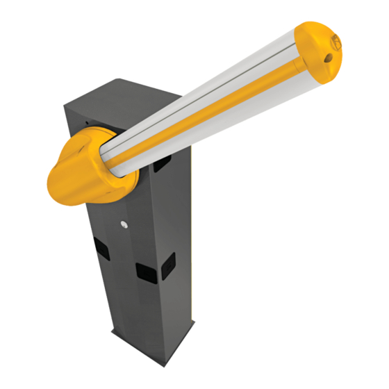
Description of parts Cabinet Gearmotor Transmission-shaft plate Control panel Boom-attachment cover Balancing spring Anti-shearingprotective cover 10. Inspectionhatch Gearmotor release with customized key Hatch lock with customized key Standard installation Barrier Photocells post Flashing light Fixed rest Semi-oval boom 10. Control device (keypad, magnetic key, transponder, etc.) Luminous cord 11. -
Page 5: Preliminary Checks
GENERAL INSTRUCTIONS FOR INSTALLING ⚠ Only skilled, qualified staff must install this product. Important! Using original CAME control and safety devices and accessories ensures easy installation and system maintenance. Preliminary checks ⚠ Before beginning, do the following: • make sure the plate is anchored to a solid spot;... - Page 6 INSTALLING ⚠ The following illustrations are mere examples. Consider that the space available where to fit the barrier and accessories will vary depending on the area where it is installed. It is up to the installer to find the most suitable solution. ⚠ ...
- Page 7 Place the plate over the iron cage. Fill the foundation frame with concrete. The base must be perfectly level with the bolts which are entirely above surface. Wait at least 24 hrs for the concrete to solidify. Remove the foundation frame. Fill the hole with earth around the concrete block.
- Page 8 Place the cabinet onto the anchoring plate and fasten it using nuts and washers. M12 UNI 5588 nut Washer To change the rotation at a later date, request the documentation from your local retailer or contact Came in your Country (see the last page or visit www.came.com) Entry side...
- Page 9 The luminous cord can only be cut at the points marked by the scissors icon, that is, at every meter. I L I Luminous cord length = l x 2 + 0.5 m Fit the insulating cap to one end of the luminous cord. Press the luminous cord into the boom's groove, as shown in the picture.
- Page 10 Place the boom-attachment cover against the transmission shaft plate; use only one screw and leave it loose. UNI 5931 M8x12 Fit the boom into the attachment cover - make sure the power cable is inside the boom's conduit. Plug the power supply cable into the luminous cord. If the luminous cord does not work, invert/rotate the plug, then isolate the junction point with heat-shrunk sheath.
- Page 11 Push the boom up vertically to fasten it between the attachment cover and the transmission-shaft plate. UNI 5931 M8x12 Fasten the boom by using the remaining screws. Fit and fasten the anti-shearing protective cover onto the boom attachment- cover.
- Page 12 Balancing the boom Release the gearmotor and loosen the rod nut. Fastening nut RELEASING Manually turn the balancing spring to increase or reduce the traction force so that the boom balances at a 45-degree angle. Fasten the rod nut and lock the gearmotor.
-
Page 13: Description Of Parts
ELECTRICAL CONNECTIONS AND PROGRAMMING ⚠ Warning! Before working on the control panel, cut off the main current supply and, if present, remove any batteries. Power supply to the control panel and control devices: 24 V AC/DC. Use DIP switches to set functions and the trimmer for adjustments. All connections are quick-fuse protected. - Page 14 Power supply Terminals for powering up accessories: - a 24 V AC normally; 230 V AC, 50/60 Hz - a 24 V DC when the emergency batteries are operating; Overall allowed power: 40 W Eyelet terminal with screw and washer for grounding connection.
-
Page 15: Safety Devices
Command and control devices STOP button (NC contact). For stopping the boom while excluding the automatic closing. To resume movement either press the control button or any other control device. If unused, set DIP switch 9 to ON. OPEN ONLY function from control device with NO contact. Warning: in MAINTAINED ACTION mode, the control device must be connected to 2-3 ONLY OPEN or OPEN-CLOSED-INVERT (step-step) function from control device (NO contact, see DIP switch... - Page 16 Adjusting speed Min. = minimum Med. = medium Max. = maximum COM = common DIS. 27370 Max. Med. Min. Min. Max. To regulate the travel speed, move To adjust the slow-down speed, move faston A on Min., Med. or Max. faston B to Min.
- Page 17 Keep pressed the PROG programming button on the control board. The programming LED fl ashes. Press any key on the transmitter you want to memorize. The LED stays on to indicate that memorization has been successful. PROG key Programming LED ...
- Page 18 To correct the horizontal, closed, position, raise the boo, adjust the closing mechanical stop and fasten it by using the counter nut. Counter nut Mechanical closing stop Programming the features Default settings 3 4 5 6 7 8 9 10 DIP-SWITCH Description of functions 1 ON AUTOMATIC CLOSING (1 OFF - deactivated)
-
Page 19: Trimmer Adjustments
Trimmer adjustments 3 4 5 6 7 8 9 10 Trimmer Description of functions Sensibility SENS It adjusts the obstruction detection sensitivity during gate movement. Minimum sensitivity (-) or maximum sensitivity (+). Automatic Closing Time A.C.T. It adjusts the barrier's waiting time when it is open. Once this time elapses, a closing maneuver is automatically performed. The waiting time may be adjusted to between 1 and 120 seconds FINAL OPERATIONS ... -
Page 20: Troubleshooting
RELEASING THE BOOM ⚠ This procedure must be done with the main power cut off . Fit the key into the lock and turn it clockwise . Manually raise the boom and lock it back into pace by turning the key counter clockwise ⚠ ... - Page 21 PAIRED CONNECTION WITH A SINGLE COMMAND Establish the Master and the Slave barrier. MASTER SLAVE On the MASTER barrier's electronic board, make the necessary electrical connections, activate the radio control, program the functions and settings. MASTER 3 4 5 6 7 8 9 10 On the SLAVE barrier's control board, connect the power supply to L-N, the fl...
-
Page 22: Maintenance Log
MAINTENANCE LOG Periodic maintenance ☞ Before doing any maintenance, cut off the power supply, to prevent any hazardous situations caused by accidental boom movements. Periodic maintenance log kept by users (every six months) Date Notes Signature Extraordinary maintenance ⚠ The following table is for logging any extraordinary maintenance jobs, repairs and improvements performed by specialized contractors. ... -
Page 23: Dismantling And Disposal
____________________________________________________________________________________________ DISMANTLING AND DISPOSAL ☞ CAME S.p.A. applies a certified Environmental Management System at its premises, which is compliant with the UNI EN ISO 14001 standard to ensure the environment is safeguarded. Please continue safeguarding the environment. At CAME we consider it one of the fundamentals of our operating and market strategies. Simply... - Page 24 CAME S.p.A. Via Martiri Della Libertà, 15 31030 Dosson di Casier - Treviso - Italy tel. (+39) 0422 4940 - fax. (+39) 0422 4941...
Need help?
Do you have a question about the G3250 and is the answer not in the manual?
Questions and answers