
Related Manuals for CAME G5000


Summary of Contents for CAME G5000
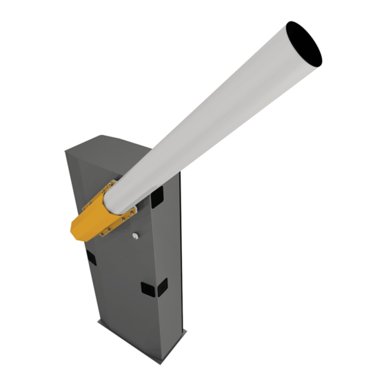
- Page 1 Automatic barrier FA00571-EN - GARD series G5000 English INSTALLATION OPERATION AND MAINTENANCE MANUAL...
- Page 3 HIS PRODUCT SHOULD ONLY BE USED FOR THE PURPOSE FOR WHICH IT WAS EXPLICITLY DESIGNED . • T NY OTHER USE IS DANGEROUS IS NOT LIABLE FOR ANY DAMAGE CAUSED BY IMPROPER WRONGFUL AND UNREASONABLE USE HIS PRODUCT SUPPLIED CAME S. " ", 2006/42/CE. P IS CONSIDERED TO BE PARTLY...
- Page 4 MANUAL RELEASE Warning! This operation is potentially hazardous for user, when for whatever reason, such as the boom being badly fastened, ripped out or broken during an accident, and so on, the loosened springs no longer provide the proper balancing action. This could lead to a sudden rotation of the boom attachment and/or of the boom itself.
- Page 5 GENERAL PRECAUTIONS FOR INSTALLERS CAUTION! Important safety instructions. Follow all of these instructions. Improper installation can cause serious bodily harm. Before continuing, also read the general precautions for users. S.P.A. HIS PRODUCT MUST ONLY BE USED FOR ITS SPECIFICALLY INTENDED PURPOSE NY OTHER USE IS DANGEROUS IS NOT LIABLE FOR ANY DAMAGE CAUSED .
- Page 6 INTENDED USE The automatic barrier is designed for private and public parking facilities. Any installation and/or use other than that specified in this manual is forbidden. OPERATING LIMITS Model G5000 Maximum clearance width of the passage (m) 5000 TECHNICAL DATA Model...
- Page 7 DESCRIPTION OF PARTS 1. Cabinet 8. Transmission lever 2. Drive-shaft plate 9. Mechanical opening stop 3. Boom attachment-cover 10. Balancing springs 4. Gearmotor release lock 11. Control panel 5. Inspection-hatch lock 12. Inspection hatch 6. Gearmotor 13. Anchoring plate 7. Mechanical closing stop 14.
- Page 8 GENERAL INSTRUCTIONS FOR INSTALLING Only skilled, qualified staff must install this product. PRELIMINARY CHECKS Before beginning, do the following: • make sure the plate is anchored to a solid spot; • check that there are no obstruction or impediments near the cabinet;• set up suitable tubes and conduits for the electric cables to pass through, making sure they are protected from any mechanical damage.
- Page 9 INSTALLING The following illustrations are mere examples. Consider that the space available where to fit the barrier and accessories will vary depending on the area where it is installed. It is up to the installer to find the most suitable solution. SETTING UP THE ANCHORING PLATE If the flooring does not allow for a sturdy fastening of the entry unit, you will have to set up a cement slab.
- Page 10 Fill the hole with earth around the concrete block. Remove the nut and washer from the bolts Fit the electric cables into the tubes so that they come out about 600 mm. SETTING UP THE BARRIER Warning! Use hoisting equipment to transport and position the barrier. The mounting must be done by at least two people. During the initial mounting and fastening, the barrier may be unstable and could tip over.
- Page 11 LEFT RIGHT The barrier is set up for installing on the left. If installing on the right side, invert the opening direction, in the following way: - release the gearmotor, loosen the screws from the rods ❶; - remove the transmission lever from the lever arm ❷; - free up the lever arm from the drive shaft by removing the screws and elastic dowels ❸;...
- Page 12 FASTENING THE BARRIER Place the cabinet onto the anchoring plate and fasten it using nuts and washers. Calculate the boom length by taking into account the passage width clearance. Cut off any excess. LENGTH OF BOOM 362 mm 001G0502 Semi-oval section boom made of white varnished aluminum.
- Page 13 BALANCING THE BOOM The barrier is supplied with two Ø 50 mm springs (001G04060). The springs are fitted to the level arm (in holes B). Depending on the final configuration of the barrier, you may have to exclude one of the springs or change the fastening position (see the tables below).
- Page 14 Release the gearmotor and loosen the rod nut. Manually turn the spring to increase or reduce the traction. The boom should stabilize at 45°. Fit the nut to fasten the rod to the spring and tighten it. Lock the gearmotor once again. Check the proper working state of the spring.
- Page 15 CONTROL PANEL Warning! Before working on the control panel, cut off the main power supply and, if present, remove any batteries. Power supply to the control panel and control devices: 24 V AC/DC. Functions on input and output contacts and time and user management details, are set up and viewable on the control panel's display. All wiring connections are quick-fuse protected.
- Page 16 ELECTRICAL CONNECTIONS Connect all wires and cables in compliance with the law while using suitable cable glands, as shown in the drawing. Use a cable gland only for the 230 V AC power supply cable. The electrical cables must not touch any heated parts such as the motor, transformer, and so on. FACTORY WIRING The gearmotor is already connected.
- Page 17 POWER SUPPLY EMC01 FILTER Output to power 24 V AC accessories (normally) - max. 40 W. 230 V AC - 50/60 Hz If the power is out, you can power up the 24 V DC accessories by using buffer batteries. SIGNALING DEVICES Output to notify the state of the barrier (Contact rated for: 24 V AC - 3 W max.).
- Page 18 CONTROL DEVICES Black Transponder or card reader Blue Keypad selector White OPEN-CLOSE-INVERT function (step-step) from control device (NO contact). ONLY CLOSE function from control device (NO contact). Warning: in MAINTAINED ACTION mode, the control device must be connected to 2-4. Warning! OPEN ONLY function from control device with NO contact.
- Page 19 SAFETY DEVICES Photocells Configure contact CX or CY (NC), safety input for photocells. See function ofInput CX (function F2) or CY (function F3) in: C1 reopening while closing. When the barrier is closing, opening the contact causes its movement to invert until fully opened; C4 obstruction wait.
- Page 20 2 3 3P 4 5 7 CX CY 10 11 E1 E6 Rx Tx 1 2 3 3P 4 5 7 CX CY CONNECTION FOR PAIRED OR ALTERNATE OPERATION OR FOR CAME REMOTE PROTOCOL (CRP) UTP CAT 5 Fit the RSE card.
- Page 21 ESTABLISHING THE LIMIT-SWITCH POINTS Close the inspection hatch and power up the system. Move the boom the check that it is parallel to the road surface when closed and at about 89° when open. The barrier's opening and closing maneuvers must be performed with the inspection hatch closed. To correct the boom's vertical position: - lower the boom;...
- Page 22 PROGRAMMING DESCRIPTION OF THE PROGRAMMING COMMANDS Display S1 GND The ENTER key is for: The ESC button is for: - entering menus; - exiting menus; - confirming or memorizing set values. - cancelling changes. The < > keys are for: - moving from one item to another;...
- Page 23 With the barrier closed, open, or after a total stop, the gearmotor stays idle if the safety devices, Obstruction detection that is, the photocells, detect an obstruction. with motor stopped 0 = Deactivated (default) / 1 = Activated It signals the barrier's state The signal device is connected to contact 10-5. State of barrier 0 = on with boom raised and moving (default) / 1 = it fl...
- Page 24 This function only appears if the Encoder function is activated. point 1 = 1% of the total travel /… / 20 = 20% of the total travel To enable operation in paired, alternate or CRP (Came Remote Protocol) modes. Managing the serial connection 0 = Deactivated (default) / 1 = Paired / 2 = Alternate / 3 = CRP Saving memorized users and settings in the memory roll.
- Page 25 For setting the communication speed used in the CRP (Came Remote Protocol) connection system. COM speed 0 = 1200 Baud / 1 = 2400 Baud / 2 = 4800 Baud / 3 = 9600 Baud / 4 = 14400 Baud / 5 = 19200 Baud / 6 = 38400 Baud (default) / 7 = 57600 Baud / 8 = 115200 Baud Entering up to 250 users and associating to each one a function of choice among those included.
- Page 26 SETTING UP Once the connections are all set, have skilled, qualified staff commission the barrier into service. Before continuing, make sure that the way is clear from any obstruction. Power up and begin configuring the system. Important! Start programming by first doing the following functions: - type of boom (see function A1);...
- Page 27 MANAGING USERS When adding/deleting users, the flashing numbers that appear, are numbers that can be used for other users you may wish to add (maximum 25 users). Before registering the users, make sure the AF radio-frequency card is fitted into the connector (see paragraph called CONTROL DEVICES).
- Page 28 SAVING AND UPLOADING ALL DATA (USERS AND CONFIGURATION) WITH THE MEMORY ROLL Procedure for memorizing all of the system's user and configuration data by using the Memory Roll, so they can be used with another control board, even on another system. Warning! Fitting and extracting the Memory Roll must be done with the mains power disconnected.
- Page 29 ERROR MESSAGE The error messages appear on display or are notified by the LEDs. The boom travel calibration was interrupted by the activation of the STOP button. Encoder is broken. Services test error. Insufficient working time. Maximum number of obstructions detected. Transformer overheated / inspection hatch open / boom detached from gearmotor.
- Page 30 ALTERNATE FUNCTION Important! Start by doing the following on both barriers: - Fit the RSE card into the connector on the control panel of both operators. - connect the two control panels via a CAT 5 type-cable (max 1,000 m) to terminals A-A / B-B / GND-GND, see paragraph on CONNECTING FOR PAIRED OR ALTERNATE OPERATING MODE.
- Page 31 PAIRED OPERATION Important! Start by doing the following on both barriers: - Fit the RSE card into the connector on the control panel of both operators. - connect the two control panels via a CAT 5 type-cable (max 1,000 m) to terminals A-A / B-B / GND-GND, see paragraph on CON- NECTING FOR PAIRED OR ALTERNATE OPERATING MODE.
- Page 32 ☞ CAME CANCELLI AUTOMATICI S.p.A. applies a certified Environmental Management System at its premises, which is compliant with the UNI EN ISO 14001 standard to ensure the environment is safeguarded. Please continue safeguarding the environment. At CAME we consider it one of the fundamentals of our operating and market strategies. Simply follow these brief disposal guidelines:...
Need help?
Do you have a question about the G5000 and is the answer not in the manual?
Questions and answers