Table of Contents
Advertisement
Quick Links
Advertisement
Table of Contents

Subscribe to Our Youtube Channel
Related Manuals for Proxomed compass 210 Abductor


Summary of Contents for Proxomed compass 210 Abductor
- Page 1 compass ® User manual...
- Page 2 These instructions for use apply exclusively to the units shown below. If the unit has been modified, please use the current version. Models: compass® 210 Ab-/Adductor compass® 210 Chest Press/Rowing compass® 210 Squat compass® 210 Butterfly/Butterfly Reverse compass® 210 Hip Extension left compass®...
-
Page 3: Table Of Contents
Table of contents Symbols and stickers ........................ 5 Marking on the device ..............................5 Applied symbols for transport..........................6 Security ............................7 Correct user..................................7 Correct use Location ..............................7 Prohibited use .................................8 General warnings ................................8 Safety instructions .................................9 General ............................. 10 Description ..................................12 compass 210 Ab-/Adduction .......................... - Page 4 10.4 Cleaning..................................35 Warranty ..........................36...
-
Page 5: Symbols And Stickers
Symbols and stickers Marking on the device Figure Description Reference Observe operating instructions EN ISO 15223-1 Manufacturer, name, address, year of EN ISO 15223-1 manufacture CE Mark EU 2017/ 745 Serial number EN ISO 15223-1 Multi-year inspection sticker EN 62353 Next test date (marked by perforation) Type Shield... -
Page 6: Applied Symbols For Transport
Applied symbols for transport Figure Description Reference TOP - top here DO NOT stack Protect from moisture Temperature range ISO 15223-1 Humidity ISO 15223-1... -
Page 7: Security
Security Correct user Before starting the training, the user should warm up on a bicycle ergometer, for example, and prepare the corresponding muscles for the load with subsequent stretching exercises. If symptoms occur, discontinue the exercise and consult a doctor if necessary. The equipment enables the client to do a concentric/concentric training and thus avoid high eccentric loads. -
Page 8: Prohibited Use
Prohibited use Incorrect exercise execution as well as over-exercising can lead to anything from serious injury • to death. The training must be stopped immediately if the user feels faint or dizzy. A doctor should also • be contacted. Overloading of the test person must be avoided. •... -
Page 9: Safety Instructions
In the event of any fault symptoms, the equipment must be left immediately and shut down. • This must be clearly marked on the equipment by the operator in order to avoid unauthorized training on defective equipment. The fault should be recognized and rectified. If necessary, the manufacturer/service should be informed or consulted. -
Page 10: General
General Identifying the instructions for use The version is indicated on the last page. If modifications by the manufacturer require a change, this will be indicated by the manufacturer with a new version number. Product modifications Modifications to products may generally only be carried out using original parts from the manufacturer and by authorized specialist personnel. - Page 11 Absolute contraindications: Fresh fractures (up to 4 months) • Acute findings worthy of surgery • Condition after abdominal surgery (up to 4 months) • Condition after gynecological surgery (up to 4 months) • Incisional hernias • Deformities of the spine: •...
-
Page 12: Description
Description The compass®210 product line comprises nine training devices for strength and strength-endurance training and is specially designed for using in fitness and prevention facilities. The hydraulic resistance system built into the compass®210 allows comprehensive concentric training of the most diverse parts of the skeletal muscles in both directions of movement, depending on the device. -
Page 13: Compass ® 210 Ab-/Adduction
compass ® 210 Ab-/Adduction Seat Back cushion Thigh pads Lower leg pads Hydraulic resistance system Frame On this device, all muscle groups that perform the spreading and pulling of the leg towards the body are effectively trained. These muscle groups have stabilizingstabilizing functions for the pelvis and hip area as well as for the knee joint. -
Page 14: Compass ® 210 Pulldown/Shoulder Press
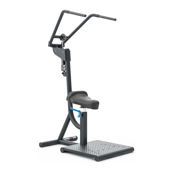
compass ® 210 Pulldown/Shoulder Press Handle Hydraulic resistance system Saddle Frame Ground mark On the one hand, this device can be used to train the shoulder blade-fixing muscles, which are necessary for a upright posture that is gentle on the spine is particularly important. In the second function, the muscles surrounding the neck are trained. -
Page 15: Compass ® 210 Chest Press/Rowing
compass ® 210 Chest Press/Rowing Handle Saddle Foot Hydraulic resistance system platform Frame On this machine, all dorsal muscle groups of the shoulder girdle, the arm flexor muscles and the back muscles in the area of the thoracic spine are trained during the rowing movement, which ensure that the spine is straightened. -
Page 16: Compass ® 210 Chest Press/Rowing Vertical
compass ® 210 Chest Press/Rowing Vertical Saddle Handle Foot platform Frame Hydraulic resistance system On this machine, the dorsal muscle groups of the shoulder girdle, the arm flexor muscles and the posture-stabilizing back muscles in the area of the thoracic and lumbar spine are trained in particular during the upward rowing movement. -
Page 17: Compass ® 210 Trunk Extension/ Flexion
compass ® 210 Trunk Extension/ Flexion Back cushion Cushion roll Handle Saddle Frame Hydraulic resistance system Ground mark This device trains both the dorsal and ventral trunk muscles. Specific patient positioning Adjust the saddle seat according to body height so that a semi-standing sitting position is achieved. Place the feet symmetrically using the ground marks. -
Page 18: Compass ® 210 Butterfly/ Butterfly Reverse
compass ® 210 Butterfly/ Butterfly Reverse Forearm pad Handl Saddl Foot Hydraulic resistance system platform Frame All muscle groups of the back and thoracic spine are trained on this device, which are necessary for the The spinal column is straightened and the shoulder joint is stabilized. Likewise, all Muscle groups responsible for the ventral stabilization of the shoulder girdle are trained. -
Page 19: Compass 210 Hip Extension Left
compass ® 210 Hip Extension left Hydraulic resistance system Forearm pad Hand Tread Frame Ground mark This machine trains the entire left hip extensor musculature. Specific patient positioning Place forearms symmetrically on the pad. Grasp the handles if necessary. Bend the standing leg slightly and align the foot parallel to the ground mark. -
Page 20: Compass ® 210 Hip Extension Right
compass ® 210 Hip Extension right Hydraulic resistance system Handl Forearm pad Tread Frame Ground marking This machine trains the entire right hip extensor musculature. Specific patient positioning Place forearms symmetrically on the pad. Grasp the handles if necessary. Bend the standing leg slightly and align the foot parallel to the ground mark. -
Page 21: Compass ® 210 Squat
3.10 compass ® 210 Squat Handle Shoulder pads Hydraulic resistance system Ground mark Frame The device enables functional training of the complete leg extension chain. Specific patient positioning Place the shoulders under the pads. Grasp handles firmly with wrists. Align the foot position symmetrically using the ground marks. -
Page 22: Hydraulic Resistance System
Hydraulic resistance system Attention: Do not operate the adjustment wheels (silver) for load adjustment during training or movement of the resistance system (damper)! The hydraulic resistance system is available with mechanical control. The resistance is adjusted via adjusting wheels with scaling attached to the piston. In this case, there are two wheels for adjusting the load in the case of bidirectionally acting devices and one wheel in the case of unidirectionally acting devices. -
Page 23: Technical Data On The Hydraulic Resistance Transducer
Representation of mechanical pistons Piston rod Filling valve Dial Technical data on the hydraulic resistance transducer Description Technical data Length (eye to eye) 370 - 393 mm Maximum stroke 190 mm Widest point 120 mm Eye width 16 mm Flap width min. 20 mm Maximum strength 10 kN... -
Page 24: Special Safety Instructions For The Hydraulic Resistance System
Wearing protective goggles is mandatory for maintenance work that is only to be carried out by • qualified personnel authorized by proxomed®. Due to the technical construction of the damper, spontaneous and explosive pressure reduction can occur during maintenance work. The filling pressure is 6 bar. -
Page 25: Details Of The Different Variants Of The Hydraulic Resistance System
Details of the different variants of the hydraulic resistance system Designation Description Resistance transmitter standard Resistance sensor variant for Ab/adduction, Butterfly/Butterfly reverse, Trunk extension/ flexion, Pulldown/Shoulder press, Chest press/rowing vertical. Resistance generator Chest press/Rowing Resistance transmitter variant for Chest press/Rowing. Special feature: Piston rod extension Resistance transmitter Squat/Hip extension... -
Page 26: Preparation
Preparation Transport The units are usually delivered fully assembled by our staff or by freight forwarder. The manufacturer is not liable for transport-related complaints, damage or missing parts which are not noted in writing on the delivery papers immediately upon delivery. Storage The storage location of the units should be dry, free of seawater and dust-protected and have a storage temperature between +5°C to +45°C. - Page 27 The following illustration clearly shows the space required for the individual versions (example illustration). A distance of min. 1m should be maintained between the movement range of the individual units. approx. approx. approx. Area up to next device Active approx. Training range (movement range) The illustration shows a possible compass arrangement of the device line.
-
Page 28: Commissioning
Commissioning Before commissioning, check the proper condition of the: ✓ Hydraulics for visible damage, especially to the respective end fastening. ✓ Check the function of the locking bolt, the locking button must engage automatically. ✓ Stability. ✓ Screw connections - check for tight connection. ✓... -
Page 29: Exercise Instructions
The training must not be performed as explosive strength training. The training shall be • performed at a steady moderate speed to avoid pressure peaks in the training system and on the exerciser. The intensity should be chosen to be emphatically light at the beginning of the training. The •... -
Page 30: Accessories
Accessories The following accessories can be attached to the unit: Article Designation Description 10667200 Climbing aid, foot platform The foot platform enables optimal use of the equipment by guaranteeing a firm footing for smaller users. If the ground cannot be reached when using the equipment, the use of the foot platform is recommended. -
Page 31: Technical Data
Technical data Dimensions / Transport Description Movement dimension dimensions Depth x width x height in Depth x width x height in Dimensions Abduction/Adduction 118 x 71 x 120 118 x 152 x 120 (art. 10667500) Pulldown/Shoulder press 123 x 71 x 153 123 x 71 x 227 (art. - Page 32 Max patient weight 200 kg Hip Extension right Max. Training weight Max. Unit weight 107 kg Max patient weight 200 kg Squat Max. Training weight Max. Unit weight 97 kg Ambient conditions Operation Temperature +5° to +45° Celsius Humidity <65% Transport and storage Temperature -20°...
-
Page 33: Maintenance
If, contrary to expectations, you notice any damage, stop the training immediately and inform the exercise instructor. In case of device problems which you cannot solve yourself in a simple way, please inform the proxomed service in any case. The authorized service will help you quickly and competently or provide ®... -
Page 34: Maintenance Instructions Of The Hydraulic Resistance Transmitter For The Operator
After cleaning, it is recommended to treat the sliding surface with suitable lubricants from the specialized trade. The suitable lubricants can be obtained from proxomed®. The damper must not be cleaned with aggressive cleaning agents. During cleaning work, make sure that the protective caps of the valves are screwed on. - Page 35 10.4 Cleaning Frame parts Clean the frame parts regularly with a damp cloth and mild soap to remove aggressive sweat residues. Handles, upholstery After training, please disinfect the grips and pads with disinfectant. list of appropriate disinfectants can be found at www.servicehelper.de.
- Page 36 11 Warranty This is based on the General Terms and Conditions of proxomed for warranty for defects, unless otherwise agreed. Our general terms and conditions of sale and payment (GTC) in their current version, can be viewed on our website.
- Page 37 Notes...
- Page 38 Changes: proxomed® reserves the right to change products if, in our opinion, these measures lead to an improvement in quality and function. All illustrations in these instructions for use are only approximate for typographical reasons; we accept no liability for typographical errors.
Need help?
Do you have a question about the compass 210 Abductor and is the answer not in the manual?
Questions and answers