Table of Contents
Advertisement
Quick Links
Advertisement
Table of Contents

Subscribe to Our Youtube Channel
Related Manuals for Metrohm Autolab RDE2


Summary of Contents for Metrohm Autolab RDE2
- Page 1 RDE2 User manual...
- Page 3 Utrecht, J.J.M. Coenen, QC Manager Metrohm Autolab B.V. at Utrecht will not accept any liability for damages caused directly or indirectly by connecting this instrument to devices, which do not meet relevant safety standards. The AUTOLAB RDE was developed as a laboratory research instrument.
- Page 4 The following safety practices are intended to ensure safe operation of the equipment. Not following these instructions when using the RDE motor controller may cause unsafe operation. Metrohm Autolab is not liable for any damage caused by not complying with the following instructions. Electrical Hazards ·...
- Page 5 GENERAL SPECIFICATIONS Power Supply (V) RDE Motor controller 100..240 V ± 10 % selectable in 4 ranges 100: 90..110 V 120: 108..132 V 220: 198..242 V 240: 216..264 V Power line frequency 50-60 Hz Power consumption 50 VA (max) Fuse (A-slow-slow) 100 V –...
-
Page 6: Table Of Contents
Table of Contents 1 – Description ....................1 2 – Installation of the motor controller .............. 1 3 – Powering the motor controller ..............2 4 – Installation of the RDE rotating mechanical unit ........... 2 4.1 – Mounting the electrode ............... 2 4.2 –... -
Page 7: Description
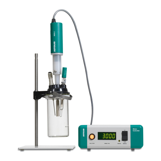
Autolab RDE User Manual 1 – Description The AUTOLAB RDE (Rotating Disc Electrode) consists of the rotating mechanical unit (RDE-2) and the motor control unit (MCUR) shown below in figure 1. Figure 1 – The Autolab RDE motor controller (MCUR, left) and the rotating mechanical unit (RDE-2) mounted on the electrochemical cell (right) 2 –... -
Page 8: Powering The Motor Controller
After unpacking, inspect the unit to make sure that there is no damage. The RDE contains a sealed rotating mercury contact. In case any damage is observed, contact your distributor or Metrohm Autolab immediately. 4.1 – Mounting the electrode Table 2 lists the electrode tips that can be used with the AUTOLAB RDE. - Page 9 Autolab RDE User Manual Figure 2 – Overview of the 5 mm tips compatible with the Autolab RDE To mount the electrode tip on the RDE shaft, press the shaft block button shown in Figure 3. This should lock the working electrode shaft. If the button cannot be engaged, rotate the shaft by hand, while pressing the locking button until it locks around the shaft.
-
Page 10: Connecting The Rde Rotating Mechanical Unit To The Motor Controller
Autolab RDE User Manual 4.2 – Connecting the RDE rotating mechanical unit to the motor controller Connect RDE-2 rotating mechanical unit to the controller unit via the circular multi-pole connector and mating chassis connector, labelled <MOTOR>, located on the rear panel of the controller shown in Figure 4. Connect also the BNC (2 m) cable to the <REMOTE INPUT>... - Page 11 Autolab RDE User Manual Connect the green ground cable from the AUTOLAB to the green receptor of the Y connector in order to shield the metallic housing of the rotating mechanical noise. Connect the Y cable to the top of the RDE-2 mechanical rotating unit (see Figure 6).
-
Page 12: Controlling The Rde
Autolab RDE User Manual Figure 7 – Correct position of the RDE in the cell 5 – Controlling the RDE The motor controller operates in 2 modes: Manual and Remote. 5.1 – Manual control mode To run the unit in Manual Mode, the <CONTROL MODE> switch on the rear panel should be in outermost <MANUAL>... -
Page 13: Viewing And Setting The Speed The Speed When The Motor Is Off
Autolab RDE User Manual can be altered either when the motor is running or when the motor is stopped. Please note that the manual speed setpoint is volatile, so a previously entered setpoint before the unit was switched off the mains cannot be recalled. 5.1.1 –... -
Page 14: Controlling The Rde With The Autolab
Autolab RDE User Manual Warning: To exclude any deviations in remote speed set points due to the load impedance of the controller’s remote input please respect the controller’s input impedance of 1MΩ ± 5%. 5.2.1 – Controlling the RDE with the Autolab Connect the DAC164 channel 1 or 2 in the front of the AUTOLAB (or the V the µAutolab) to the BNC connector on the rear panel of the motor controller, labelled <REMOTE INPUT>. - Page 15 Autolab RDE User Manual Figure 9 – The RDE control window The RDE control window can be used to control the rotation rate of the rotating mechanical unit. This can be done using the slider (from off to X RPM, where X is the maximum rotation rate defined in the RDE control Setup) or by typing a rotation rate in RPM or in Rad/s in the respective boxes in the RDE control window.
-
Page 16: Software Control In Nova
Autolab RDE User Manual Figure 10 – The RDE Setup Click <OK>. Set the motor controller on Run by toggling the Run/Stop switch. You can now control the speed of the RDE from the RDE control window. Note that the minimum RPM of the RDE is 100 rpm i.e. off in the RDE control window corresponds to 100 rpm. -
Page 17: Cleaning And Inspection
Autolab RDE User Manual Figure 11 – The control Autolab RDE and Switch Autolab RDE off commands can be found in the Measurement – general group of commands · Control Autolab RDE: this command can be used to set the rotation rate of the Autolab RDE to any value between 100 and 10000 RPM. -
Page 18: Changing And Polishing The Electrode Tip
WARNING: If the electrode cannot be removed by hand using the axis locking button, the unit must be returned to Metrohm Autolab for repair! Using excessive force on the axis may break the Hg contact. If the Hg contact leaks you will have trouble with future measurements. -
Page 19: Diagnostics
Autolab RDE User Manual Do not for any reason attempt to open the unit. There are no user serviceable parts. Failure to conform to user specifications described above may result in the void of any warranty claims. 9 – Diagnostics Problem: The controller does not seem to power up, after toggling the power switch (front speed display does not show any readings). -
Page 20: Limited Warranty
Please contact your Autolab distribitor or Metrohm Autolab if the rotator or the motor controller. The Autolab RDE rotating mechanical unit is intended to be used with Metrohm Autolab certified electrode tips only (see Table 2). Using uncertified tips will immediately void any warranty. - Page 22 7/2011 Kanaalweg 29/G 3526 KM Utrecht The Netherlands...
Need help?
Do you have a question about the Autolab RDE2 and is the answer not in the manual?
Questions and answers