Table of Contents
Advertisement
Quick Links
Advertisement
Table of Contents

Related Manuals for Metrohm MIRA XTR DS


Summary of Contents for Metrohm MIRA XTR DS
- Page 1 MIRA XTR DS 2.926.01XX Product manual 8.0926.8005EN / 2021-09-15...
- Page 3 Metrohm Raman 407 South 2nd Street Laramie, WY 82070 +1 307 460 2089 info@metrohm.com www.metrohm.com MIRA XTR DS 2.926.01XX Firmware version 8.0.3.40 or higher Product manual 8.0926.8005EN / 2021-09-15...
- Page 4 Technical Communication Metrohm Raman Laramie, WY 82070 This documentation has been prepared with great care. However, errors can never be entirely ruled out. Please send comments regarding possible errors to the address above. Copyright This documentation is protected by copyright. All rights reserved.
-
Page 5: Table Of Contents
Installing HazMasterG3 app for Android ......17 Installing MIRA Cal M for Android ........18 Energy supply ..............20 5.3.1 Energy supply with batteries ..........20 5.3.2 Energy supply with MIRA PowerPack ........23 USB connection ..............29 ■■■■■■■■ MIRA XTR DS... - Page 6 Cleaning the product surface ..........93 9 Disposal 10 Technical specifications 10.1 Ambient conditions ............96 10.2 Interfaces ................97 10.3 Energy Supply ..............97 10.4 Dimensions and materials ..........97 10.5 Operating specifications ............ 98 ■■■■■■■■ MIRA XTR DS...
-
Page 7: Overview
Barely larger than a smartphone, MIRA spectrometers are the only handheld Raman spectrom- eters currently on the market with Orbital Raster Scan (ORS) technology. Model versions MIRA XTR DS instruments are available in the following versions: Table 1 Model versions 2.926.0110... -
Page 8: Mira Software
MIRA software ■■■■■■■■■■■■■■■■■■■■■■ MIRA software MIRA Cal DS software In order to configure a MIRA DS or MIRA XTR DS instrument, the follow- ing software is needed: Table 2 Model versions 6.06071.020 MIRA Cal DS USB Stick To download the latest version of MIRA Cal DS software and firmware, click on the following link: https://www.metrohm.com/en/support-and-service/software-center/mira-... -
Page 9: About The Documentation
Metrohm Raman, Inc. To obtain such permission, or to obtain additional copies of this manual, please contact Metrohm Raman, Inc. - Page 10 Metrohm Raman, Inc. or its affiliates have been notified of the possibility of such damages.
-
Page 11: Additional Information - Software Tutorials
Accessories Up-to-date information on the scope of delivery and on optional accesso- ries can be found on the Metrohm website. Download this information as follows: Downloading the accessories list 1 Go to https://www.metrohm.com. 2 Enter the article number of the product (e.g. 2.1001.0010) into the search field. -
Page 12: Safety
■■■■■■■■■■■■■■■■■■■■■■ 2 Safety Intended use Metrohm products are used for the analysis and handling of chemicals and other materials. Usage therefore requires the user to have basic knowledge and experience in handling chemicals. Knowledge with respect to the application of the fire prevention measures prescribed for laboratories is also mandatory. -
Page 13: Personnel Requirement
Laser safety Nominal ocular hazard distance (NOHD) The following information refers to the nominal ocular hazard distance (NOHD) for MIRA DS and MIRA XTR DS instruments in accordance with EN 60825-1, "Safety of laser products", see "Operating specifications", page 98. - Page 14 Follow the provisions of the IEC 60825-1 standard "Safety of laser ■ products" and the regulations for the use of laser systems in your country. You can purchase protective laser glasses (6.7560.010) from Metrohm AG Accessories (see chapter 1.7, page 5). Laser classification depending on Smart Tips Attached Smart Tip...
-
Page 15: Warning Stickers On The Instrument
■■■■■■■■■■■■■■■■■■■■■■ Safety Attached Smart Tip Laser Class 1 Laser Class SERS Attachment Tablet Holder, Vial Holder and Calibration Standard have an interlock mechanism for measurement. This mechanism prevents laser radiation from emerging. The laser stops immediately if: The lid of the Smart Tip is opened. ■... - Page 16 Safety instructions ■■■■■■■■■■■■■■■■■■■■■■ Figure 1 Warning stickers on the left side and rear of the instrument Laser aperture sticker Laser classification sticker Emergence of laser Laser classification of the instrument: laser class 3B Invisible laser radiation Avoid exposure to beam Laser specifications Figure 2 Sticker at the bottom of the instrument...
-
Page 17: Warning Sticker On The Autofocus Stand-Off Attachment
■■■■■■■■■■■■■■■■■■■■■■ Safety Complies with Complies with IEC 60825-1:2014 21 CFR 1040.1 & 1040.11 except for deviations pursuant to Laser Notice No. 50, dated June 24, 2007 Serial number Manufacturing date: month / day / year 2.4.4 Warning sticker on the autofocus stand-off attachment Wavelength: 515 nm Class 2 Wavelength: 850 nm Class 1 Compliance information... -
Page 18: Meaning Of Warning Signs
Meaning of warning signs ■■■■■■■■■■■■■■■■■■■■■■ DANGER Type and source of danger Consequences when not observing the notice: An irreversible injury that may result in death is very probable. Measures to avoid the danger ■ WARNING Type or source of danger Consequences when not observing the notice: A serious injury that may result in death is probable. - Page 19 ■■■■■■■■■■■■■■■■■■■■■■ Safety Warning sign Meaning Warning of hot surface Warning of biological hazard Warning of toxic materials Warning of flammable materials Warning of corrosive substances Warning of optical radiation Warning of laser beams Depending on the intended use of the product, the corresponding warn- ing sign stickers must be placed on the product.
-
Page 20: Functional Description
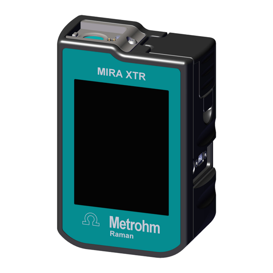
Overview of the instrument ■■■■■■■■■■■■■■■■■■■■■■ 3 Functional description Overview of the instrument Figure 3 MIRA XTR DS – Front Battery compartment Type B mini USB connector On/off switch Touch screen Magnetic smart tip fixture / laser aper- ture ■■■■■■■■... - Page 21 ■■■■■■■■■■■■■■■■■■■■■■ Functional description Figure 4 MIRA XTR DS – Rear Accessories covering Long Working Distance Attachment Lens (LWD) Storage Short Working Distance Attachment Type plate Lens (SWD) Storage ■■■■■■■■...
-
Page 22: Delivery And Storage
Delivery ■■■■■■■■■■■■■■■■■■■■■■ 4 Delivery and storage Delivery Inspect the delivery immediately upon receipt: Check the delivery against the delivery note to ensure completeness. ■ Check the product for damage. ■ If the delivery is incomplete or damaged, contact your regional Met- ■... -
Page 23: Installation
■■■■■■■■■■■■■■■■■■■■■■ Installation 5 Installation Installing HazMasterG3 app for Android The installation of HazMasterG3 is optional (6.6071.640). HazMasterG3 is a CBRNE/IED and HME investigative tool for use in tradi- tional incident response situations. It delivers insights and guidance for 167,000+ chemical agents (toxic industrial chemicals (TICs), toxic industrial materials (TIMs), chemical warfare agents (CWAs), precursors, trade names, etc.). -
Page 24: Installing Mira Cal M For Android
Installing MIRA Cal M for Android ■■■■■■■■■■■■■■■■■■■■■■ Installing MIRA Cal M for Android The installation of MIRA Cal M is optional. With MIRA Cal M you can conveniently store, manage and exchange data acquired on a MIRA instrument. The app allows not only to activate or deactivate purchased libraries, but also to transfer data between the MIRA instrument and MIRA Cal M. - Page 25 ■■■■■■■■■■■■■■■■■■■■■■ Installation Figure 5 MIRA Cal M home screen NOTICE When MIRA Cal M is launched, libraries are downloaded in the background. For a successful download, the app has to be open and the Android device has to be connected to the internet. This process can take a few minutes.
-
Page 26: Energy Supply
Energy supply ■■■■■■■■■■■■■■■■■■■■■■ Energy supply 5.3.1 Energy supply with batteries Battery indicator Charge status Full Almost full Half full Yellow battery warning We recommend to change the batteries when the battery indicator changes color from yellow to red. Red battery warning The instrument will give a low battery warning and then shut down. - Page 27 ■■■■■■■■■■■■■■■■■■■■■■ Installation NOTICE Battery type recommendation Use AA Energizer® Ultimate Lithium™ batteries. We also support rechargeable NiMH Panasonic eneloop pro™ batteries. Pull the lever. ■■■■■■■■...
- Page 28 Energy supply ■■■■■■■■■■■■■■■■■■■■■■ Open the top cover. Exchange batteries. Refer to the plus and minus signs on the hous- ing. ■■■■■■■■...
-
Page 29: Energy Supply With Mira Powerpack
■■■■■■■■■■■■■■■■■■■■■■ Installation Close the top cover. Push the top cover down until it latches closed. 5.3.2 Energy supply with MIRA PowerPack The optional MIRA PowerPack is a Li-Ion battery pack. The MIRA Power- Pack can be attached to power the instrument for up to 9 hours of opera- tion. - Page 30 Energy supply ■■■■■■■■■■■■■■■■■■■■■■ Figure 6 MIRA PowerPack – Front Charge indicator Check button 4 LED indicator lights show the state of The check button lights up the charge charge. indicator. Lock button USB Mini-B plug The lock button is used for mounting the The USB Mini-B plug connects the MIRA PowerPack on the instrument.
- Page 31 ■■■■■■■■■■■■■■■■■■■■■■ Installation Figure 7 MIRA PowerPack – Rear USB-C connector USB connector for charging the MIRA PowerPack. NOTICE Do not bend the cable. Charging instructions MIRA PowerPack is shipped at <25% charge, in accordance with IATA reg- ulations. Please charge MIRA PowerPack fully before first use. 1 Plug the power charger to the power grid and connect the USB-C plug to the MIRA PowerPack USB-C connector.
- Page 32 Energy supply ■■■■■■■■■■■■■■■■■■■■■■ The charge indicator will flash briefly while the MIRA PowerPack negotiates the charge voltage. After a few seconds, the charge indicator will display the current state of charge. Charging 0% - 25% 25% - 50% 50% - 75% 75% - 100% 100% Red lights progressing 1 - 4...
- Page 33 ■■■■■■■■■■■■■■■■■■■■■■ Installation Installing the MIRA PowerPack Remove the lanyard from the lanyard pins. Facing the front of MIRA DS and MIRA Pow- ■ erPack, hook the MIRA PowerPack's right latch onto the instrument's right lanyard pin. Press and hold the lock button. ■...
- Page 34 Energy supply ■■■■■■■■■■■■■■■■■■■■■■ Connect the USB Mini-B plug to the instru- ment. Checking the MIRA PowerPack state of charge 1 To check the state of charge, press the Check button The MIRA PowerPack charge indicator will light for approximately 3 seconds.
-
Page 35: Usb Connection
USB connection NOTICE We do not recommend to use third party USB cables, only use the provided Metrohm USB Mini-B cable (order number 6.215.1110). Energy supply For stationary use in the laboratory, you can operate the instrument with the USB interface which is connected to a powered USB hub. The USB hub also allows data transfer. - Page 36 Safe shutdown ■■■■■■■■■■■■■■■■■■■■■■ The on/off switch is pressed and held for 3 seconds or longer. ■ The battery door is opened while running on batteries only. ■ The USB is unplugged while running on USB only. ■ ■■■■■■■■...
-
Page 37: Initial Configuration
■■■■■■■■■■■■■■■■■■■■■■ Initial configuration 6 Initial configuration NOTICE Configuration Use MIRA Cal DS software to change instrument settings and to install spectral libraries. Refer to MIRA Cal DS software tutorial for detailed information (see "Additional Information – Software tutorials", page 5). ■■■■■■■■... -
Page 38: Operation And Control
The scope of delivery depends on the model version of the instrument (see "Model versions", page 1). You can purchase other attachments sep- arately from Metrohm AG (see "Accessories", page 5). The following Smart Tips are available: ■■■■■■■■... - Page 39 ■■■■■■■■■■■■■■■■■■■■■■ Operation and control Autofocus Stand-off Attachment Contact Ball-Probe (6.07506.030) (6.07506.070) The Contact Ball-Probe allows to collect data The Autofocus Stand-off Attachment allows from a substance with no concern of proper the collection of data from a distance of focus. Simply contact the substance with the 0.3 m to 2.0 m.
- Page 40 Smart Tips – Overview ■■■■■■■■■■■■■■■■■■■■■■ Stand-off Attachment (6.07506.020) Right Angle Attachment (6.07506.000) The Stand-off Attachment allows to collect The Right Angle Attachment allows the col- data from a distance of 0.25 m to 1.5 m. lection of data by placing the substance on a surface and laying the MIRA DS down next The Stand-off Attachment can be used to to the substance with the Right Angle...
- Page 41 ■■■■■■■■■■■■■■■■■■■■■■ Operation and control Extra Long Working Distance Attach- 10 SERS Attachment (6.07506.040) ment Lens (XLWD) (6.07505.020) The SERS Attachment accommodates propri- The extra long working distance attachment etary SERS substrates. lens is used for point and shoot measure- Class 3B laser operation. ments.
-
Page 42: Attaching Smart Tips
Attaching Smart Tips ■■■■■■■■■■■■■■■■■■■■■■ Attaching Smart Tips Using Calibration Standard Attach the Smart Tip by engaging the bottom left corner of the tip into the left edge of the mounting point. Rotate the tip into position. ■■■■■■■■... - Page 43 ■■■■■■■■■■■■■■■■■■■■■■ Operation and control Using Attachment Lenses WARNING Eye injury by laser radiation Laser radiation can cause serious eye injuries. Follow the safety measures and instructions. ■ Instruments must be used by trained personnel only. ■ Instruments of the laser class 3B must be used in protected and ■...
- Page 44 Attaching Smart Tips ■■■■■■■■■■■■■■■■■■■■■■ Using Universal Attachment WARNING Eye injury by laser radiation Laser radiation can cause serious eye injuries. Follow the safety measures and instructions. ■ Instruments must be used by trained personnel only. ■ Instruments of the laser class 3B must be used in protected and ■...
- Page 45 ■■■■■■■■■■■■■■■■■■■■■■ Operation and control Attach the Smart Tip by engaging the bottom left corner of the tip into the left edge of the mounting point. Rotate the tip into position. The Universal Attachment has 3 positions. Rotate the attachment to change the position. The dots indicate the position of the Universal Attachment.
- Page 46 Attaching Smart Tips ■■■■■■■■■■■■■■■■■■■■■■ Using intelligent Universal Attachment WARNING Eye injury by laser radiation Laser radiation can cause serious eye injuries. Follow the safety measures and instructions. ■ Instruments must be used by trained personnel only. ■ Instruments of the laser class 3B must be used in protected and ■...
- Page 47 ■■■■■■■■■■■■■■■■■■■■■■ Operation and control The intelligent Universal Attachment has 3 positions. Rotate the attachment to change the position. The dots indicate the position of the intelligent Universal Attachment. On screen messaging indicates each position use: 1 dot = Surface, 2 dots = Bag, 3 dots = Bottle.
- Page 48 Attaching Smart Tips ■■■■■■■■■■■■■■■■■■■■■■ Open the Vial Holder and insert a vial to meas- ure its contents. Using Right Angle Attachment WARNING Eye injury by laser radiation Laser radiation can cause serious eye injuries. Follow the safety measures and instructions. ■...
- Page 49 ■■■■■■■■■■■■■■■■■■■■■■ Operation and control Attach the Smart Tip by engaging the bottom left corner of the tip into the left edge of the mounting point. Rotate the tip into position. ■■■■■■■■...
- Page 50 Attaching Smart Tips ■■■■■■■■■■■■■■■■■■■■■■ Using Contact Ball-Probe WARNING Eye injury by laser radiation Laser radiation can cause serious eye injuries. Follow the safety measures and instructions. ■ Instruments must be used by trained personnel only. ■ Instruments of the laser class 3B must be used in protected and ■...
- Page 51 ■■■■■■■■■■■■■■■■■■■■■■ Operation and control Tighten using the brass knob on the attach- ment. Do not over tighten. Using Stand-off Attachment WARNING Eye injury by laser radiation Laser radiation can cause serious eye injuries. Follow the safety measures and instructions. ■ Instruments must be used by trained personnel only.
- Page 52 Attaching Smart Tips ■■■■■■■■■■■■■■■■■■■■■■ Attach the Smart Tip. Seat the brass knob into the recess on the left side of the instrument. Tighten using the brass knob on the attach- ment. Do not over tighten. ■■■■■■■■...
- Page 53 ■■■■■■■■■■■■■■■■■■■■■■ Operation and control Manually adjust the adjustment ring to the desired Stand-off distance and acquire the data. NOTICE It is recommended to use a tripod when using the stand-off attachment. Using Autofocus Stand-off Attachment WARNING Eye injury by laser radiation Laser radiation can cause serious eye injuries.
- Page 54 Attaching Smart Tips ■■■■■■■■■■■■■■■■■■■■■■ Attach the Smart Tip. Seat the brass knob into the recess on the left side of the instrument. Tighten using the brass knob on the attach- ment. Do not over tighten. NOTICE It is recommended to use a tripod when using the autofocus stand-off attachment.
- Page 55 ■■■■■■■■■■■■■■■■■■■■■■ Operation and control Using SERS Attachment WARNING Eye injury by laser radiation Laser radiation can cause serious eye injuries. Follow the safety measures and instructions. ■ Instruments must be used by trained personnel only. ■ Instruments of the laser class 3B must be used in protected and ■...
- Page 56 Attaching Smart Tips ■■■■■■■■■■■■■■■■■■■■■■ Attach the Smart Tip. Slide the SERS paper substrate, printed side down, into the slot on the side of the attach- ment. Insert the strip until resistance is met. The attachment accommodates the strip at the optimal depth.
- Page 57 ■■■■■■■■■■■■■■■■■■■■■■ Operation and control Remove the attachment from the instrument or power down the instrument. Open the hinged door of the attachment. Remove the strip. Wipe down interior surfaces with a kimwipe or swab. Use ethanol or isopropanol to clean the attachment.
-
Page 58: Acquiring Data
Acquiring data ■■■■■■■■■■■■■■■■■■■■■■ Open the Tablet Holder. Push the levers and position the sample in the middle. Release the levers to fix the sample. Acquiring data The following steps show how to acquire spectra with the instrument. NOTICE Default pincode of the instrument is 1234. Additional pin codes have to be defined and synchronized beforehand on MIRA Cal DS Soft- ware. - Page 59 ■■■■■■■■■■■■■■■■■■■■■■ Operation and control Enter 1234 (default pincode) or a user configured pin code. After the PIN code is entered a prompt screen for calibration will appear. 3 To calibrate the system, select [Calibrate Device] (see "Calibrating the instrument", page 74). To skip the calibration and move to the home screen, select [Skip].
- Page 60 Acquiring data ■■■■■■■■■■■■■■■■■■■■■■ MIRA XTR DS is designed to be used with the default procedure. If one wishes to build and use a user procedure, be aware that this might affect the performance of the MIRA XTR DS matching algo- rithms.
- Page 61 ■■■■■■■■■■■■■■■■■■■■■■ Operation and control 4 Measuring the sample Start the measurement with [Acquire]. The status screen will indicate the stage of the smart acquire. You can abort the acquisition only during the actual data collection. Once the matching starts, the process cannot be aborted. ■■■■■■■■...
- Page 62 Acquiring data ■■■■■■■■■■■■■■■■■■■■■■ If MIRA XTR DS detects fluorescence, the Raman eXTRaction screen automatically appears. Once the extraction is complete the data will be matched to the enabled libraries. ■■■■■■■■...
- Page 63 ■■■■■■■■■■■■■■■■■■■■■■ Operation and control When the measurement is finished, the result appears as specified in the operating procedure. 5 Examining the result The results are displayed in 2 tabs: Mixture and Identification. Select the different tabs to see the identification and mixture results. Note: Both tabs may be empty if no mixture or no identification is found.
- Page 64 Acquiring data ■■■■■■■■■■■■■■■■■■■■■■ 6 Measuring the next sample Select [Back] button to return to the Laser Ready display. Select [Acquire] to start the measurement. Identification screens Identification screen Color code Hazard level Green Safe Orange Caution Danger Blue No information Grey Inconclusive For example, because of a...
- Page 65 ■■■■■■■■■■■■■■■■■■■■■■ Operation and control Result Name After acquisition is complete, the color coded Result Name screen is shown automatically. Spectrum The spectrum button shows the spectrum of the current sample. It will be overlaid with a spectrum from the library if available. ■■■■■■■■...
-
Page 66: Acquiring Data With The Iua
Acquiring data with the iUA ■■■■■■■■■■■■■■■■■■■■■■ Select SAMPLE or LIBRARY above the spectral viewing window to hide the corresponding spectrum. Activate Baselined to see the unprocessed raw spectrum. Acquiring data with the iUA The following steps show how to acquire spectra with the intelligent Universal Attachment (iUA). - Page 67 ■■■■■■■■■■■■■■■■■■■■■■ Operation and control 2 Changing the operating procedure To optimize the identification of contents in polymer or glass contain- ers, select [Change Procedure] and load the Content ID operat- ing procedure. NOTICE In the following instructions we assume that the Content ID operating procedure is loaded.
- Page 68 Acquiring data with the iUA ■■■■■■■■■■■■■■■■■■■■■■ When the sample measurement is finished, the instrument is ready for the container measurement. 6 Measuring the container Follow the instruction on the display, e.g. Position Laser on Con- tainer. Start the measurement with [Acquire]. When the measurement is finished, the result appears as specified in the operating procedure.
-
Page 69: Acquiring Data With The Afso
■■■■■■■■■■■■■■■■■■■■■■ Operation and control 7 Examining the result The results are displayed in 2 tabs: Contents and Container. Select the different tabs to see the respective result. Contents result Container result Select the three dots in the upper right corner to see GHS data or the HQI. - Page 70 Acquiring data with the AFSO ■■■■■■■■■■■■■■■■■■■■■■ The [Aim Laser] toggle automatically appears on the top of the ■ Arm Laser screen. The selected operating procedure appears and can be changed by ■ the [Change Procedure] button. The laser is ready to be armed. ■...
- Page 71 ■■■■■■■■■■■■■■■■■■■■■■ Operation and control [Aim Laser] on: A class 2 green aiming laser helps to target the ■ sample. [Aim Laser] off: The aiming laser is shut off. ■ NOTICE The aiming laser is a 514 nm Class 2 laser. The device will automatically obtain a distance to the target and report it in the Acquire screen.
- Page 72 Acquiring data with the AFSO ■■■■■■■■■■■■■■■■■■■■■■ 4 Measuring the sample Start the measurement with [Acquire]. 5 Examining the result See "Acquiring data", page 52. ■■■■■■■■...
-
Page 73: Settings
■■■■■■■■■■■■■■■■■■■■■■ Operation and control Settings Brightness setting 1 Swipe the upper edge of the screen down. 2 Adjust the brightness in the popping down window. 3 Swipe up to close the brightness adjustment tool. Menubar In the Menubar, you can access several sections. Back to previous screen ■... - Page 74 Settings ■■■■■■■■■■■■■■■■■■■■■■ Figure 8 Settings menu The menu offers the following settings. [Procedures]: see "Operating Procedures menu", page 69 ■ [Calibrate Device]: see "Calibrating the instrument", page 74 ■ [View Libraries]: see "Viewing, enabling and disabling libraries", ■ page 76 [System Settings]: see "System Settings menu", page 76 ■...
-
Page 75: Operating Procedures Menu
■■■■■■■■■■■■■■■■■■■■■■ Operation and control FCC ID ■ MAC ID ■ 7.6.1 Operating Procedures menu The Operating Procedures menu opens with , then Procedures Figure 9 Operating Procedures menu The menu offers the following options. [View Procedures] and their parameters, delete procedures: see ■... - Page 76 Settings ■■■■■■■■■■■■■■■■■■■■■■ 2 To view the procedure settings, select the name of the corresponding procedure. To delete a procedure, select . Confirm with [Delete]. Building operating procedure NOTICE Procedures created on the instrument cannot be edited on the instru- ment or in MIRA Cal DS. , then Procedures ▶...
- Page 77 ■■■■■■■■■■■■■■■■■■■■■■ Operation and control 3 Scan Delay To set a delay before the start of a scan, enable Scan Delay and set the scan delay time. 4 Smart Acquire Either enable or disable Smart Acquire. Enabling Smart Acquire ■ Enabling Smart Acquire on a custom operating procedure will run samples through the smart acquire noise and fluorescence rejection routines before matching against the enabled libraries.
- Page 78 Settings ■■■■■■■■■■■■■■■■■■■■■■ Disabling Smart Acquire ■ Select [Next]. Define the Laser Power (1 - 5) and the number of Averages. Activate Auto Integration, or deactivate Auto Integration and set an Integration Time. Select [Next]. 5 Processing XTR Select the [Select Mode] button. ■■■■■■■■...
- Page 79 ■■■■■■■■■■■■■■■■■■■■■■ Operation and control Choose the XTR Mode and select [Next]. [Every Scan] will always process the data using XTR algorithm ■ regardless if fluorescence is detected or not. [Automatic] will automatically process the data using XTR algo- ■ rithm when fluorescence is detected. [Prompted] prompts the user if florescence is detected.
-
Page 80: Calibrating The Instrument
Calibrating the instrument NOTICE Instrument calibration can also be done in MIRA Cal DS software with a connected instrument. 1 Attach a Metrohm provided Calibration Standard (see "Attaching Smart Tips", page 36). Place the instrument upright. , then [Calibrate Device]. - Page 81 ■■■■■■■■■■■■■■■■■■■■■■ Operation and control 3 With the Calibration Standard attached and the instrument placed upright, select [Calibrate]. 4 Ensure that the calibration is successful. Once the calibration is complete, a screen with the system suitability test will indicate if the system passed or failed. 5 Select [Next].
-
Page 82: Viewing, Enabling And Disabling Libraries
Settings ■■■■■■■■■■■■■■■■■■■■■■ The home screen appears. 7.6.3 Viewing, enabling and disabling libraries Select , then [View Libraries]. Figure 10 View Libraries screen The instrument shows the installed libraries. 2 Enable or disable the libraries for matching. 3 To add libraries to the instrument, use the MIRA Cal DS Software. 7.6.4 System Settings menu , then [System Settings]. - Page 83 ■■■■■■■■■■■■■■■■■■■■■■ Operation and control Figure 11 System Settings menu The menu offers the following system settings: [Change Time/Date]: see "Change Time and Date", page 77 ■ [Transfer Data]: see "Transfer Data: Mount the instrument as Stor- ■ age Device", page 77, see "Transfer Data: Bluetooth ® wireless tech- nology", page 79 [Shutdown Delay ]: see "Shutdown Delay", page 86 ■...
- Page 84 Settings ■■■■■■■■■■■■■■■■■■■■■■ 2 Plug in the instrument to a Windows PC using the provided USB cable. Select [Mount as Storage Device]. The instrument will undergo a setup to install device drivers onto the Windows PC. NOTICE When connecting to a PC, a window pops up asking if you want to [Scan and Fix] or [Continue without Scanning].
- Page 85 ■■■■■■■■■■■■■■■■■■■■■■ Operation and control 4 Importing sample files into MIRA Cal DS For example, you can import sample files into MIRA Cal DS: Open MIRA Cal DS. ■ Select [Advanced]. ■ Select File ▶ Open ▶ Samples. ■ Navigate to the mounted Android device. Open scannumber. ■...
- Page 86 Settings ■■■■■■■■■■■■■■■■■■■■■■ Select [Enable Bluetooth]. The instrument indicates: Bluetooth Mode. 2 Pairing and connecting On the Android device, open MIRA Cal M. ■■■■■■■■...
- Page 87 ■■■■■■■■■■■■■■■■■■■■■■ Operation and control Select Discover. NOTICE The instrument will appear in the available devices with the model name followed by the serial number. Example: MIRA DS 192600200020300000 If no devices are detected, ensure that Bluetooth is enabled on the Android device. 3 On the Android device, select MIRA DS 1926xxxxxxxxxxxxxx.
- Page 88 Settings ■■■■■■■■■■■■■■■■■■■■■■ Enter the PIN code 9999. Select OK. The Android device is now connected to the instrument. The instru- ment is ready to transfer data or acquire a spectrum. ■■■■■■■■...
- Page 89 ■■■■■■■■■■■■■■■■■■■■■■ Operation and control 4 MIRA Cal M The DEVICE tab of MIRA Cal M allows changing of the procedure, editing of the acquisition state, and acquiring a spectrum. 5 Operating procedure The display shows the current procedure, e.g.: Default Procedure. The instrument is designed to be used with the default procedure.
- Page 90 Settings ■■■■■■■■■■■■■■■■■■■■■■ NOTICE The default procedure will match the scanned sample to all of the enabled libraries present on the instrument. The default pro- cedure enables smart acquire to automatically adjust laser power and integration time. NOTICE The SERS Attachment automatically enables a specialized SERS operating procedure.
- Page 91 ■■■■■■■■■■■■■■■■■■■■■■ Operation and control 7 Downloading data from the instrument In the home screen of MIRA Cal M, open the menu . ■ Select [Download Samples]. ■ Select the number of scans to download. ■ MIRA Cal M downloads the samples from the instrument. 8 Exporting data In MIRA Cal M, select Samples, , [Export].
- Page 92 Settings ■■■■■■■■■■■■■■■■■■■■■■ 9 Emailing data In MIRA Cal M, select Samples, , [Export]. ■ Choose the information to be shared. [Email]. ■ Choose the scans to be sent. Select the desired mail client or ■ messenger and send the files. 10 Disconnecting In MIRA Cal M, select Select [Disconnect Bluetooth].
- Page 93 1 Mount the instrument as Storage Device (see "Transfer Data: Mount the instrument as Storage Device", page 77). 2 Select the appropriate language pack from https://www.metrohm.com/en/support-and-service/software-center/ and download the file. 3 Save the file to your MIRA device folder. 4 Reboot the device.
- Page 94 Settings ■■■■■■■■■■■■■■■■■■■■■■ 5 Choose your preferred language. The instrument supports the following languages: English ■ German ■ French ■ Spanish ■ Portuguese ■ Chinese ■ Italian ■ Turkish ■ Czech ■ Hungarian ■ NOTICE English is always the top button. Only one language and English are supported on the device.
- Page 95 ■■■■■■■■■■■■■■■■■■■■■■ Operation and control Select the battery type: Lithium ■ NiMH ■ The change will be reflected by the text in the battery indicator. This setting is persistent. NOTICE We recommend to change the batteries when the battery indicator changes color from yellow to red. ■■■■■■■■...
-
Page 96: Viewing And Editing Samples In The Scan Log
Viewing and editing samples in the scan log ■■■■■■■■■■■■■■■■■■■■■■ Viewing and editing samples in the scan log 1 Accessing the scan log Select to view the saved spectra in the Scan Log. The samples are listed as color-coded buttons: Color code Hazard level Green Safe... - Page 97 ■■■■■■■■■■■■■■■■■■■■■■ Operation and control The sample menu appears as a list of buttons. 3 Run Mixture Select [Run Mixture] to run the mixture matching routine against all enabled libraries on the instrument. Match name and spectra can be viewed. 4 Reprocess A sample can be re-processed to match to a different enabled library.
-
Page 98: Safe Shutdown
Safe shutdown ■■■■■■■■■■■■■■■■■■■■■■ 7 View Sample Select [View sample] to view the spectrum, the match name and the CAS# of an acquired sample. 8 Back Select [Back] to go back to the Scan Log. Safe shutdown NOTICE To prevent unexpected behavior in the instrument, always perform a safe shutdown. -
Page 99: Maintenance
Protect live components (e.g. power supply unit, power cord, con- ■ nection sockets) against moisture. Always have maintenance work and repairs on electrical compo- ■ nents carried out by a regional Metrohm service representative. Prerequisite: The product is switched off and disconnected from the energy supply. ■ ■■■■■■■■... - Page 100 Cleaning the product surface ■■■■■■■■■■■■■■■■■■■■■■ Required accessories: Cleaning cloth (soft, lint-free) ■ Water or ethanol ■ 1 Clean the surface with a damp cloth. Remove persistent contamina- tion with ethanol. 2 Wipe the surface with a dry cloth. 3 Clean the connectors with a dry cloth. ■■■■■■■■...
-
Page 101: Disposal
■■■■■■■■■■■■■■■■■■■■■■ Disposal 9 Disposal Properly dispose of chemicals and of the product to reduce negative effects on the environment and public health. Local authorities, waste dis- posal companies or dealers provide more detailed information on disposal. Observe the WEEE EU directive (WEEE = Waste Electrical and Electronic Equipment) for the proper disposal of waste electronic equipment within the European Union. -
Page 102: Technical Specifications
Ambient conditions ■■■■■■■■■■■■■■■■■■■■■■ 10 Technical specifications 10.1 Ambient conditions MIRA DS and MIRA XTR DS Nominal function range –20 to +50 °C at max. 93% relative humidity, noncondens- Storage and Transport –20 to +70 °C at max. 93% relative humidity, noncondens-... -
Page 103: Interfaces
■■■■■■■■■■■■■■■■■■■■■■ Technical specifications 10.2 Interfaces USB connector Type A/B mini USB connector (USB 3.0) with the following functions: Power supply Data transmission with USB cable (6.2151.110) 10.3 Energy Supply Battery specifications 2 x 1.5 V, size AA up to 3.5 hours Nominal input voltage 5 V DC Power consumption... -
Page 104: Operating Specifications
Operating specifications ■■■■■■■■■■■■■■■■■■■■■■ Weight 705 g Material Housing Aluminum anodized Accessories covering Thermoplastic elastomers (TPE-E) IP Rating (according to EN 60529) IP67 Ruggedization MIL-STD-810G Method 514.6C-1, C-2, C-3 Category MIL-STD-810 Method 516.6 Procedure IV MIL-STD-810G Method 516.6 Procedure VI MIL-STD-810G Method 512.5 Procedure I IEC 60529 Dust 10.5... - Page 105 ■■■■■■■■■■■■■■■■■■■■■■ Technical specifications Beam divergence 2 degrees Temporal emission structure Detection technique Orbital Raster Scan (ORS™) to average over the sample Laser class according to EN 60825-1 Class 3B Protection Level of protective glasses D LB5775–795 nm (according to EN 207) NOHD –...
Need help?
Do you have a question about the MIRA XTR DS and is the answer not in the manual?
Questions and answers