Table of Contents
Advertisement
Quick Links
Advertisement
Table of Contents

Related Manuals for Skov Grow-Box


Summary of Contents for Skov Grow-Box
- Page 1 Grow-Box Technical User Guide 2022.04.26 • 604499...
- Page 3 Technical User Guide Product and Documentation Changes SKOV A/S reserves the right to modify this manual and the product described herein without prior notice. In case of doubt, please contact SKOV A/S. The date of change appears from the front and back pages.
-
Page 4: Table Of Contents
Mounting of air distribution plates ................20 3.13 Mounting of sensor....................25 3.13.1 Mounting of antenna pipe ....................27 3.14 Mounting of Grow-Box frame with net ..............28 3.15 Mounting of SKOV logo ..................31 INSTALLATION GUIDE .................. 32 Electrical connection ....................32 4.1.1 Cable plan .......................... 32 4.1.2... -
Page 5: Product Description
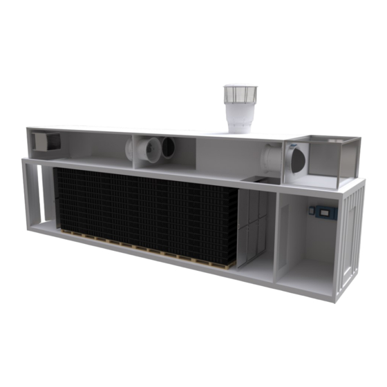
Technical User Guide 1 Product description Grow-Box is an insect container developed as a pilot concept for large-scale insect farming facilities with a focus on the black soldier fly (Hermetia illucens). It is thus intended for breeding and growth of larvae and pupae, but can be adapted to most types of insect farming systems, e.g. -
Page 6: Product Survey
Technical User Guide 2 Product survey 440010 Grow-Box 400V3 50Hz CN The insect container is used for insect farming. 4G modem CN 440011 Grow-Box 400V3 50Hz EU The insect container is used for insect farming. 4G modem EU Grow-Box... -
Page 7: Mounting Guide
A list of the recommended tools for mounting purposes can be seen below. Item Description Tape measure Marker pen Power drill Cordless drill Drill bits, various sizes Sealant gun Hammer Utility knife Hole saw kit Multimeter Pipe wrenches, various sizes Ladder Screwdriver Side cutter Pointed pliers Adjustable spanner Grow-Box... - Page 8 Technical User Guide Jigsaw Allen key Water pump pliers Spirit level Try square Grow-Box...
-
Page 9: Air Holes In The Roof Of The Container
Drill 4 pcs. 10 mm holes, one in each corner of the 2 markings. The plate with markings must be supported before the hole is sawn in order to avoid personal injury and damage to the container. Saw at the marking. Grow-Box... -
Page 10: Mounting Of Molding On Air Holes
Mounting of molding on air holes Measure up the air holes. Saw 4 moldings for both air holes. Apply MS mounting glue 292 white on the edges of the 2 air holes. Mount the 4 moldings in both holes. Grow-Box... -
Page 11: Mounting Of Extension Modules
230 mm Place extension module 1 on the container, see dimensions on the drawing. Extension module 1 Dismount transport bracket on extension module 2. Place extension module 2. Assemble the 2 extension modules with MS mounting glue 292. Grow-Box... -
Page 12: Mounting Of 5 M Cable
Mount angle steel on the inside. Mounting of 5 m cable Dismount 2 m cable on the 3 fan motors. Mount 5 m cable on the 3 fan motors according to Mounting Guide DA 600 LPC Cable Set. Grow-Box... -
Page 13: Mounting Of Fan Suspension
Technical User Guide Mounting of fan suspension Drill a 5.2 mm hole in the 16 supplied fan suspensions. Secure the 4 fan legs with a split pin at all 4 fans. Grow-Box... -
Page 14: Mounting Of Recirculation Fan
DA 74 200 mm mouth Bell mouth Saw up the bell mouth. Place the bell mouth so that the opening is facing downwards. Mount the bell mouth with screws in the wall and in the duct. Grow-Box... -
Page 15: Mounting Of Air Inlet
200 mm DA 74 mouth Bell mouth Saw up the bell mouth. Place the bell mouth so that the opening is facing downwards. Mount the bell mouth with screws in the wall and in the duct. Grow-Box... -
Page 16: Mounting Of Air Outlet
Mounting Guide DA 600 Chimney - Roof-Wall Exhaustion. Mount fan for air outlet according to Technical User Guide DA 600 LPC -3 fans. Adjust the roofing sheet so it is in line with the side of extension module 2. Grow-Box... -
Page 17: Mounting Of Cooling Pipe
Mount nozzles. Mount 2 high-pressure hoses on the cooling pipe. Mount high-pressure hose on the cooling pipe. Drill a 28 mm hole for the high-pressure hose between extension module 2 and extension module 1. Grow-Box... - Page 18 Technical User Guide End nozzle and drain plug valve Container doors Nozzles Mounting of cooling pipe at the container doors. Mount cooling pipe with end nozzle and drain plug valve. Mount nozzles. Mount high-pressure hose on the cooling pipe. Grow-Box...
-
Page 19: Water Supply For The Cooling Pump
Technical User Guide 3.11 Water supply for the cooling pump Cooling pump Water supply and water connection to the cooling pump must comply with the requirements in Technical User Guide DA 2000 high-pressure cooling. Grow-Box... -
Page 20: Mounting Of Air Distribution Plates
2 pcs. 2420 mm aluminum profiles. Fasten the 2 M8x25 mm screws with an Allen wrench through the holes in the 2 pcs. 2420 mm aluminum profiles. Mount molding on the 2 air distribution plates. Grow-Box... - Page 21 Mount the 2 air distribution plates. Place the last 2 pcs. 610 mm aluminum profiles at top and bottom. Fasten the 4 M8x25 mm screws with an Allen wrench through the holes in the 2 pcs. 2420 mm aluminum profiles. Grow-Box...
- Page 22 Mount 2 M8x80 mm threaded rods with washer and 2 nuts in the bottom of the air distribution plate. Mount the brush fillets on the side of the air distribution plate. Grow-Box...
- Page 23 Technical User Guide Place 4 hammer nuts in the aluminum profiles. Turn the hammer nuts so that they are fixed in the aluminum profiles. Mount the 2 handles using 4 M6x16 screws. Grow-Box...
- Page 24 Place the air distribution plate so it is in level. Mark up for the 6 holes in the bottom. Drill 6x12 mm holes in the bottom. Place the air distribution plates in the holes. Adjust the height of the air distribution plates by means of the 2 nuts. Grow-Box...
-
Page 25: Mounting Of Sensor
DOL 12 temperature sensor (placed in the insect crate) DOL 53 NH ammonia sensor Mount (A-3) DOL 114 humidity and temperature sensor, (B) DOL 119 CO sensor and (E) DOL 53 NH ammonia sensor on the bracket below the air outlet. Grow-Box... - Page 26 (B) DOL 119 CO sensor on the molding at the air inlet with bracket and cable tie. Mount (D) DOL 12 temperature sensor in or at the insect crates. Cable or sensor is lead through the roof of the container. Grow-Box...
-
Page 27: Mounting Of Antenna Pipe
Measure the distance between the 2 threaded rods. Mark up and drill 2x10 mm holes in extension module 2 closest to the technical room. Place antenna pipe on the outside. Mount the antenna pipe on the inside with washer and nut. Grow-Box... -
Page 28: Mounting Of Grow-Box Frame With Net
Technical User Guide 3.14 Mounting of Grow-Box frame with net Mount 8 M8x25 mm screws loosely at the ends of the 4 pcs. 1140 mm and 4 pcs. 1660 mm aluminum profiles. Grow-Box... - Page 29 Slide the the 2 hammer nuts onto 2 pcs. 1660 mm and 2 pcs. 2180 aluminum profiles. Slide the screws into the slot on the 4 pcs. 2180 mm aluminum profiles, so they form a rectangle as in the drawing. Grow-Box...
- Page 30 Place the hammer nuts as shown on the drawing. Mount 8 angles on the lower aluminum profiles with M6x12 screws. Mount the frame on the container using two 8 4.8x12 screws. Mount the fly net by pressing the edges down into the slots on the aluminum profiles. Grow-Box...
-
Page 31: Mounting Of Skov Logo
Technical User Guide 3.15 Mounting of SKOV logo Mount the SKOV logo on the side of the container as shown in the picture. Grow-Box... -
Page 32: Installation Guide
EN 60204-1 and any other EU regulations. The installation of a power supply isolator is required for each motor and power supply to facilitate voltage-free work on the electrical equipment. SKOV A/S does not supply the power supply isolator. -
Page 33: Connection Of Dol 119 Co Sensor
Connection of air outlet (DA 74) and with Dynamic Air sensor Terminals in DA 74 Signal type Conductor no. in cable for controller Open Close +24 V DC 0-10 V Conductor color in cable for sensor Dynamic Air sensor Brown +24 V DC White 0-10 V Black Blue Grow-Box... - Page 34 Technical User Guide Grow-Box...
- Page 36 SKOV A/S • Hedelund 4 • Glyngøre • DK-7870 Roslev Tel. +45 72 17 55 55 • Fax +45 72 17 59 59 • www.skov.com • Email: skov@skov.dk...
Need help?
Do you have a question about the Grow-Box and is the answer not in the manual?
Questions and answers