
Related Manuals for Tecsis E3907


Summary of Contents for Tecsis E3907
- Page 1 Pressure Temperature Switch Service Force Operating manual E3907 Universal handheld measuring device with datalogger...
- Page 2 Tecsis GmbH, Germany- 63073 Offenbach am Main Valid for E3907 handheld measuring device with datalogger Copyright © 2006 – 2015 tecsis GmbH, Offenbach, Germany Reproduction prohibited Reproduction, in whole or in part, only with written permission Change notice Subject to technical changes.
- Page 3 4.6.1 Transfer rate / specification RS232 (V.24) / USB 4.6.2 Operation via the serial interface 4.6.3 Handling with serial interface / USB 4.6.4 Operation and function principle of the E3907-Data Logger 4.7 Calibration ...................... 16 4.7.1 Calibrate the active sensor with control (ACT wCON) 4.7.2 Calibrate the active sensor without control (ACT nCON)
- Page 4 Operating manual E3907 BE 984 i www.tecsis.de...
-
Page 5: Safety Notes
Intended Purpose, Improper Usage A tecsis device is used for displaying, processing and controlling or regulation of processes. It shall not be used as the only tool for the prevention of dangerous states to machines and plants. Machines and plants must be constructed in such a way, that erroneous states cannot lead to a dangerous situation for the staff (e.g. - Page 6 - If parts of the device are loose or slack - If the connection cables show visible damages Furthermore, we point out that all obligations of tecsis exclusively result from the respective sales contract in which the guarantee has been conclusively settled.
-
Page 7: Qualified Personnel
The product may not be changed constructive without our. Any modification shall exclude our liability for any resulting damages. Repairs and modifications to the circuit boards are prohibited. 2. References The following documents contain reference information about the E3907 handheld measuring device: - AE 984.pdf, Datasheet of the E3907 www.tecsis.de... -
Page 8: Brief Description
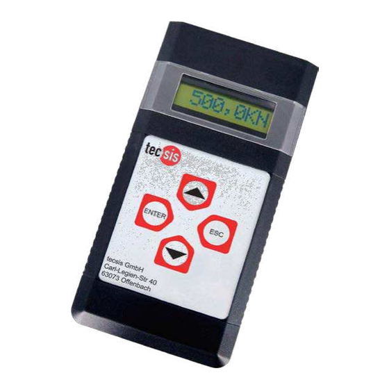
3.1 Brief description The E3907 is a DC measuring amplifier for passive or active sensors. A flexible data logger can store up to 3000 measured values with time and date. Mobile operation is possible by battery or accu operation, however, it can also be operated with a power unit. -
Page 9: Dimensions & Weight
Operating manual E3907 3.3 Safe and proper use Attention: - Protect the device from moisture, condensation, rain, snow... - Protect the device from direct sunlight - Protect the device from dust and dirt - Protect the device from high or excessive ambient temperature - Protect the device from excessive vibration. -
Page 10: Connection Description
Operating manual E3907 4. Instructions 4.1 Connection description Key assignment: ENTER: Switch on the device Confirm, one step forward in the menu ESC: Switch off the device Exit, one step back in the menu Scroll up Scroll down USB: USB-Socket for:... - Page 11 Operating manual E3907 www.tecsis.de BE 984 i...
- Page 12 Operating manual E3907 4.2 Switching on the device Press the ENTER button to switch on the device. 4.3 Menu description 4.3.1 Brief handling overview E3907 BE 984 i www.tecsis.de...
- Page 13 Operating manual E3907 4.3.2 Menu description 1 MEASURE Measuring mode SENSOR__ Sensor selection for measuring mode, sensor 0-9 Here the sensor parameter set for the measurement is being selected. The sensor parameter set must match the connected sensor. 2 SYSTEM All system parameters are being stored in this menu column.
- Page 14 MINUS the comma will be shifted. For the completion of the input press ENTER, thereafter the final value is being logged in the E3907 UNIT Input of the physical unit, e.g. Kg, Ncm, t, gr, kN, N•m, bar... DESIG Name of the sensor e.g.
-
Page 15: Serial Interface
4.6 Serial interface The E3907 handheld instrument uses for the serial data transfer either a RS232 or a USB interface. The USB interface is managed on the PC as a virtual COM port. For the use of the USB port, the PC must have a Windows operating system (2k, XP, Vista, 7) and it must be installed the USB drivers from tecsis. - Page 16 Operating manual E3907 4.6.2.1 Command overview ASCII Description 0x30 Query continuous measured value (signed integer) 0x31 Query maximal value (signed integer) 0x32 Query minimal value (signed integer) 0x33 Tare display 0x34 Reset maximal value 0x35 Reset minimal value 0x36 Actuate calibration control for sensors with 100 % control resistance...
- Page 17 0%load 2Byte HEX-value (MSB/LSB) 100% load 2Byte HEX- value (MSB/LSB) 4.6.2.3 Read out status: Status 2Byte, general error condition of the E3907 4.6.2.4 Read-Out complete status: Status 2Byte general error condition of the GM 80 0x01 … 1000/sec Measuring rate 1Byte 0x02 …...
- Page 18 4.6.2.8 Read Company Header With this command the company header, which is stored in the E3907, can be read. 4.6.2.9 Write all parameters The write-data block for all sensors is identical to the received read all parameters-data block. However for the writing of sensor parameters a checksum and the corresponding weighted checksum is required.
- Page 19 4.6.4 Operation and function principle of the E3907-Data Logger The data logger can, if the E3907 is not in the measuring mode, be read by the menu option 2,7 LOGG - SENDING or by the command "A" via the interface. Outside of the measuring mode the data logger is deleted only by the menu option 2,7 LOGG - DELETION.
- Page 20 Operating manual E3907 WINDOW: This mode reacts to increasing and/or decreasing flanks. At an increasing flank the logging of the measured values is started. From now on the measured values are written in the data logger with 1ms raster. A decreasing flank ends the recording LOGG OUT.
- Page 21 Depending on the setting, data can hereby either be logged or transferred as interface data output. This input has a high sampling rate and therefore are also very short pulses detected. 2 pol jack: Trigger 4.8.5 RS232 / USB: The E3907 uses for the serial data transfer either an RS232 or a USB interface. www.tecsis.de BE 984 i...
-
Page 22: Commissioning And Installation
Operating manual E3907 5. Product phases 5.1 Transport Notation: Please pack the devices suitable for the transportation. The device may not be movable in the packaging. Please protect the device from moisture. 5.2 Commissioning and installation Security measures before installation: Attention: The information for the voltage supply in section 5.2 must be respected. -
Page 23: Maintenance And Cleaning
The products contain no parts that need to be or that can be serviced by the user himself. Repairs may only be carried out by the tecsis GmbH. If it can be assumed that safe operation of the unit is no longer possible, it has to be put out of operation and secured against accidental operation. - Page 24 GmbH Carl-Legien-Straße 40-44 63073 Offenbach am Main Germany Phone: +49 69 5806-0 Fax: +49 69 5806-7788 E-Mail: force@tecsis.de Internet: www.tecsis.de...
Need help?
Do you have a question about the E3907 and is the answer not in the manual?
Questions and answers