
Related Manuals for Tecsis E1932


Summary of Contents for Tecsis E1932
- Page 1 Pressure Temperature Switch Service Force Reference Manual E1932 Weighing indicator...
-
Page 2: Table Of Contents
Reference Manual Rev 3.23 Software Versions 3.xx Table of Contents INTRODUCTION ........................4 1.1. Overview ........................4 1.2. Approvals ........................4 1.2.1. Trade versions ....................5 1.3. The Manuals Set ......................5 1.4. This Reference Manual ....................5 1.5. Document Conventions ....................5 SPECIFICATIONS ........................ - Page 3 Reference Manual Rev 3.23 Software Versions 3.xx 6.9.1. Full Setup Passcode ................... 28 6.9.2. Safe Setup Passcode ................. 28 6.9.3. Setup Lock-Out ................... 28 SETUP ............................ 29 7.1. Accessing Setup ......................29 7.1.1. Setup Display Prompts ................30 7.2. Exiting Full or Safe Setup .................... 30 7.3.
- Page 4 Reference Manual Rev 3.23 Software Versions 3.xx 12.3. R323 Dimensions ....................... 61 12.4. Setup Menu Quick Reference ..................63 12.5. Error Messages ......................65 12.5.1. Weighing Errors ..................65 12.5.2. Setup and Calibration Errors ............... 66 12.6. Diagnostic Errors ......................67 12.7.
-
Page 5: Introduction
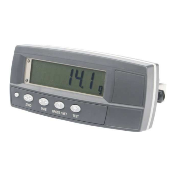
Reference Manual Rev 3.23 Software Versions 3.xx 1. Introduction This instrument is a precision digital indicator using the latest Sigma-Delta analogue to digital conversion technology to ensure fast and accurate weight readings. Figure 1: Weight Indicator The setup and calibration of the instrument are digital, with a non-volatile security store for all setup parameters. -
Page 6: Trade Versions
Reference Manual Rev 3.23 Software Versions 3.xx 1.2.1. Trade versions • • NSC approval (4000 divisions at 0.8µV/division). • NMI approval (4000 divisions at 0.8µV/division). NTEP approval (10000 divisions at 0.8µV/division). 1.3. The Manuals Set This manual is part of a set of manuals covering the setup and operation of the •... -
Page 7: Specifications
Reference Manual Rev 3.23 Software Versions 3.xx 2. Specifications Performance Resolution Up to 30,000 divisions, minimum of 0.25µV/division, (K303 up to 60,000 divisions) Zero Cancellation 2.0mV/V Span Adjustment 0.1mV/V to 3.0mV/V full scale Stability/Drift Zero: < 0.1µV/°C (+ 8ppm of deadload max) Span <... -
Page 8: Installation
Reference Manual Rev 3.23 Software Versions 3.xx 3. Installation 3.1. Introduction • Inspect indicator to ensure good condition. The following steps are required to set up the indicator. • Use connection diagrams to wire up load cell, power and auxiliary cables as •... -
Page 9: Cable Connections
Reference Manual Rev 3.23 Software Versions 3.xx 3.6. Cable Connections All cable connections are made to the rear of the instrument using screwless terminals. Wires must be stripped of insulation by at least 10mm. To install, depress the orange lever beside the terminal required and push wire into the hole. Release the lever and pull gently on the wire to ensure it is securely trapped in the terminal. -
Page 10: 4-Wire Connection
Reference Manual Rev 3.23 Software Versions 3.xx 3.8.2. 4-Wire Connection The minimum connectivity requirements are the connection of four wires (ie. Excitation + and – along with Signal + and –). Internally the instrument has a precision analogue switch that connects the Sense + and – lines directly to the Excitation + and –... -
Page 11: Auxiliary Connections
Reference Manual Rev 3.23 Software Versions 3.xx 3.9. Auxiliary Connections This section provides diagrams to illustrate the terminal connections. 3.9.1. RS-232 Serial Network: One Instrument to PC (RXD, TXD, GND) Figure 5: RS-232 – One Instrument to PC using COM Port (DB9) Figure 6: RS-232 –... - Page 12 Reference Manual Rev 3.23 Software Versions 3.xx Ring Networks: Multiple Instruments to PC (RXD, TXD, GND) Instruments can be configured in a Ring Network. The Short Ring Network layout can be used in situations up to a total cable run length of about 150 m (500 ft) at 9600 baud in a clean EMC environment.
- Page 13 Reference Manual Rev 3.23 Software Versions 3.xx Long Ring Network: Multiple Instruments to PC (RXD, TXD, GND) The Long Ring Network layout can be used in situations where each leg of the cable run can be up to about 150 m (500 ft) at 9600 baud. If there are communications errors, lower the baud rate to 4800 or 2400.
-
Page 14: Remote Input
Reference Manual Rev 3.23 Software Versions 3.xx Printer Connections (RXD/TXD, GND and DTR) Figure 9: RS-232 – Instrument to Printer (DB25) Remote Display (TXD, GND) The remote display documentation should be referred to for connection details. Connect TXD to RXD and GND to GND on the remote display. 3.9.2. -
Page 15: Outputs
Reference Manual Rev 3.23 Software Versions 3.xx 3.9.3. Outputs The output drivers for the instrument are isolated open emitter transistor drives that are capable of driving up to a total of 300mA. This configuration allows for the direct connection of the instrument outputs to most types of PLC. The voltage applied to the COM terminal appears on the output lines (ie. -
Page 16: Opto-Link (Optional)
Reference Manual Rev 3.23 Software Versions 3.xx 3.10. opto-LINK (Optional) A temporary infrared communications link can be established between the instrument and a PC using an optional opto-LINK cable. The optional opto-LINK cable can be used to transfer setup and calibration information from a PC (eg. to be stored for later use and/or transferred to other instruments). -
Page 17: Connecting Shields
Reference Manual Rev 3.23 Software Versions 3.xx 3.11. Connecting Shields To obtain full EMC or for RFI immunity, cable shields MUST be connected to the earth lug on the rear of the instrument. Figure 14 illustrates an example of possible connections. Also shown are the connecting cables restrained using cable ties fastened around the cable strain relief anchors. -
Page 18: Data Entry
Reference Manual Rev 3.23 Software Versions 3.xx 4. Data Entry Throughout the setup and normal weighing mode, different data entry methods are used. Each method is described below. When using the keypad for normal operation, press the key on keypad to initiate the feature. -
Page 19: Numeric Entry
Reference Manual Rev 3.23 Software Versions 3.xx 4.2. Numeric Entry A numeric entry box allows the input of a number. When entering a number, the display will show digits with the currently selected digit flashing. The <SEL> key is pressed to select a digit to change. When the digit is selected the <EDT> key is pressed to change the digit from 0 through 9. -
Page 20: Basic Operation
Reference Manual Rev 3.23 Software Versions 3.xx 5. Basic Operation In the most basic configuration, the instrument provides a simple weight readout. 5.1. Display and Controls Figure 16: Display and Controls Illustration 5.1.1. Front Panel: Visual Display The front panel has a six-digit LCD display. Figure 16 shows the main elements of the front panel. -
Page 21: Operation Keys
Reference Manual Rev 3.23 Software Versions 3.xx Status Annunciators Status annunciators show the following: Symbol Name Description Visible when the gross reading is within ± ¼ of a division of ZERO true zero. Visible when the displayed reading represents NET weight. Visible when the displayed reading is not stable. -
Page 22: Editing Function
Reference Manual Rev 3.23 Software Versions 3.xx installation. If a key has been locked, a long beep sounds when it is pressed. If however, the key beeps normally, but does not appear to trigger the desired action, it is waiting for the weight reading to settle before the action can proceed. 5.2.2. -
Page 23: Zero Key
Reference Manual Rev 3.23 Software Versions 3.xx 5.5. ZERO Key When an empty scale has drifted away from a true zero reading, this key is used to perform a zero adjustment on the scale display. The zero adjustment is stored when power is removed and is re-used when next powered up. -
Page 24: Gross/Net Key
Reference Manual Rev 3.23 Software Versions 3.xx 5.7. GROSS/NET Key This key toggles the weight display between the Gross weight and the Net weight (provided that a Tare has previously been acquired using the <TARE> key). 5.7.1. opto-LINK Activation This feature is used to temporarily connect a PC to the instrument for calibration and setup purposes. -
Page 25: Configuration Issues
Reference Manual Rev 3.23 Software Versions 3.xx 6. Configuration Issues 6.1. General Setup Information Configuration and calibration can be performed entirely from the front panel, using the digital setup facility. When Full Setup is used, all menu items are accessible and care must be taken to ensure no accidental changes are made to calibration and trade settings. -
Page 26: Dual Range Operation (K305 Only)
Reference Manual Rev 3.23 Software Versions 3.xx Calculating the total number of graduations: Signal voltages can be calculated as follows: Calculating the full scale signal (load cell): Since the instrument uses 5V load cell excitation, the absolute signal voltage is: Calculating the signal resolution: 6.3. -
Page 27: Gravity Compensation (K305 Only)
Reference Manual Rev 3.23 Software Versions 3.xx The number of graduations is selected to meet the requirements of both the loadcell and instrument. Calculating the Range 1 Full Scale (Choose the smaller number as result) Since Full Scale is less than Full Scale, Dual Range is enabled. Range1 For Range 1: (Signal voltages can be calculated as follows) Calculating the full... -
Page 28: Filtering Techniques
Reference Manual Rev 3.23 Software Versions 3.xx 6.6. Filtering Techniques There is a trade off between noise filtering and the step-response time of the system. The step-response is defined as the time between placing a weight on the scale and the correct stable weight reading being displayed. This does not affect the number of readings per second that are taken. -
Page 29: Passcodes
Reference Manual Rev 3.23 Software Versions 3.xx Industrial OIML NTEP The Calibration The Calibration The Calibration The Calibration Counter Counter Counter Counter increments when trade increments when increments when increments when critical settings in the marked with ⊗, are trade critical trade critical trade critical Calibration (CAL) menu,... -
Page 30: Setup
Reference Manual Rev 3.23 Software Versions 3.xx 7. Setup The instrument digital setup facilities provide the means to configure and calibrate the instrument. 7.1. Accessing Setup There are two methods to access the Setup area. For further details of menu items •... -
Page 31: Setup Display Prompts
Reference Manual Rev 3.23 Software Versions 3.xx 7.1.1. Setup Display Prompts When accessing Full or Safe Setup the instrument will beep twice and then display • FULL or SAFE (depending on setup access type) the following: • SETUP • Software Version (eg. V1.0) •... -
Page 32: Setup Menus
Reference Manual Rev 3.23 Software Versions 3.xx access to the items within the group. The <ITM> key can be used to cycle through the available items. The <SEL> key is then used to edit the item. 7.4. Setup Menus The following sections describe the setup parameters of each of the Groups and Items in Setup. -
Page 33: Option (Scale Options)
Reference Manual Rev 3.23 Software Versions 3.xx HI.RES (High Resolution x 10 mode) ⊗ Sets the instrument to display weight at 10 times resolution. This is intended for test purposes in trade applications but may be used for industrial weighing. This •... -
Page 34: Cal (Scale Calibration)
Reference Manual Rev 3.23 Software Versions 3.xx Z.TRAC (Zero Tracking Sensitivity) ⊗ Zero tracking allows the display to adjust for minor changes in the zero balance of the scale. When enabled, the instrument will track weight readings within the zero 'dead' band back to exactly zero at a maximum rate of 0.5 (SLOW) or 10 •... - Page 35 Reference Manual Rev 3.23 Software Versions 3.xx ED.LIN (Edit Linearisation Points) ⊗ (K302 Only) Select to view linearisation setup and start linearisation routines. While linearisation is in progress the display will show L.in P. Refer to ED.LIN (Edit Linearisation Points) page 45 for more information. CLR.LIN (Clear Linearisation Points) ⊗...
-
Page 36: Spec (Special Settings Menu)
Reference Manual Rev 3.23 Software Versions 3.xx 7.4.4. SPEC (Special Settings Menu) Settings within this group control features including passcodes, key locking, key functions and display settings. SAFE.PC (Safe Security Passcode for Digital Setup) The SAFE.PC (Safe Passcode) allows partial access to Digital Setup (ie. only non calibration/trade critical settings can be changed). - Page 37 Reference Manual Rev 3.23 Software Versions 3.xx is enough to keep the instrument powered on. When operating on batteries the instrument will turn off after 30 minutes of inactivity even if set to NEVER. • NEVER: Never power off automatically (Battery: powers down after 30 Options are: •...
-
Page 38: Serial (Serial Communications Options)
Reference Manual Rev 3.23 Software Versions 3.xx BAT.VLT (Battery Voltage) The indicator can be setup for a variety of different batteries. The low battery annunciator will display when the battery voltage drops below 1V per cell. For example, a 6 cell, 7.2V battery pack, has a low battery level of 6V. The indicator will assume it is on battery power when its input voltage is less than twice the low battery level for the selected battery voltage. -
Page 39: Set.pts (Setpoint Settings)
Reference Manual Rev 3.23 Software Versions 3.xx • N or O or E: Parity bit: (N) None, (O) Odd, (E) Even Options are: • 8, 7: Number of data bits • 1, 2: Number of stop bits • -, D: DTR handshake disabled or enabled •... -
Page 40: Clock (Clock Settings)
Reference Manual Rev 3.23 Software Versions 3.xx TARG.1 (Target for Output 1) This is the target value for output 1. This target provides the threshold value • Range: –99999 to 999999 when the OVER or UNDER type options are selected. •... -
Page 41: Test (Special Test Functions)
Reference Manual Rev 3.23 Software Versions 3.xx YEAR (Set Year) • Range: 2000 to 2099 MONTH (Set Month) • Range: 01 to 12 DAY (Set Day) • Range: 01 to 31 HOUR (Set Hour) • Range: 00 to 23 (24-hour format) MINUTE (Set Minute) •... -
Page 42: End - (Leaving Setup)
Reference Manual Rev 3.23 Software Versions 3.xx The instrument will prompt with Cont. N. Press <EDT> to change to Cont. Y and <OK> to continue. When Cont. Y has been chosen the instrument will display DONE to indicate that the operation has been completed. Restoring the factory options does not affect the calibration. -
Page 43: Calibration
Reference Manual Rev 3.23 Software Versions 3.xx 8. Calibration The calibration of the indicator is fully digital. The calibration results are stored in permanent memory for use each time the instrument is powered up. Note: Some of the digital setup steps can affect calibration. The BUILD and OPTION settings MUST be configured before calibration is attempted. -
Page 44: Zero (Zero Calibration Routine)
Reference Manual Rev 3.23 Software Versions 3.xx 8.1.1. ZERO (Zero Calibration Routine) Press the <SEL> key to start. The display will show the current weight. Remove all weight from the scale structure. Press <SEL>, <EDT> or <OK> to execute a Zero Calibration. The display will show Z.in.P to indicate that zeroing is in progress. -
Page 45: Dir.spn (Direct Span Calibration Entry)
Reference Manual Rev 3.23 Software Versions 3.xx 8.2.2. DIR.SPN (Direct Span Calibration Entry) Press the <OK> key to start. The display will show the current weight. Press the <OK> key to enter the Direct Span setting. Change the mV/V setting to the correct value for the full scale signal strength, using the <SEL>... -
Page 46: Ed.lin (Edit Linearisation Points) (K302 Only)
Reference Manual Rev 3.23 Software Versions 3.xx 8.3.1. ED.LIN (Edit Linearisation Points) (K302 only) Press the <SEL> key to step through the list of points. Each point is shown as Ln.ppp where n is the point number (1 to 10), and ppp is the approximate percentage of full scale where the linearisation is applied. - Page 47 Reference Manual Rev 3.23 Software Versions 3.xx 3. Set the G.FIRST setting to ON. This enables the user prompt. The scale can then be sent to the installation location. When the indicator is powered up the user will be prompted to enter the gravitational acceleration of their location (G.INST).
-
Page 48: Serial Outputs
Reference Manual Rev 3.23 Software Versions 3.xx 9. Serial Outputs The instrument can support the optional temporary opto-LINK connection. In addition, there is a single bi-directional RS-232 output. This provides a number of serial output types allowing communications with external devices such as printers, computers, PLCs or remote displays. -
Page 49: Printing
Reference Manual Rev 3.23 Software Versions 3.xx The Automatic Weight Output and Single Output types have several formats available • Format 1 including: • Format 2 • Master / Slave • Custom All serial output options are enabled and configured using the serial communications options in the digital setup procedure. - Page 50 Reference Manual Rev 3.23 Software Versions 3.xx • Standard Printing The instrument has a single fixed printing format that is as follows: 000048 06/05/2003 15:10 121.4 kg G 43.5 kg.N 77.9 kg T The first line contains a six digit sequential number that is automatically incremented with each printing, up to a maximum of 999999.
-
Page 51: Programmable Printing
Reference Manual Rev 3.23 Software Versions 3.xx If counting is active each of the individual printouts would have a third line as discussed above and the TOTAL would have an additional QTY line as follows: 000054 06/05/2003 15:22 13.3 kg G 000055 06/05/2003 15:23 79.3 kg G 000056 06/05/2003 15:23... -
Page 52: Master Serial Output
Reference Manual Rev 3.23 Software Versions 3.xx For example the following data loaded: \D9 at \C0 on \BF\0D\0A Would produce the printout below: 523 kg G at 09:18 on 10/08/2006<CR><LF> The menu selection FACTRY:DEFLT is used to clear the programmed printing and revert to the standard printing format. -
Page 53: Setpoints
Reference Manual Rev 3.23 Software Versions 3.xx 10. Setpoints The instrument is capable of working with two internal setpoints. The status of these setpoints is displayed on the LCD. Each setpoint is associated with a physical output driver but it may also be simply used as an indicator. Refer to SET.PTS (Setpoint Settings) page 38 for details on settings. -
Page 54: Special Functions
Reference Manual Rev 3.23 Software Versions 3.xx 11. Special Functions 11.1. Introduction The instrument has a special function key on the front panel. This function of this key can be configured to any of the key functions detailed below. Refer to KEY.FN (Key Functions) page 35 to configure the function key. -
Page 55: Hold And Peak Hold
Reference Manual Rev 3.23 Software Versions 3.xx 11.2.5. HOLD and PEAK HOLD The <HOLD> key implements a manual Hold function. The <PEAK> key implements a Peak Hold function where the largest absolute weight, either positive or negative is stored in the peak value (eg. -30 is larger than 25). The Hold annunciator is active when the display is showing the held weight. -
Page 56: Show.t
Reference Manual Rev 3.23 Software Versions 3.xx 11.2.7. SHOW.T The SHOW.T item stands for Show Total. The function key will be labelled <TOTAL>. The PRINT key is used not only to print the current weight but also to add that weight to the current total. -
Page 57: Set.pt
Reference Manual Rev 3.23 Software Versions 3.xx When the gross weight is stable within the zero 'dead' band the instrument will automatically zero and the gross weight of zero will be displayed. The next box can be placed on the scale and the process repeated. 11.2.10. -
Page 58: Appendix
Reference Manual Rev 3.23 Software Versions 3.xx 12. Appendix 12.1. R320 Dimensions Weight Indicator Dimensions in mm (1 inch = 25.4 mm) 3D View Front View Side View Back View Weight Indicator (Desk Mount with Battery Compartment) Dimensions in mm (1 inch = 25.4 mm) 3D View Front View Side View... - Page 59 Reference Manual Rev 3.23 Software Versions 3.xx Weight Indicator (IP65 rear boot) Dimensions in mm (1 inch = 25.4 mm) 3D View Front View Side View Back View Bottom View Page 58...
- Page 60 Reference Manual Rev 3.23 Software Versions 3.xx Weight Indicator (Hanging Scale) 3D View Front View 6.5in 166mm Side View Top View 6.3in 161mm Page 59...
-
Page 61: Sealing Details
Reference Manual Rev 3.23 Software Versions 3.xx 12.2. Sealing Details Affix sealing stickers to the rear of the instrument, over one or more screws in the locations indicated. Also affix a sealing sticker over the load cell cable where the cable-tie strain relief is attached, as indicated. Affix stickers in the locations indicated. -
Page 62: R323 Dimensions
Reference Manual Rev 3.23 Software Versions 3.xx 12.3. R323 Dimensions Weight Indicator (Desk Mounted) Dimensions in mm (1 inch = 25.4 mm) Desk Mounted 3D View Front View Side View Bottom View Weight Indicator (Panel Mounted) Dimensions in mm (1 inch = 25.4 mm) Panel Mounted 3D View Front View Rear View... - Page 63 Reference Manual Rev 3.23 Software Versions 3.xx Weight Indicator (Wall Mounted) Dimensions in mm (1 inch = 25.4 mm) Wall Mounted 3D View Front View Side View Back View Page 62...
-
Page 64: Setup Menu Quick Reference
Reference Manual Rev 3.23 Software Versions 3.xx 12.4. Setup Menu Quick Reference Note: ⊗ Available only in Full Setup. Changing this setting will increment the Calibration Counter. ⊗ 1 Available only in Full Setup. Changing this setting will not increment the Calibration Counter. Group (GRP) Item (ITM) Page... - Page 65 Reference Manual Rev 3.23 Software Versions 3.xx ⊗ Group (GRP) Item (ITM) Page DAY (Set Day) HOUR (Set Hour) MINUTE (Set Minute) SCALE (Scale Base Test Display) TEST FRC.OUT (Force Outputs) O.LOAD (Overload Count) CLR.OLD (Clear Overload) DEFLT (Restore Factory Settings Except for Calibration and FACTRY Build) - END -...
-
Page 66: Error Messages
Reference Manual Rev 3.23 Software Versions 3.xx 12.5. Error Messages A number of error messages may be displayed to warn of operation outside of the acceptable limits. These messages are described below. Short messages (XXXXX) will appear as a single message on the display. Longer messages (XXXXX) (YYYYY) will appear on the display in two parts, first the (XXXXX) part, then the (YYYYY) part. -
Page 67: Setup And Calibration Errors
Reference Manual Rev 3.23 Software Versions 3.xx 12.5.2. Setup and Calibration Errors These messages show status messages or errors that may occur during the instrument setup and calibration. Error Description Resolution (ENTRY) The instrument may be in Safe Access Full Setup to edit the item. (DENIED) Setup and an item that needs Full Setup has been selected for... -
Page 68: Diagnostic Errors
Reference Manual Rev 3.23 Software Versions 3.xx 12.6. Diagnostic Errors The instrument continually monitors the condition of the internal circuits. Any faults or out-of-tolerance conditions are shown on the display as an E type error message. • Check: This item can be checked on site by service personnel. In the table below the following terms are used: •... -
Page 69: Glossary Terms
Reference Manual Rev 3.23 Software Versions 3.xx 12.7. Glossary Terms Term Definition The communications protocol used to communicate with the R300 Series COMM Count-by The smallest change in weight units that the display can show. See also Resolution. Division A single graduation. EEPROM Electrically Erasable Programmable Read-Only Memory Electro-Magnetic Compatibility Regulation... -
Page 70: Index
Reference Manual Rev 3.23 Software Versions 3.xx 13. Index Editing Annunciators, KEY.FN, 35, 53, 63 SCALE (Scale Base 17, 21 KEY.LOC, 35 Test Display), 40 4-Wire Connection, 9 Electrical Safety, 7 Keypad Scale Build, 8, 33 EMC Immunity, 7 Sealing Details, 60 Normal 6-Wire Connection, 9 End –... - Page 71 Reference Manual Rev 3.23 Software Versions 3.xx Notes: Page 70...
- Page 72 GmbH Carl-Legien-Straße 40-44 63073 Offenbach am Main Germany Tel.: +49 69 5806-0 Fax: +49 69 5806-7788 E-Mail: info@tecsis.de Internet: www.tecsis.de...
Need help?
Do you have a question about the E1932 and is the answer not in the manual?
Questions and answers