Table of Contents
Advertisement
Quick Links
Advertisement
Table of Contents

Related Manuals for Spartus Multi Pro 200 4in1


Summary of Contents for Spartus Multi Pro 200 4in1
- Page 1 SPARTUS® Multi Pro 200 4in1 User’s manual...
- Page 2 Therefore, our offer covers such a wide assortment of products. Thank you very much for your trust in our company. We would like to invite you to familiarize yourself with the remaining products and offer at www.spartus. info or directly at a local distributor of SPARTUS® products.
-
Page 3: Table Of Contents
TABLE OF CONTENTS 1. SAFE USE – HAZARDS ASSOCIATED WITH ARC WELDING AND PLASMA CUTTING ....2 1.1 General safety rules ................................... 2 1.2 Electric shock can kill ................................2 1.3 Welding arc radiation can be dangerous ......................... 3 1.4 Vapours and gases can be dangerous ..........................3 1.5 Noise can be harmful ................................ -
Page 4: Safe Use - Hazards Associated With Arc Welding And Plasma Cutting
USER’S MANUAL 1. SAFE USE – HAZARDS ASSOCIATED WITH ARC WELDING AND PLASMA CUTTING Arc welding and plasma cutting are processes feeder fitted with spool and harness). Care that can pose hazards for the operator and per- shall be taken during manual handling. sons in his vicinity. -
Page 5: Welding Arc Radiation Can Be Dangerous
USER’S MANUAL • Power supply must never be connected Such radiation can be direct or reflected from before the accessories of SK sockets/con- surfaces such as bright metals and light colo- nectors are properly installed in the device. ured objects. •... -
Page 6: Noise Can Be Harmful
USER’S MANUAL Arc welding and allied processes produce wel- in case of an emergency, are in the imme- ding fume which may pollute the atmosphere diate vicinity. surrounding the work. Welding fume is a vary- • In closed rooms or in certain circumstances ing mixture of airborne gases and fine particles during outdoor operations, it may be re- which, if inhaled or swallowed, constitute a... -
Page 7: Fire Or Explosion Hazard
USER’S MANUAL source, observed for an adequate period after its c) effective maintenance of sound protection termination. devices, • „Hot spots” and immediate surroundings d) indication as „ear protection areas” where should be observed until their temperature applicable, has dropped to normal. e) restriction of entry to these „ear protection 1.6.2 Explosion hazard areas”... -
Page 8: Other Hazards
USER’S MANUAL 1.7.4 Moving elements can be dangerous cylinder valve socket when the valve is being opened. • Special valve shield should always be in- stalled during cylinder transportation or when the cylinder is not used. OTHER HAZARDS Arc welding and allied processes carrying other All protective elements and device housing hazards not listed before. -
Page 9: Symbols Used In Instructions
USER’S MANUAL WARNING The maximum voltage of 15kV. Accidental pressing of the microswitch results in unintentional arc ignition. Never bring a bare hand close to the electrode, when the device is connected to a power source. 1.9 SYMBOLS USED IN INSTRUCTIONS We use this symbol to pay your attention about important information. -
Page 10: Assesment Of Area
Methods of reducing electromagnetic interference are listed in detail in the standard EN 60974-9 – „Arc welding equipment – Part 9: Installation and use”. 4. CONFORMITY WITH STANDARDS SPARTUS® Multi Pro 200 4in1 is in conformity with the relevant Union harmonization legislation: LVD 2014/35/UE Low Voltage Directive... -
Page 11: General Description
Spool Gun. TIG welding Thanks to the solutions used, the Multi Pro 200 4in1 also enables advanced TIG AC and TIG DC welding with a choice of arc ignition HF or Lift method. The device is equipped with a pulse welding function, which makes the machine perfect for welding very thin sheets and aluminum. -
Page 12: Purpose Of Use
USER’S MANUAL 5.1 PURPOSE OF USE SPARTUS® Multi Pro 200 4in1 welding devices are designed for: • Metal Inert Gas welding (MIG) or Metal Active Gas welding (MAG), • Tungsten Inert Gas welding (TIG), • Manual Metal Arc welding (MMA). - Page 13 USER’S MANUAL MIG PARAMETERS Wire feeder built-in, 2-roll gear Wire diameter Ø [mm] 0.6 / 0.8 / 1.0 Welding wire spool ≤ 5[kg], ø200 Inductance control Wire feeding test 2T / 4T control Spool Gun Synergic ...
-
Page 14: Installation And Use
606 x 217 x 404 7. INSTALLATION AND USE WARNING! SPARTUS® Multi Pro 200 4in1 machines are intended for professional and industrial applications. Installation and use of the device may only be carried out appropriately trained professionals. It is forbidden to grinding and/or carrying out other locksmith works or mechanical working of metal in the vicinity of the ventilation opening of unit. -
Page 15: Description Of Construction
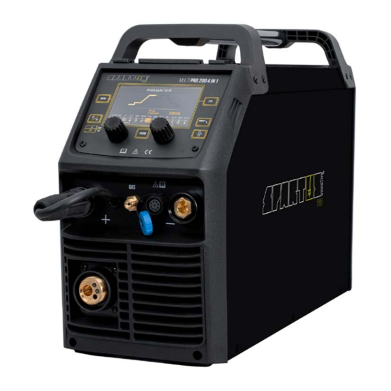
USER’S MANUAL 7.3 DESCRIPTION OF CONSTRUCTION 7.3.1 Welding source Control panel TIG torch gas connector SK „+” socket EURO socket – MIG gun connector SK „-” socket Toggle switch ON/OFF Gas connector for TIG Gas connector Polarity change power connection Power cable Spool holder Wire feed tension... -
Page 16: Connecting To Power Supply
USER’S MANUAL 7.4 CONNECTING TO POWER SUPPLY Requirements for power network parameters (voltage, permissible range of mains voltage fluctuations etc.) are given in the table with technical parameters of device and on the rating plate of welding machine. Before connecting the unit to the power source: •... - Page 17 USER’S MANUAL 7.5.3 MIG/MAG gun installation 1. Connect properly MIG gun plug to EURO socket 7 . 2. Pay special attention to the correct fit of the control pins and input welding wire from wire feeder to the wire inlet guide in MIG gun. 3.
- Page 18 USER’S MANUAL Pressure regulator Gas heater connection Power cable Gas cylinder Polarity change power connection cable Weld material MIG/MAG gun Work cable Control cable 7.5.6 Installation & operation for SPOOL GUN 1. Insert the earth cable plug into the SK „-” socket 2 on the front of the machine and twist to tighten.
-
Page 19: Installation - Mma Welding
USER’S MANUAL 9. Place a spool of wire inside the spool holder on post. 10. Feed the wire through the drive rolls and into the inlet guide tube. Tighten the wire ten- sion swing arm. 11. Pull the trigger to drive the wire down the neck until it exits the contact tip. 12. -
Page 20: Installation - Tig Welding
USER’S MANUAL 1. Connect electrode cable plug into SK socket 2 or 3 . 2. Connect return cable plug into appropriate SK socket 2 or 3 . 3. Connect earth clamp into workpiece. 4. Connect the welder into power supply in accordance with appropriate guidelines (see 7.4). 5. -
Page 21: Device Control Panel - Using
USER’S MANUAL 7.7.3 Connecting the device 1. Connect the gas pipe to the device (see 7.7.1). 3. Connect the welding holders TIG (see 7.7.2). 4. Connect the return line to the SK socket „+” 2 , and the mass clamp to the welded element. 5. - Page 22 USER’S MANUAL Gas test button Welding adjustment knob 1 Button for inserting the welding Welding adjustment knob 2 wire into the MIG gun Function button 7.8.1 Detailed description of selected buttons on the panel A WELDING MODE BUTTON: • MIG Synergic •...
- Page 23 USER’S MANUAL A WELDING MODE BUTTON H WELDING ADJUSTMENT KNOB 1: welding current I WELDING ADJUSTMENT KNOB 2: Hot Start or Arc Force TIG HF/LIFT DISPLAY INTRODUCTION A WELDING MODE BUTTON B 2T/4T TRIGGER MODE BUTTON G FUNCTION BUTTON: press it to enter the function interface H WELDING ADJUSTMENT KNOB 1: welding current I WELDING ADJUSTMENT KNOB 2: balance, AC frequency FUNCTION INTERFACE –...
- Page 24 USER’S MANUAL 1. Output waveform: Press it to select DC output or AC wave output. (AC wave forms: squa- re, sinusoidal, triangular) 2. PULSE mode: ON or OFF. 3. Trigger mode: 2T/4T/Spot weld (Spot is only available in TIG HF welding mode). 4.
- Page 25 USER’S MANUAL Press the gun switch and hold it. Electromagnetic gas valve is turned on. The shielding gas stars to flow. Pre-gas time. Initiation of the welding arc. Arc is ignited and the output current rises to the setting welding current from the min.
- Page 26 USER’S MANUAL FUNCTION INTERFACE – Spot weld 1. Post Gas: 0.1~2s. 2. Welding current: 10~200A. 3. T time: 0.2~1s. 4. T time: 0~10s. 5. Post Gas: 0.1~10s. SPOT weld trigger mode Gun Switch Gas Supply Wire Feed Output Voltage Output Current SPOT Weld Time...
- Page 27 USER’S MANUAL MIG MANUAL DISPLAY INTRODUCTION A WELDING MODE BUTTON B 2T/4T TRIGGER MODE BUTTON G FUNCTION BUTTON: press it to enter the function interface H WELDING ADJUSTMENT KNOB 1: wire feeding speed I WELDING ADJUSTMENT KNOB 2: welding voltage or inductance E GAS TEST BUTTON F BUTTON FOR INSERTING THE WELDING WIRE INTO THE MIG GUN FUNCTION INTERFACE –...
- Page 28 USER’S MANUAL 1. Trigger mode: 2T lub 4T 2. Burnback: 0~10 3. Pre Gas: 0.1~10s. 4. Post Gas: 0.1~10s. 5. Slow Feed: 0~10s 6. Spool Gun: on/off MIG SYNERGY DISPLAY INTRODUCTION A WELDING MODE BUTTON B 2T/4T TRIGGER MODE BUTTON D SYNERGY PROGRAMS BUTTON E GAS TEST BUTTON F BUTTON FOR INSERTING THE WELDING WIRE INTO THE MIG GUN...
- Page 29 USER’S MANUAL INTERFEJS FUNKCYJNY – for MIG Synergy 1. Trigger mode: 2T or 4T 2. Burnback: 0~10 3. Pre Gas: 0.1~10s. 4. Post Gas: 0.1~10s. 5. Slow Feed: 0~10s JOB DISPLAY INTRODUCTION...
-
Page 30: Remote Control
USER’S MANUAL Save / activate / delete memory channels on the device The device has 10 memory channels on which you can save the most-used machine settings. After selecting the appropriate parameters, press the button C for 1s (see 7.8.1). The settings will be saved to the first free channel. -
Page 31: Environmental Protection
10. TROUBLESHOOTING Not all problems with functioning of the device, are the evidence of failure. You can independently carry out an analysis in search of probable failure. In case of doubt, please contact to SPARTUS® dealer or authorized service center. - Page 32 USER’S MANUAL MIG WELDING PROBLEMS Voltage or wire feed speed set too high. Wrong polarity set. Excessive spatter. Stick out too long. Contaminated base metal or wire. Inadequate gas flow. Wrong gas or inadequate gas flow. Moisture on the base metal or wire. Porosity –...
- Page 33 USER’S MANUAL TIG WELDING PROBLEMS Incorrect gas or no gas. Inadequate gas flow. Tungsten burning away quickly. Back cap not fitted correctly. Incorrect tungsten being used. Wrong gas, poor gas flow, gas leak. Porosity - poor weld appearance and color. Contaminated base metal or wire.
- Page 34 Notes...
- Page 35 A masterly combination of high quality production, excellent parameters and ergonomics – these are fea- tures of the SPARTUS® Master series of devices, which were created with demanding welding jobs in mind. Precision, functionality, excellent parameters and resistance to high workloads –...
- Page 36 Videopresentation of products Subscribe to the channel SPARTUS.INFO...
Need help?
Do you have a question about the Multi Pro 200 4in1 and is the answer not in the manual?
Questions and answers