Table of Contents
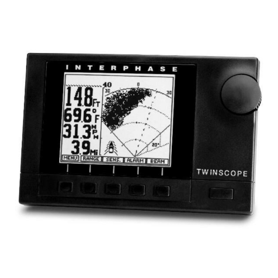
Advertisement
Advertisement
Table of Contents

Related Manuals for Interphase Twinscope


Summary of Contents for Interphase Twinscope
- Page 1 INTERPHASE INTERPHASE TWINSCOPE ™ PERATION ANUAL...
- Page 2 We feel proud of the Twinscope Forward Scanning Sonar and your satisfaction is very important to us. To this end, we welcome any comments or suggestions that you might have in regard to this equipment.
-
Page 3: Table Of Contents
NMEA 0183 Interface Interpreting the Twinscope’s Forward Vertical (Probe) Display Distance Forward Noise and Sensitivity Adjustments Transducer Sidelobe Effect Interpreting the Twinscope’s Forward Horizontal (Sea Scout) Display Noise and Sensitivity Adjustments Reference Information FAQ’s (Frequently Asked Questions) Maintenance Reset Unit & Calibration... -
Page 4: General Information
Twinscope provides instant full screen updates when switching between modes (no data loss). If you have your Twinscope interfaced with a Loran-C or GPS unit, you can take advantage of the included track plot displays. The Loran-C, DECCA, and GPS track plot displays... -
Page 5: Important Notice
The enclosed warranty registration card must be completed and returned to Interphase within 15 days of purchase so that your unit may be protected under the warranty. Failure to return the warranty card may cause unnecessary delays in processing your unit for warranty repair. -
Page 6: Principle Of Operation
For example, using a 16 element phased array transducer, the Twinscope is capable of steering the acoustic beam in any of 90 different directions in either the horizontal or vertical direction. Conventional fixed- beam technology would require the use of 180 different elements to duplicate this capability. - Page 7 It is also important to realize that while the Twinscope shows the bottom in both the forward and the conventional downlooking mode, the presentations are really quite different. The forward scan shows a view as the beam “sweeps”...
-
Page 8: Display Unit Installation
Optional in-dash bracket available. Interphase part # 17-0054-008 Installation Display Unit The compact size of the Twinscope display unit allows for easy installation in almost any vessel. To get maximum performance and life from your unit, the following guidelines should be considered when... -
Page 9: Transducer Connections
It is important that the two leads from the transducer or transducers be connected to the correct connector on the rear of the Twinscope . The label on the rear of the Twinscope shows which transducer cable should be connected to each of the two 9-pin connectors. If these cables are reversed, the Twinscope will not scan correctly. - Page 10 Note: The transom mount Probe (Vertical) and Sea Scout (Horizontal) transducers are almost identical in appearance. If the labels are not readable, you can tell the difference by looking at the mounting brackets. The Sea Scout has a 1/4” hole drilled as shown in the sketches below.
- Page 11 (P/N # 04-0014-008) DANGER: Removal of any connector, disassembly of transducer, shortening of any cable or use of any cable other than that supplied by Interphase will void your warranty. NO EXCEPTIONS. Cable Connectors (view from front of female...
-
Page 12: Transducer Installation
Forward Direction top view Transducer Installation The Twinscope comes standard with either a single or twin thru-hull or with two transom mount forward scanning transducers. An optional speed/temperature transducer is also available which will allow the Twinscope to display current boat speed, surface water temperature and elapsed distance. -
Page 13: Transom Transducer Installation
If you need a longer length cable than comes with the transducer (30’), then purchase the optional 30’ extension cable, Interphase Part # 04-0014-008. In addition to the above, the following considerations should be observed: Choose a location where there is the least amount of acoustic noise, air bubbles or turbulence caused by the boat’s movement. - Page 14 Tramsom Mount Locations Cable Transducer 18 - 24" Cables Twin Outboards Boat’s Hull Transom Mounting Location The main source of vessel acoustic noise is the propeller. It is very important to position the transducers to minimize noise pickup and provide as clear a view as possible of the water ahead of the boat.
- Page 15 After mounting the transducer and actually using the Twinscope on the water, you may need to readjust the transducers' mounting for optimum performance. Mount Transducers So They Will Scan Properly...
-
Page 16: Selecting The Best Location
The Twinscope must have a clear view of the water ahead as it can not magically see through obstructions such as the vessel’s hull. - Page 17 Because the Twinscope scans a 12 degree beam from the surface ahead to directly below the boat, it is important to make sure that the transducer is installed so that it will scan in a vertical direction and not off to either side.
- Page 18 MOLDED FAIRING BLOCK If your installation requires a fairing block, you may either have one made locally, or purchase a molded plactic unit from Interphase or your Interphase distributor. For this transducer, the molded Fairing Block Part Number is: 42-2005-000...
- Page 19 Both the transom and thru-hull S/T transducers are separately installed. The transom mount S/T transducer can be used with the thru-hull depth only transducer if desired. To order, call your local Interphase dealer, or Interphase directly at (831) 477-4944. Bronze Nut Wood or...
-
Page 20: Basic Operation
Control Center simply by turning the control knob. Basic Operation The Twinscope has been designed to be as easy to learn and operate as possible. The raised push-button keys provide a tactile feel to each operation and the Twinscope responds with an audible beep each time a key is pressed. - Page 21 Pre-Programmed Screen Displays Rather than ask you to “build” different screen displays Interphase Twinscope while operating the unit, the Twinscope has seven of the most valuable LCD screen displays pre-programmed into its operating system memory. Thanks to the Multi-Tasking operating system, each of these pre-programmed displays...
- Page 22 Pressing this key again turns the backlight on and off, each time accompanied by a beep. Typical Sub-Menu To turn the Twinscope off, press this key and hold it down for several seconds until the unit goes off. Demo/Simulator Mode...
- Page 23 Although 50% of the acoustic radiation is concentrated within this cone, 50% is also outside the cone which permits the Twinscope to detect targets typically up to twice the cone angle, (i.e. 24 degrees). This means, for example, that at 1,000 feet the Twinscope will typically be able to see targets across a 420 foot width (210 feet each side of center).
-
Page 24: Getting Started
Thru-Hull Transducer(s) Getting Started Check to see that all the components shown at left were included with your Twinscope. If a part is missing, contact your dealer or the Interphase Customer Service Department (831) 477-4944 immediately. WARNING: DO NOT operate the Twinscope with parts missing or with parts other than those obtained through Interphase;... -
Page 25: Vertical And Horizontal Scanning Modes
Interphase Probe sonar. When the horizontal (Sea Scout) scanning mode is selected, the Twinscope will act just like our popular Sea Scout sonar. All of the Twinscope's advanced features including; full screen downlooking view,... - Page 26 When the Twinscope is in the horizontal scanning (Sea Scout) mode, the upper section with the horizontal arrow will be displayed in reverse video (white arrow on black background).
- Page 27 VERTICAL SCAN (PROBE) CONTROL CENTER FLOW CHART CHART/PLOT View DATA View (Large Digits) PLOT View (Track Plot) FWD View (Forward Scan) CHART View (Conventional) CHART/SCAN View SET-UP View (Languages, etc.)
-
Page 28: Set-Up View
The pictures shown in the DEMO mode are representations of what you might see on your Twinscope. In actual use, the picture you will get can vary significantly depending on depth, bottom and water conditions, the speed of your boat and many other factors (see Interpreting The Twinscope’s... -
Page 29: Language Selection
Naut. Mi (Mi) (NMi) Select Menu Language The Twinscope allows the selection of 9 operating languages; English, French, Italian, Spanish, German, Danish, Finnish, Swedish and Greek may be chosen. To select the operating language, press the button labeled LANG. A display window as shown at right will pop up on the screen showing the available languages and the one currently selected. -
Page 30: Forward View (Full Scan)
Press the button labeled "RANGE" to bring up the Range Adjustment soft key menu as shown at left. Press the button labeled "AUTO" if you would like the Twinscope’s internal microprocessor to automatically select and adjust the range as bottom conditions change. To manually adjust the range, press either the range button labeled "... -
Page 31: Alarm Adjustment
If the depth becomes less or greater than the alarm settings, the audio alarm will sound as a warning. If the Deep alarm is activated, the Twinscope will make a slow beeping noise. A Zone Alarm can be created by using both the Shallow and Deep Alarms. - Page 32 The RESET button can be used to quickly select three popular scanning sectors. If the RESET button is pressed once, the Twinscope will return to the full 90 degree sector scan (from straight ahead to below the boat), pressing RESET again will put the Twinscope into one of three far forward sector scans (each sector is approximately 12 degres wide).
-
Page 33: Plot (Track Plot) View
These functions will not work unless you are able to successfully interface a navigational instrument such as a Loran C, Decca or GPS receiver to the Twinscope. (see page 66) From the Command Center select the "Plot View" and press the "GO"... - Page 34 Note: The Twinscope has both a full screen and a split screen track plotter. Both of these Views are updated automatically, regardless of what display screen is in use.
-
Page 35: Chart View
The Twinscope’s phased array transducer can be electronically steered to look directly below the boat. In this mode the Twinscope LCD display will show a picture exactly like conventional fixed beam down- looking fish finders. When in this mode, the Twinscope... - Page 36 (white on black). Press the softkey again to clear the FISH Alarm choose to manually adjust the sensitivity, the Twinscope turns off the AUTO sensitivity mode and it will remain off until the AUTO soft key is again selected. Note:...
-
Page 37: Other Features
Zoom & Bottom Track & Bottom Lock (Split Screen displays) When using the Chart display , the Twinscope can also display a split screen high resolution zoom of any 25% of the depth range, or can show a split screen Bottom Track or Bottom Lock display. - Page 38 Pressing the soft key labeled "FISH" turns the fish symbol on or off. When turned on, the "FISH" soft key will be shown in reverse video and the Twinscope’s microprocessor will scan the output of the receiver and looks for specific patterns which it has been programmed to recognize as fish.
-
Page 39: Data View
"DATA" to see a split screen display with large digits on the left and a forward scanning view on the right. The large digits show the digital depth and, if your Twinscope is equipped with the optional speed/temperature transducer, the boat speed, surface water temperature, and distance traveled log. - Page 40 If the depth becomes less or greater than the alarm settings, the audio alarm will sound as a warning. If the Deep alarm is activated, the Twinscope will make a slow beeping noise. A Zone Alarm can be created by using both the Shallow and Deep Alarms.
- Page 41 The “RESET” button can be used to quickly select three popular scanning sectors. If the “RESET” button is pressed once, the Twinscope will return to the full 90 degree sector scan (from straight ahead to below the boat), pressing “RESET” again will put the Twinscope into a far forward scan and pressing it a third time will set select another far forward scan.
-
Page 42: Chart/Plot View
Chart/Plot View (split screen) In this view, the Twinscope shows a split screen display with a conventional down looking depth sounder picture on the left and a track plot display on the right. Pressing the "GO" soft key will bring up a sub-menu to allow adjustments to the track plotter display. - Page 43 Reset the Track Plot. Note: The Twinscope has both a full screen and a split screen track plotter. Both of these Views are updated automatically regardless of what display screen is in use.
-
Page 44: Chart/Scan View
Chart/Scan View (split screen) In this split screen view, the Twinscope shows a forward looking view on the right and a conventional down looking chart view on the left. In this view, adjustments can be made to the right side of the display (forward looking view) but not to the left side (down looking display). - Page 45 The “RESET” button can be used to quickly select three popular scanning sectors. If the “RESET” button is pressed once, the Twinscope will return to the full 90 degree sector scan (from straight ahead to below the boat), pressing “RESET” again will put the Twinscope into a far forward scan and pressing it a third time will set select another far forward scan.
- Page 46 HORIZONTAL SCAN (SEA SCOUT) CONTROL CENTER FLOW CHART/PLOT View DATA View (Large Digits) PLOT View (Track Plot) FWD View (Forward Scan) SET-UP View (Languages, etc.) CHART/SCAN View CHART View (Conventional)
-
Page 47: Set-Up View
The pictures shown in the DEMO mode are representations of what you might see on your Twinscope. In actual use the picture you will get can vary significantly depending on depth, bottom and water conditions, the speed of your boat and many other factors (see Interpreting The Twinscope’s... -
Page 48: Alignment Adjustment
Once selected, press any key to save your selection and exit. Transducer Alignment The Twinscope includes a feature that will allow you to compensate for some transducer installation problems where the transducer is not pointing straight forward but instead points off to the right or left of the boat. By pressing the softkey labeled “ALIGN”... -
Page 49: Forward View (Full Scan)
"LAST". Sensitivity Adjustment Press the soft key labeled "SENS" (for sensitivity) to bring up the choices available for adjusting the Twinscope's receiver sensitivity. Press the button labeled "AUTO" so that the word AUTO is shown in reverse video (white... - Page 50 (+1 to +32). When you choose to manually adjust the sensitivity, the Twinscope turns off the AUTO sensitivity mode and it will remain off until the AUTO soft key is again selected. To exit the sensitivity menu and save your adjustments simply press the soft key labeled “LAST”...
- Page 51 The RESET button can be used to quickly select three popular scanning sectors. If the RESET button is pressed once, the Twinscope will return to the full 90 degree horizontal sector scan , pressing RESET again will put the Twinscope into one of two preprogrammed forward sector scans.
-
Page 52: Plot (Track Plot) View
If your separate Loran C, Decca or GPS receiver has the proper NMEA version #0183 output capability, or if you own the Interphase Star Pilot GPS, Pilot GPS or Interphase Pilot Loran, you can easily interface the unit to the Twinscope to show both digital and graphic navigation information. - Page 53 Note: The Twinscope has both a full screen and a split screen track plotter. Both of these Views are updated automatically, regardless of what display screen is in use.
-
Page 54: Chart View
The Twinscope’s phased array transducer can be electronically steered to look directly below the boat. In this mode the Twinscope LCD display will show a picture exactly like conventional fixed beam down- looking fish finders. When in this mode, the... - Page 55 (white on black). Press the softkey again to clear the FISH Alarm to manually adjust the sensitivity, the Twinscope turns off the AUTO sensitivity mode and it will remain off until the AUTO soft key is again selected. Note: when AUTO mode is turned on, the word will be displayed in reverse video (white letters on a black background).
- Page 56 Zoom & Bottom Track & Bottom Lock (Split Screen displays) When using the Chart display (conventional down looking view), the Twinscope can also display a split screen high resolution zoom of any 25% of the depth range, or can show a split screen Bottom Track or Bottom Lock display.
- Page 57 Pressing the soft key labeled "FISH" turns the fish symbol on or off. When turned on, the "FISH" soft key will be shown in reverse video and the Twinscope’s microprocessor will scan the output of the receiver and looks for specific patterns which it has been programmed to recognize as fish.
-
Page 58: Data View
"DATA" to see a split screen display with large digits on the left and a forward scanning view on the right. The large numbers show the digital depth and, if your Twinscope is equipped with the optional speed/temperature transducer, the boat speed, surface water temperature, and distance traveled log. - Page 59 When you choose to manually adjust the sensitivity, the Twinscope turns off the AUTO sensitivity mode and it will remain off until the “AUTO” soft key is again selected. Note: when AUTO mode is turned on the word AUTO will be displayed in reverse video (white letters on a black background).
- Page 60 The RESET button can be used to quickly select three popular scanning sectors. If the RESET button is pressed once, the Twinscope will return to the full 90 degree horizontal sector scan , pressing RESET again will put the Twinscope into one of two preprogrammed forward sector scans as shown at right.
-
Page 61: Chart/Plot View
Chart/Plot View (split screen) In this view, the Twinscope shows a split screen display with a conventional down looking depth sounder picture on the left and a track plot display on the right. Pressing the "GO" soft key will bring up a sub-menu to allow adjustments to the track plotter display. - Page 62 Note: All other past information, including track line dots and marks, will be lost when you Reset the Track Plot. Note: The Twinscope has both a full screen and a split screen track plotter. Both of these Views are updated automatically regardless of what display screen is in use.
-
Page 63: Chart/Scan View
Chart/Scan View (split screen) In this split screen view, the Twinscope shows a forward looking display on the right and a conventional down looking chart display on the left. In this view, adjustments can be made to the right side of the display (forward looking view) but not to the left side. - Page 64 Alarm Adjustment In the forward looking display or view, a forward alarm may be set for targets which are closer than a present distance. To adjust or clear the alarm settings, press the soft key labeled “ALARM” to bring up the forward looking alarm menu choices.
- Page 65 The RESET button can be used to quickly select three popular scanning sectors. If the RESET button is pressed once, the Twinscope will return to the full 90 degree horizontal sector scan , pressing RESET again will put the Twinscope into one of two preprogrammed forward sector scans shown at bottom left.
-
Page 66: Nmea 0183 Interface
RMA, RMB, RMC. Consult your GPS operation manuals or contact the manufacturer for further information on interfacing. The Twinscope needs to be interfaced via the eight- pin jack on the rear panel of the display unit. The pin connections are shown at right. -
Page 67: Interpreting The Twinscope's Forward Vertical (Probe) Display
Twinscope’s LCD. Since the Twinscope knows the direction in which it sent the transmit pulse and the time it took to receive the return echo, it can determine the location of the object or bottom that created the return echo. -
Page 68: Distance Forward
LCD screen in their proper position (also known as false echoes). As the Twinscope sends off its acoustic beam in a specific direction, it assumes that any return echoes are within the main beam. However, if the sidelobe energy (which is not within the main beam) strikes a large object (i.e. - Page 69 , and in the worst case, from the bottom below to the surface ahead. After using the Twinscope in different situations, with different gain settings, you should become proficient in identifying the bottom echoes caused by the transducer’s sidelobes.
-
Page 70: Interpreting The Twinscope's Forward Horizontal (Sea Scout) Display
Interpreting The Twinscope’s Forward Horizontal (Sea Scout) Display In the Horizontal (Sea Scout) mode, the Twinscope scans from left to right across the boats bow. The forward scanning elements in the transducer are positioned so that the plane of the horizontal scan is angled downward approximately 10-20 degrees from the water’s surface... -
Page 71: Noise And Sensitivity Adjustments
The top picture and resulting screen display shows a boat in 12 feet of water. The Twinscope’s forward range is set to 40ft Forward Range, Water Depth of 12 Ft 40 ft. Notice on the scan picture on the right side of the display, the bottom is just starting to show at about 35 to 40 ft in front. - Page 72 Examples of two bottom situations, followed by the resulting view on the Twinscope split- screen Chart/Scan Display. Bottom Getting Deeper to port (left) of boat. Sides of Underwater Trench Bottom Under Boat...
-
Page 73: Reference Information
Reference Information Phased Array Technology Most existing depthsounders and fishfinders in the marine market use a mature “fixed beam” technology which was originally developed during W.W. II to detect the presence and distance of submarines. Products using this technology usually have a transducer mounted on the rear of the vessel, making contact with the water. - Page 74 In the future, Interphase believes that this multiple fixed- beam approach has serious limitations, especially for use in more advanced products where maximum underwater coverage and resolution are important.
- Page 75 For example, using two 8 element phased arrays, the Twinscope is capable of steering the acoustic beam in over 90 different angles in two...
-
Page 76: Faq's (Frequently Asked Questions)
What type of transducer is needed and what does it look like? The transducers for the Twinscope are available in transom or thru-hull configurations. If you are operating an inboard, you must use the thru-hull. Remember that... - Page 77 Can I see a regular depth sounder view of the bottom and scan forward or zoom into the bottom at the same time? All Interphase products provide both full screen views as well as split screens for bottom charting, forward scanning or zoom view (depending on the unit's functions), and even Loran/GPS ready track plotting views.
-
Page 78: Maintenance
Follow the maintenance tips below to ensure that your Twinscope remains problem free. 1) Keep your Twinscope clean and dry. Occasionally wipe unit off with a damp cloth, but be careful not to scratch the lens covering the LCD screen. For stubborn dirt, use a mild soap and a damp cloth. NEVER USE SOLVENTS SUCH AS PAINT THINNER, ACETONE, OR GASOLINE TO CLEAN YOUR Twinscope. -
Page 79: Reset Unit & Calibration
‘rooster tails’. The spray shield rests between the transducer tabs in a ‘U’ fashion with the notch facing aft. Product Support: Monday thru Friday 8:00 AM 5:00 PM PST Phone: (831) 477-9685 Ext. 16 Fax: (831) 462-7444 E-Mail: comments@interphase-tech.com Reset & Calibration LCD Display... -
Page 80: Troubleshooting Guide
Troubleshooting Guide If you are experiencing trouble with your Twinscope, please refer to the following checklist: PROBLEM Unit will not turn on. Unit beeps but no picture appears on the screen. Unit blows fuses. Loses picture at speed. LCD darkens in sunlight after prolonged use. -
Page 81: Interference Problems
Twinscope display as each suspected source is turned back on. This type of interference can usually be eliminated by moving the Twinscope away from the source and checking to ensure that the interfering source is properly grounded. -
Page 82: Specifications
Specifications Depth only Transom Transducers Thru-Hull Transducer Part # T1-0200-025 Part # T1-I200-032 & T1-0200-028 Display Type: Depth Ranges: Forward Ranges: Transmit Frequency: Zoom Ranges: Pulselength and Sounding Rates: Transmitter Power: Surface Water Temperature: Power Requirements: Dimensions: Standard Equipment: Specifications subject to change without notice. Two Depth-Only Depth only Single Thru-Hull Transducers... - Page 83 Notes...
-
Page 85: How To Obtain Service
Interference Problems. This information solves the most common problems. If problems persist, please call Interphase Technical Service at (831) 477-4944, ext 16 or send your unit in with the information below filled out. If you do need to return your set, send it to the following address: Service Department Interphase Technologies, Inc. -
Page 87: Warranty
Repair or replacement during the warranty period will not extend the basic warranty period. From the second through the fifth year, Interphase will, at it’s option, repair or replace defective units for a fixed fee. This fee will be set at the beginning of each year.
Need help?
Do you have a question about the Twinscope and is the answer not in the manual?
Questions and answers