Table of Contents
Advertisement
Advertisement
Table of Contents

Related Manuals for Interphase iScan V90


Summary of Contents for Interphase iScan V90
- Page 2 We feel proud of the iScan V90 and your satisfaction is very important to us. To this end, we welcome any comments or suggestions that you might have in regard to this equipment.
-
Page 3: Table Of Contents
Table Of Contents Important Notice Principle of Operation Display Unit Installation Selecting the Transducer Configuration for your Boat____________________________________ 9 Transducer Installation Getting Started Display Colors/Brightness Set-Up Languages/Units More (Max Vert Gain, Remote/ Master) STC Adjustment__________________________________________________________ 20 Transducer Adjustments Demo System Reset_____________________________________________________________ 21 Displays Vertical Down... -
Page 4: Important Notice
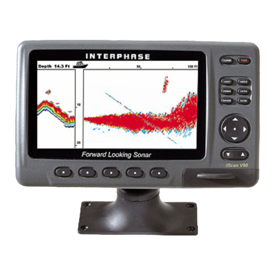
General Information hank you for your selection of the Interphase iScan V90 Forward Scanning Sonar. The iScan V90’s ruggedly built, compact design makes it ideal for installation on nearly any boat. -
Page 5: Principle Of Operation
For example, using an 8 element phased array transducer, the iScan V90 is capable of steering the acoustic beam in any of 60 different directions. Since the acoustic beam in the phased array is steered electronically, requiring no moving parts, it can be quickly and reliably scanned and re-scanned over a large area. -
Page 6: Display Unit Installation
Display Installation Display Unit The compact size of the iScan V90 display unit allows for easy installation in almost any vessel. To get maximum performance and life from your unit, the following guidelines should be considered when selecting a mounting location: 1) Select a location where the unit is protected from excessive temperatures. - Page 7 In - Dash Mounting The iScan V90 comes with mounting hardware to mount the display in-dash. Four mounting screws and a cutout diagram are included. For in-dash mounting, the mounting base portion of the Quick Disconnect Mount is removed. To remove the mounting base loosen the thumb screw until it seperates from the upper portion of the Quick Disconnect Mount.
- Page 8 Wiring and Cable Connectors 9 Pin Transducer Connectors: (view from front of female plug) White 1st element Brown 2nd element Orange 3rd element Yellow 4th element Green 5th element Blue 6th element Violet 7th element Gray 8th element Shield Ground/Return 3 Pin Video Input Ground Return +12 VDC...
-
Page 9: Selecting The Transducer Configuration For Your Boat
Selecting the Transducer Configuration for your Boat Keep in mind the primary rule for transducer operation. This is: the transducer can function as long as it has an unobstructed forward view and has smooth flowing non-aerated water surrounding it. The first line of inquiry should be about the boat. Transom mounted transducers are intended for low speed boats with external props. -
Page 10: Transducer Installation
Prior to installing the transducer review the Selecting the Transducer Configuration guidelines on Page 9. The iScan V90 comes standard with either a thru-hull or transom mounted forward scanning transducer. It is important to position the transducer so that it has as clear a view as possible of the water directly below and ahead of your boat, as indicated at left. - Page 11 30’ Extension Cable 9-pin Interphase Part # Male 04-0014-008 Transom Mount Bracket in Released Position Suggested materials required for installation: ♦ Variable speed electric drill with a chuck capacity of 10mm (3/8”) or larger. ♦ Hole saw or spade bit 19 mm (7/8”) for...
- Page 12 Kick-up Bracket Replacement Parts If during installation parts are somehow lost are damaged, they can be replaced as follows: Part# 17-0088-008 - Spray Shield Kit - Includes: Spray Shield, four Mounting Bolts and Nuts, Rubber Grommet and four Large Mounting Screws. Part# 17-0089-008 - Transom Transducer Hardware Kit - Includes: Complete Bracket Axle Assembly and four Large Mounting Screws.
- Page 13 After mounting the transducer and actually using the iScan V90 on the water, you may need to readjust the transducer’s mounting for optimum performance.
-
Page 14: Selecting The Best Location
The iScan V90 must have a clear view of the water ahead as it can not magically see through obstructions such as the vessel’s hull. - Page 15 Forward require tightening from inside the hull. Because the iScan V90 scans a 12 degree beam from the surface ahead to directly below the boat, it is important to make sure that the transducer is installed so that it will scan in a vertical direction and not off to either side.
- Page 16 2) Use a 1-1/16” hole saw and drill the hole from the outside of the hull. Sand or clean the area around the hole, inside and outside to insure that the sealing compound will adhere properly to the hull. Select a marine grade adhesive sealant, such as 3M 5200, and use according to the instructions.
-
Page 17: Getting Started
ON/OFF - PWR Button. Press the red "PWR" button located at the upper right of the unit to turn the iScan V90 on. The unit will respond with a beep when it turns on. Briefly pressing the PWR button again brings up the menu for adjusting the screen brightness and color. -
Page 18: Display Colors/Brightness
SET-UP Menu, please refer to the SET-UP section on pages 19-20. DEMO Your iScan V90 includes a built-in DEMO simulator program which makes it easy to practice with the unit and to get a feeling for its many features before actually using it in real situations on the water. -
Page 19: Set-Up
MAX G 100 FT MORE The iScan V90 allows you to customize the maximum possible gain for each range. The table below shows a suggested range of Max Gain settings that you can set. Too much gain on the shallow ranges will cause excess noise and false forward targets. - Page 20 To minimize these types of problems, the iScan V90 includes an STC Adjustment. STC stands for Surface Time Constant and you can use it to force the iScan V90 to ignore surface clutter. By default, the STC is set to 5 feet - meaning that the digital depth and alarms will ignore anything closer than 5’...
-
Page 21: Transducer Adjustments
V90’s memory will retain the setting. Demo If the DEMO softkey is pressed the iScan V90 will go into a demonstration mode where simulated data is sent to the display. This mode can be a useful tool to help understand Level Bottom Correctly Shown the operation of the unit. -
Page 22: Displays
Displays The iScan V90 has three basic display modes which can be accessed directly by pressing one of the four buttons with the display’s name. The following paragraphs give a brief description of each of these display modes. More detailed... -
Page 23: Down
ALARM SET-UP Down Display (Conventional down looking) By pressing the DOWN button - once, the iScan V90’s display will split and a conventional downlooking display will appear at the left side of the screen as shown on the right. The downlooking split screen mode will work in either the vertical or horizontal display modes. -
Page 24: Data
NMEA source of this data - such as an active or “smart” NMEA speed/temp transducer and/or a GPS (for example, the Interphase Chart Master Series) or other acceptable source of NMEA data. Please see NMEA INPUTS on page 32 for more details. -
Page 25: Operating Adjustments
Gain Adjustment (Sentivity) Press the button labeled GAIN to bring up the choices available for adjusting the iScan V90 s receiver GAIN. Press the button below AUTO so that the word AUTO is shown with a red border if you would like the Color Twinscope to automatically adjust its receiver gain for changing conditions. -
Page 26: Screen Cursor
(On forward ranges below 200 feet, it’s recommended to keep the gain below the number 10.) Screen Cursor The iScan V90 has a useful screen cursor feature that can show the approximate depth and range from the vessel to any target on a forward scanning display. -
Page 27: Scanning Speed
Use NAV Beam Adjustment Button UP/Down The iScan V90 can scan a 90 degree arc (segment) in a vertical direction. In some cases you may want to reduce adjust the size of the sector and then steer it in a particular beam direction. -
Page 28: Video Input
See diagram at bottom of previous page. Video Inputs The iScan V90 has a 3-pin video input connector on the rear panel. You can connect video cameras, VCR, DVD and other sources of NTSC OR PAL signals to this connector and view them in a full-screen format on the iScan V90’s... -
Page 29: Interpreting The Forward Vertical Display
The Phased Array Transducer steers an acoustic beam over an arc which can be adjusted from approximately 12 to 90 degrees. As the iScan V90 steers the beam to different positions, it transmits a pulse of energy and then waits a defined period of time (depending on the range selected) and listens for any return echoes. -
Page 30: Noise And Sensitivity Adjustments
LCD screen in their proper position (also known as false echoes). As the iScan V90 sends off its acoustic beam in a specific direction, it assumes that any return echoes are within the main beam. -
Page 31: Inputs And Outputs
Blue Inputs and Outputs Video Input A 3-pin connector on the rear of the iScan V90 will accept NTSC or PAL video signals from cameras, VCRs, DVDs and other common video sources. When the Video mode is choosen the iScan V90’s LCD display will show the video input in a full screen format. -
Page 32: Nmea Inputs (Gps, Temp) / Nmea Depth Output
Connect the Mini-USB connector to the port under the rubber protective cover on the front bottom right corner of the iScan V90. Connect the other end of the cable to the USB port of your PC. Note: Detailed upgrade instructions are available on www.interphase-tech.com... -
Page 33: Remote Displays (2Nd Stations)
Master (#1) and the Remote(#2) during operation. The normal iScan V90 will operate as a stand-alone unit or as a Remote unit in a two display installation, but can not operate as a Master unit. -
Page 34: Maintenance
Maintenance Below are some helpful tips for keeping your iScan V90 in top condition: 1) Keep your display clean and dry. Occasionally wipe unit off with a damp cloth, but be careful not to scratch the lens covering the LCD screen. For stubborn dirt, use a mild soap and a damp cloth. NEVER USE SOLVENTS SUCH AS PAINT THINNER, ACETONE, OR GASOLINE TO CLEAN YOUR UNIT. -
Page 35: Interference Problems
V90’s display as each suspected source is turned back on. This type of interference can usually be eliminated by moving the iScan V90 away from the source and checking to ensure that the interfering source is properly grounded. -
Page 36: Specifications
Specifications Display Type: Depth Ranges: Forward Ranges: Transmit Frequency: Transmite Power: Transmit Beam Angle: Pulselength and Sounding Rates: Power Requirements: Operating Temperature: NMEA 0183 Inputs: NMEA 0183 Output Dimensions: Standard Equipment: Transom Transducer Part # T1-I200-025 480 x 234 pixels, Sunlight Color Active Matrix LCD Depth ranges, 0 - 25 to 0 - 600feet Forward ranges, 0 - 50 to 0 - 1,200 feet 200 kHz... -
Page 37: How To Obtain Service
Interference Problems. This information solves the most common problems. If problems persist, please call Interphase Technical Service at (831) 477-4944 Ext: 16 or send your unit in with the information below filled out. If you do need to return your set, send it to the following address: Service Department Interphase Technologies, Inc. - Page 38 Notes...
-
Page 39: Warranty
Repair or replacement during the warranty period will not extend the basic warranty period. From the second through the fifth year, Interphase will, at its option, repair or replace defective units for a fixed fee. This fee will be set at the beginning of each year. - Page 40 2880 Research Park Dr Suite #140 Soquel, CA 95073 PHONE: 831. 477.4944 FAX: 831. 462.7444 comments@interphase-tech.com www.interphase-tech.com...
Need help?
Do you have a question about the iScan V90 and is the answer not in the manual?
Questions and answers