Table of Contents
Advertisement
Quick Links
Advertisement
Table of Contents

Related Manuals for Interphase 180


Summary of Contents for Interphase 180
- Page 2 We feel proud of the iScan 180 and your satisfaction is very important to us. To this end, we welcome any comments or suggestions that you might have in regard to this equipment.
-
Page 3: Table Of Contents
Table Of Contents Important Notice Principle of Operation Display Unit Installation Transducer Installation Auto Switch Module Installation____________________________________________________ 12 In - Dash Mounting______________________________________________________________ 13 Getting Started Display Colors / Brightness / Display Modes Set-Up Languages/Units More (Max Vert Gain, Remote/ Master) STC Adjustment__________________________________________________________ 17 Transducer Adjustments Demo... -
Page 4: Important Notice
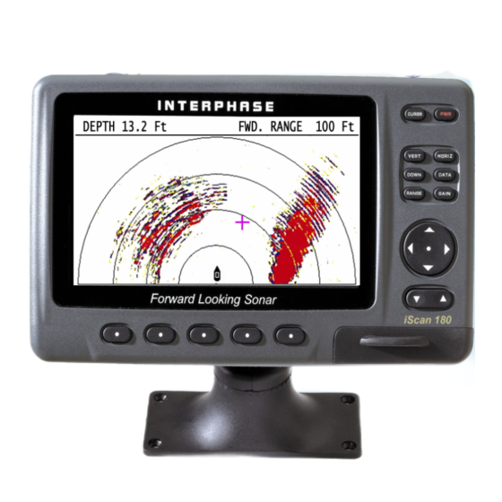
General Information hank you for your selection of the Interphase iScan 180 Forward Scanning Sonar. The iScan 180’s ruggedly built, compact design makes it ideal for installation on nearly any boat. -
Page 5: Principle Of Operation
For example, using an 8 element phased array transducer, the iScan 180 is capable of steering the acoustic beam in any of 60 different directions. Since the acoustic beam in the phased array is steered electronically, requiring no moving parts, it can be quickly and reliably scanned and re-scanned over a large area. -
Page 6: Display Unit Installation
12 VDC Installation Display Unit The compact size of the iScan 180 display unit allows for easy installation in almost any vessel. To get maximum performance and life from your unit, the following guidelines should be considered when selecting a mounting location: 1) Select a location where the unit is protected from excessive temperatures. -
Page 7: Transducer Connections
ORANGE PINK BLUE Transducer Connections MASTER MASTER DISPLAY CONTROL CABLE iSCAN 180 AUTO SWITCH STBD - VERT TRANSDUCER Transducer Connectors - Color Coded: Green = Starboard Vertical Blue = Starboard Horizontal DESCRIPTION GND/COMMON POWER SUPPLY GND (-) POWER +11-16 VDC... -
Page 8: Transducer Installation
The arrays are “potted” in a smooth-surfaced urethane plastic material that is acoustically transparent. Proper performance of your iScan 180 is very dependent on a good transducer installation and normally, thru-hull installations are performed by a professional in a boat haul- out facility. -
Page 9: The Transducers
DO NOT force the cable by pulling on it. This may sever the internal transducer wiring. The Transducers The two iScan 180 transducers are designed to be mounted on opposite sides of the vessel’s keel. Although similar in appearance, the two transducers operate differently and it is important that they be mounted on the proper side of the vessel’s keel. -
Page 10: Using The Fairing Blocks
In this situation, the iScan 180 can only be used at slower vessel speeds which do not result in planing operation. DO NOT install a bronze transducer housing directly into an aluminum or steel hull as electrolytic corrosion will occur. - Page 11 Remove excess sealant from the outside to assure smooth water flow over the transducer. Route the cables back to the iScan 180 Auto Switch Module (black box). If possible, avoid running the cables alongside of antenna cables or other sensitive wiring.
-
Page 12: Auto Switch Module Installation
PORT - HORZ iScan 180 Auto Switch Module Installation The black box that came with your iScan 180 is called the iScan 180 Auto Switch Module (ASM). It houses the switches that control which phased array is being used. Select a location to mount the ASM. Keep in mind that the unit must be protected from from moisture and extreme temperatures. -
Page 13: In - Dash Mounting
In - Dash Mounting The iScan 180 comes with mounting hardware to mount the display in-dash. Four mounting screws and a cutout diagram are included. For in-dash mounting, the mounting base portion of the Quick Disconnect Mount is removed. To remove the mounting base loosen the thumb screw until it seperates from the upper portion of the Quick Disconnect Mount. -
Page 14: Getting Started
ON/OFF - PWR Button. Press the red "PWR" button located at the upper right of the unit to turn the iScan 180 on. The unit will respond with a beep HORIZ when it turns on. Briefly pressing the PWR button again brings DATA up the menu for adjusting the screen brightness and color. -
Page 15: Display Colors / Brightness / Display Modes
SET-UP section on page 16-18. DEMO Your iScan 180 includes a built-in DEMO program which makes it easy to practice with the unit and to get a feeling for its many features before actually using it in real situations on the water. -
Page 16: Set-Up
MAX G 100 FT MORE The iScan 180 allows you to customize the maximum possible gain for each range. The table below shows a suggested range of Max Gain settings that you can set. Too much gain on the shallow ranges will cause excess noise and false forward targets. - Page 17 To minimize these types of problems, the iScan 180 includes an STC Adjustment. STC stands for Surface Time Constant and you can use it to force the iScan 180 to ignore surface clutter. By default, the STC is set to 5 feet - meaning that the digital depth and alarms will ignore anything closer than 5’...
-
Page 18: Transducer Adjustments
L= 3.1 Ft K= +10 Demo If the DEMO softkey is pressed the iScan 180 will go into a demonstration mode where simulated data is sent to the display. This mode can be a useful tool to help understand the operation of the unit. To exit the DEMO mode, press the DEMO softkey again. -
Page 19: Displays
Displays The iScan 180 has four basic display modes which can be accessed directly by pressing one of the four buttons with the display’s name. The following paragraphs give a brief description of each of these display modes. More detailed... -
Page 20: Down / Down Zoom
ALARM SET-UP Down Display (Conventional down looking) By pressing the DOWN button - once, the iScan 180’s display will split and a conventional downlooking display will appear at the left side of the screen as shown on the right. The downlooking split screen mode will work in either the vertical or horizontal display modes. -
Page 21: Data
(see drawing at right). *In order for the iScan 180 to show the speed, temperature and Lat/Lon coordinates, the unit must be connected to an NMEA source of this data - such as an active or “smart”... -
Page 22: Operating Adjustments
180 s receiver GAIN. Press the button below AUTO so that the word AUTO is shown with a red border if you would like the iScan 180 to automatically adjust its receiver gain for changing conditions. -
Page 23: Screen Cursor
(On forward ranges below 200 feet, it’s recommended to keep the gain below the number 10.) Screen Cursor The iScan 180 has a useful screen cursor feature that can show the approximate depth and range from the vessel to any target on a forward scanning display. -
Page 24: Scanning Speed
CLEAR symbol to disable the ALARM and exit. Beam Adjustment The iScan 180 can scan a 90 degree vertical arc (segment) or a 180 degree horizontal arc. In some cases you may want to reduce the size of the sector and then steer it in a particular direction. -
Page 25: Video Input & Output
See diagram at bottom of previous page. Video Input & Output The iScan 180 has a 3-pin video input connector on the rear panel. You can connect video cameras, VCR, DVD and other sources of NTSC OR PAL signals to this connector and view them in a full-screen format on the iScan 180’s... -
Page 26: Interpreting The Vertical Display
The Phased Array Transducer steers an acoustic beam over an arc which can be adjusted from approximately 12 to 90 degrees. As the iScan 180 steers the beam to different positions, it transmits a pulse of energy and then waits a defined period of time (depending on the range selected) and listens for any return echoes. -
Page 27: Distance Forward
LCD screen in their proper position (also known as false echoes). As the iScan 180 sends off its acoustic beam in a specific direction, it assumes that any return echoes are within the main beam. -
Page 28: Interpreting The Horizontal Display
It is important to understand that when the iScan 180 is in the Horizontal display mode, in shallow water - it will typically show the bottom on the forward display. - Page 29 Beam Depth at Various Forward Ranges Forward Range Beam Depth = Approx. 0.18 X Forward Distance In certain conditions - especially in shallow water - you may see a horizontal display that shows a target ahead that remains on the screen at the same distance - even as the boat moves.
-
Page 30: Inputs And Outputs
Blue Inputs and Outputs Video Input A 3-pin connector on the rear of the iScan 180 will accept NTSC or PAL video signals from cameras, VCRs, DVDs and other common video sources. When the Video mode is choosen, the iScan 180’s LCD display will show the video input in a full screen format. -
Page 31: Nmea Inputs (Gps, Temp) / Nmea Depth Output
Quick Disconnect Mount, and the Temperature and Speed source should be connected between the Brown(+) and Green(-) wires. The iScan 180 looks for the following NMEA 0183 V2.0 sentences to get information on positon, speed and temperature. ( Lat/Lon Postion) -
Page 32: Remote Displays (2Nd Stations)
Module which connects to the Master (#1) unit. The Remote (#2) is connected to the Auto Switch Module Via the Remote Display and Remote Control Cables. The iScan 180 Display will operate as a stand-alone unit, a Remote or Master unit in a two display installation. 30’ Remote 4-Pin The iScan 180 Remote Station Kit includes A 9-pin 30’... -
Page 33: Software Upgrades
Connect the Mini-USB connector to the port under the rubber protective cover on the front bottom right corner of the iScan 180. Connect the other end of the cable to the USB port of your PC. Note: Detailed upgrade instructions are available on our website at www.interphase-tech.com... -
Page 34: Maintenance & Trouble Shooting Tips
Maintenance Below are some helpful tips for keeping your iScan 180 in top condition: 1) Keep your display clean and dry. Occasionally wipe unit off with a damp cloth, but be careful not to scratch the lens covering the LCD screen. For stubborn dirt, use a mild soap and a damp cloth. NEVER USE SOLVENTS SUCH AS PAINT THINNER, ACETONE, OR GASOLINE TO CLEAN YOUR UNIT. -
Page 35: Interference Problems
180’s display as each suspected source is turned back on. This type of interference can usually be eliminated by moving the iScan 180 away from the source and checking to ensure that the interfering source is properly grounded. -
Page 36: Specifications
180 Transducer Configuration PORT Horizontal Port Scanning Transducer Part# T1-I200-35 Transducer Fairing Blocks included with iScan 180 Transducer specifications subject to change without notice. 10’ 9-Pin Master Display Cable - Part# 04-0014-010 10’ 4-Pin Master Control Cable - Part# 04-1054-000... -
Page 37: How To Obtain Service
Interference Problems. This information solves the most common problems. If problems persist, please call Interphase Technical Service at (831) 477-4944 or send your unit in with the information below filled out. If you do need to return your set, send it to the following address: Service Department Interphase Technologies, Inc. - Page 38 Notes...
-
Page 39: Warranty
Interphase Technologies, Inc. 5 Year Limited Warranty Any unit that fails during the first year of the warranty period will, at Interphase’ option, be repaired or replaced at no charge to the customer provided it is returned to Interphase, freight prepaid with proof of date of purchase and a description of the malfunction. - Page 40 2880 Research Park Dr Suite #140 Soquel, CA 95073 PHONE: 831. 477.4944 FAX: 831. 462.7444 comments@interphase-tech.com www.interphase-tech.com...
Need help?
Do you have a question about the 180 and is the answer not in the manual?
Questions and answers