Advertisement
Quick Links
Advertisement

Related Manuals for UTC Fire and Security interlogix Concord 4


Summary of Contents for UTC Fire and Security interlogix Concord 4
- Page 1 Concord 4 Installation Manual P/N 466-2182 • REV J • NOV12...
- Page 2 © 2012 UTC Fire & Security Americas Corporation, Inc. Copyright Interlogix is part of UTC Climate Controls & Security, a unit of United Technologies Corporation. All rights reserved. This document may not be copied in whole or in part or otherwise reproduced without prior written consent from UTC Fire &...
- Page 3 Content Important information iii Chapter 1 Introduction 1 Planning the installation 2 SuperBus 2000 bus devices 3 Chapter 2 Installation 5 Installation overview 6 Mounting the panel 10 Intrusion detection devices 15 Smoke detectors 15 Speakers and sirens 18 SuperBus 2000 touchpads 22 SuperBus 2000 modules 22 Phones 28 Power 30...
- Page 4 Troubleshooting Appendix A System planning sheets 117 Customer information 118 Wireless devices 118 Hardware devices 119 Zone and sensor assignments 121 System settings index and record 124 Appendix B Reference tables 129 Sensor group characteristics 130 Sensor text 134 System event triggers 136 Sensor group event triggers 137 Sensor number event triggers 138 System feature event triggers 141...
- Page 5 Important information Intended use Use this product only for the purpose it was designed for; refer to the data sheet and user documentation for details. For the latest product information, contact your local supplier or visit us online at www.utcfireandsecurity.com. Changes or modifications not expressly approved by UTC Fire &...
- Page 7 Chapter 1 Introduction Summary This chapter provides information to help you plan your Concord 4 panel and system installation. Content Planning the installation 2 Standard panel 2 SuperBus 2000 bus devices 3 Concord 4 Installation Manual...
- Page 8 Chapter 1: Introduction Planning the installation This section describes system capabilities to help you get familiar with the system. Appendix A “System planning sheets” on page 117 provides planning sheets that let you record the hardware and programming configuration of the system.
- Page 9 Chapter 1: Introduction Built-in RF receiver Allows use of up to 96 (Concord 4) or 32 (Concord Express v4) 319.5 MHz. crystal and/or SAW learn mode wireless sensors and touchpads. Phone line connection Allows panel to communicate with central monitoring station and/or pagers.
- Page 10 Chapter 1: Introduction SnapCards The following SnapCards expand the system as described: 8Z input Snapcard: Provides eight additional hardwired zone inputs, of which two are dedicated for using two-wire smoke detectors. 4 output SnapCard: Provides four form C relay outputs that can be set up to activate other signaling devices, based on system events, schedules, or direct control.
- Page 11 Chapter 2 Installation Summary This chapter provides information on locating and installing the panel and system components. Content Error! Bookmark not defined. Concord 4 Installation Manual...
- Page 12 Chapter 2: Installation Installation overview Before starting the installation, plan your system layout and programming using the worksheets provided in Appendix A “System planning sheets” on page 117. Note: Class 2, Class 3, and power-limited fire alarm circuits must be installed using FPL, FPLR, FPLP, or substitute cable permitted by the National Electrical Code ANSI/NFPA 70 or Class 2, Class 3, and power-limited fire alarm circuit conductors must be installed as Class 1 or higher circuits.
- Page 13 Chapter 2: Installation Figure 1: Panel and component locations on a wall Total system power and wire length guidelines The panel can supply up to 1 amp (1,000 mA) in full load alarm condition for system devices connected to panel terminals 4 (+12V), 7 and 8 (speaker terminals), 9 (OUT1), 11 (+12V), 24 (2W SMK ZONE 8), and SnapCard terminals.
- Page 14 Chapter 2: Installation Table 4 below describes the maximum wire length allowed between compatible devices and the panel, and the minimum and maximum current draw of each device. Table 4: Wire length requirements Device Max. wire Standby mA Alarm mA draw length to draw panel...
- Page 15 Chapter 2: Installation Device Max. wire Standby mA Alarm mA draw length to draw panel SuperBus 2000 energy saver module 22 ga.: 1,600 20 mA 20 mA 18 ga.: 4,000 SuperBus 2000 automation module 22 ga.: 1,500 30 mA 35 mA 18 ga.: 4,000 SuperBus 2000 wireless cellular gateway 22 ga.: 40 ft.
- Page 16 Chapter 2: Installation Wire type Total system wire 22-gauge, unshielded 4,000 ft. 22-gauge, shielded 3,000 ft. Table 6: Device wire requirements Device Wire requirements AC power transformer 2-conductor, 18-gauge, 25 ft. max. Earth ground Single conductor, 16-gauge solid, 25 ft. max. Telephone (RJ-31X) 4-conductor Detection devices...
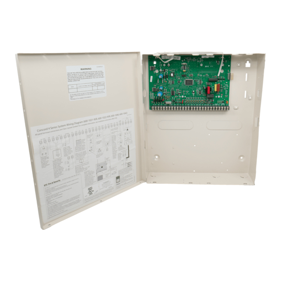
- Page 17 Chapter 2: Installation 5. Partially insert screws into the two top mounting hole locations, then hang the panel on the two screws. 6. Recheck for level, insert the two lower screws, and tighten all four mounting screws. Figure 2: Panel components and mounting holes Antennas Mounting hole Mounting hole...
- Page 18 Chapter 2: Installation Antenna shrouds Install a plastic antenna shroud (included with panel) over each antenna and snap them into the holes on the top of the enclosure (skip this step for hybrid and commercial systems). Concord 4 Installation Manual...
- Page 19 Chapter 2: Installation Optional SnapCards Use the SnapCard header on the right side of the panel (Figure 4 below) to install an optional SnapCard. Install the SnapCard onto the panel SnapCard header and secure it in place with two screws, included with the SnapCard. To connect all necessary input/output wiring, refer to the SnapCard documentation.
- Page 20 Chapter 2: Installation Panel terminals Figure 5 below shows an overview of panel terminals. The following sections provide details on how to connect devices to the panel. Figure 5: Panel terminals GND ZONE1 ZONE2 GND ZONE3 ZONE4 GND ZONE5 ZONE6 GND ZONE7 ZONE8 GRN 16.5 VAC +12V SPKR SPKR...
Need help?
Do you have a question about the interlogix Concord 4 and is the answer not in the manual?
Questions and answers