Advertisement
Quick Links
-
Phillips screwdriver
-
T wrenches size 5-6-8-10
-
Combination ratcheting wrench 17 and/or open-end wrench 17
-
Scissors
-
Electric screwdriver with Phillips head and/or Phillips screwdriver
-
Hand truck and/or platform trolley
NB
-
The hardware is contained in an appropriate blister with the relative
-
The guards are extremely delicate (once unpacked they get dirty very
easily)
-
The weight of the machine is concentrated around the seat area
-
In order to anchor the machine to the ground, position the plates before closing the guards
drafted by Fabrizio Frattini
approved by Andrea Borghesi
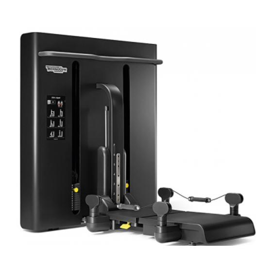
INSTALLATION MANUAL FOR
KINESIS STATIONS STEP MH67E
EQUIPMENT REQUIRED FOR INSTALLATION
PERSONS REQUIRED FOR INSTALLATION
1
02/02/2012
revision 1/1
Advertisement

Related Manuals for Technogym MH67E


Summary of Contents for Technogym MH67E
- Page 1 02/02/2012 INSTALLATION MANUAL FOR KINESIS STATIONS STEP MH67E EQUIPMENT REQUIRED FOR INSTALLATION Phillips screwdriver T wrenches size 5-6-8-10 Combination ratcheting wrench 17 and/or open-end wrench 17 Scissors Electric screwdriver with Phillips head and/or Phillips screwdriver Hand truck and/or platform trolley...
- Page 2 02/02/2012 General information HARDWARE Blister letter-code Description Quantity A - 0Z050 M10x85 screw B - 0Z126 M10x35 screw C - 0ZV00071 M10x30 screw D - 0Z208 M8x16 screw E - 0Z165 M5x10 screw F - 0Z415 M10 self-locking G - 0Z 306 10.5x20x2 washer H - 0N001389 plate...
-
Page 3: Machine Unpacking
02/02/2012 MACHINE UNPACKING DO NOT USE A CUTTER MACHINE UNPACKING SEQUENCE phase 1 Operator A Operator B Remove the cardboard packaging box drafted by Fabrizio Frattini revision 1/1 approved by Andrea Borghesi... - Page 4 02/02/2012 phase 2 Operator A Operator B Remove part of the RH-LH wooden frame (black Extract the machine components and place them near the broken line) unpacking zone Remove 2+2 screws of the RH-LH wooden crossbeams (see detail) drafted by Fabrizio Frattini revision 1/1 approved by Andrea Borghesi...
- Page 5 02/02/2012 phase 3 Operator A Operator B Cut the lower cable tie securing the wooden frame (do not cut the 4 upper cable ties), position the hand truck, separate the wooden frame from the pallet and transport the machine to the area near the unpacking zone drafted by Fabrizio Frattini revision 1/1 approved by Andrea Borghesi...
- Page 6 02/02/2012 phase 4 Operator A/B Remove wooden frame "A" and remove the polyethylene packet drafted by Fabrizio Frattini revision 1/1 approved by Andrea Borghesi...
- Page 7 02/02/2012 phase 5 Operator A/B Transport the machine to the assembly zone using the hand truck or platform trolley depending on the type of zone + the components drafted by Fabrizio Frattini revision 1/1 approved by Andrea Borghesi...
- Page 8 02/02/2012 MACHINE ASSEMBLY SEQUENCE phase 1 Operator A/B Turn the step unit by 90° (F1), turn the platform u nit by 90° and join it to the step unit (F2), tight en with 2 screws + 2 washers (F3) (REMEMBER TO PLACE A CARDBOARD PROTECTION SHEET BETWEEN THE FLOOR AND SEAT ASSEMBLY) Turn the platform assembly by 90°...
- Page 9 02/02/2012 phase 2 Operator A Operator B Feed the cables through on the RH side of the Feed the cables through on the LH side of the machine Loosen the 4 screws (leaving them inserted) of the pivoting unit box, remove the cover Remove the front pivoting unit by levering on the side hook Repeat the same sequence of operations as operator A...
- Page 10 02/02/2012 phase 3 Operator A Operator B feed the cables through (starting from the cable coming out of the RH pulley) Repeat the same sequence of operations as operator A drafted by Fabrizio Frattini revision 1/1 approved by Andrea Borghesi...
- Page 11 02/02/2012 phase 4 Operator A Operator B Repeat the same sequence of operations as operator A drafted by Fabrizio Frattini revision 1/1 approved by Andrea Borghesi...
- Page 12 02/02/2012 phase 5 Operator A Operator B Remove the pivoting unit by levering on the side hook Remove the lower guard of the pivoting unit by loosening the internal screw Repeat the same sequence of operations as operator A Feed the cables through (starting from the cable coming out of the RH central shaft) drafted by Fabrizio Frattini revision 1/1...
- Page 13 02/02/2012 phase 6 Operator A Operator B Repeat the same sequence of operations as operator A tighten the lower guard before inserting the pivoting unit drafted by Fabrizio Frattini revision 1/1 approved by Andrea Borghesi...
- Page 14 02/02/2012 phase 7 Operator A Operator B Insert the ends of the RH cable in the appropriate housings of the RH handle (the RH and LH handles are interchangeable) to unscrew the barrel, insert the L- shaped key in the appropriate hole, thereby creating an opposite movement to that of the T-wrench Effect the same sequence of operations as operator A...
- Page 15 02/02/2012 phase 8 Operator A Operator B Extract the platform, position it in the frame Insert 10 well nuts in the frame assembly assembly and tighten with 2 screws + 2 washers Remove the packaging from the central frame unit (L), insert the latter in the frame assembly in the appropriate housings and tighten with 2 screws (M) drafted by Fabrizio Frattini...
- Page 16 02/02/2012 phase 9 Operator A Operator B Remove the guard packaging, extract the RH Extract the LH guard and insert it in the frame assembly guard and insert it in the frame assembly starting starting from the top and moving towards the bottom; tighten from the top and moving towards the bottom;...
- Page 17 02/02/2012 phase 10 Operator A Operator B Testing of the machine Delivery of the documentation and explanation of machine Cleaning of the assembly zone operation to the customer WARNING If the machine needs to be moved after it has been installed, be careful with the guard of the front foot (shown in the picture).
- Page 18 02/02/2012 ANCHORING THE MACHINE TO THE FLOOR In order to anchor the machine to the floor, proceed in the same manner on both sides of the machine: secure the brackets (M) with the screws (C), nuts and washers (the hardware is pre-mounted on the frame). Mark the points to be drilled on the floor.
Need help?
Do you have a question about the MH67E and is the answer not in the manual?
Questions and answers