Intermec ScanImage 1470 User Manual
Imager
Hide thumbs
Also See for ScanImage 1470:
- Supplementary manual (1 page) ,
- User manual (142 pages) ,
- Quick start manual (16 pages)
Table of Contents
Advertisement
Quick Links
Advertisement
Table of Contents
Troubleshooting

Related Manuals for Intermec ScanImage 1470


Summary of Contents for Intermec ScanImage 1470
- Page 1 User’s Manual P/N 067054-003 1470/1471 Imager...
- Page 2 The information contained herein is proprietary and is provided solely for the purpose of allowing customers to operate and/or service Intermec manufactured equipment and is not to be released, reproduced, or used for any other purpose without written permission of Intermec.
- Page 3 Manual Change Record This page records the changes to this manual. The manual was originally released as version 001. Version Date 6/98 6/01 Description of Change This manual was changed to add information for the 1470 imager. This manual was changed to add information for the Rev. B release of the 1470/1471 imager.
- Page 4 DCS 300 User’s Manual blank...
-
Page 5: Table Of Contents
Before You Begin xv Warranty Information xv Safety Summary xv Warnings, Cautions, and Notes xvi About This Manual xvii Other Intermec Manuals xviii Introduction and Installation About the 1470/1471 Imager 1-3 Unpacking the Imager 1-3 Accessories 1-4 1470 Imager Identification 1-5... - Page 6 1470/1471 Imager User’s Manual CODE39 All Symbologies 3-6 Revision Selections 3-6 Terminal Interface 3-7 Supported Terminals Chart 3-8 Keyboard Country 3-9 Keyboard Style 3-10 Keyboard Modifiers 3-12 Keyboard Function Relationships 3-13 Communication Settings 3-15 Parity 3-16 Baud Rate 3-17 Word Length Data Bits 3-18 Word Length Stop Bits 3-19 Hardware Flow Control 3-19 Software Flow Control 3-20...
- Page 7 Setting the Beeper 3-35 Beeper Default 3-36 Beeper Volume 3-37 Power Up Beeper 3-38 Output Sequence Beeper 3-39 Beep On Decode 3-40 Intercharacter, Interfunction, and Intermessage Delays 3-41 Intercharacter Delay 3-41 Interfunction Delay 3-42 Intermessage Delay 3-43 Prefix/Suffix Overview 3-44 Points to Keep In Mind 3-45 Adding a Prefix or Suffix 3-45 Clearing One or All Prefixes or Suffixes 3-47...
- Page 8 1470/1471 Imager User’s Manual CODE39 Multiple Bar Codes 3-73 No Read 3-74 Print Weight 3-75 Function Code Transmit 3-76 Centering 3-76 Symbologies Introduction 4-3 Linear Symbologies 4-3 Codabar 4-4 Code 39 4-9 Code 11 4-16 Interleaved 2 of 5 4-18 IATA 2 of 5 4-22 MSI 4-24 Code 93 4-26...
- Page 9 Code 128 4-28 Code 128 On/Off 4-29 Message Length 4-29 ISBT 4-31 EAN/JAN 8 4-32 EAN/JAN 8 On/Off 4-33 Check Digit 4-34 EAN/JAN 8 Addenda 4-35 EAN/JAN 8 Addenda Required 4-36 EAN/JAN 8 Addenda Separator 4-37 EAN/JAN 13 4-38 EAN/JAN 13 On/Off 4-39 Check Digit 4-40 EAN/JAN 13 Addenda 4-41 EAN/JAN 13 Addenda Required 4-42...
- Page 10 1470/1471 Imager User’s Manual CODE39 PDF 417 4-69 Micro PDF 417 4-72 Code 49 4-74 Composite Codes 4-76 Postal Symbologies 4-79 U.S. Postal Service POSTNET Code 4-79 Planet Code 4-80 British Post Office 4 State Code 4-80 Canadian 4 State Code 4-81 Dutch Postal Code 4-82 Australian 4 State Code 4-83 Japanese Postal Service 4-84...
- Page 11 Using QuickView QuickView Demonstration Software Instructions 5-3 Installing QuickView 5-3 Temporary Keyboard Wedge QuickView Configuration 5-4 Using the QuickView Software 5-4 Scan Data Window 5-5 Demo Screens 5-7 Electronic Parts Manufacturing Demonstration 5-7 Shipping Demonstration 5-8 Patient Registration Demonstration 5-8 Bills of Lading Demonstration 5-10 Signature Capture Demonstration 5-11 Snapshot 5-12...
- Page 12 1470/1471 Imager User’s Manual CODE39 Exit Selections 6-15 Default Charts General Defaults 7-3 Communication (RS-232) Selections 7-3 Imager Selections 7-4 Prefix/Suffix Selections 7-4 Data Formatter Selections 7-5 Output Sequence Selections 7-5 Linear Symbologies 7-5 Stacked Symbologies 7-7 Postal Symbology Selections 7-8 2D Matrix Selections 7-8 Interface Keys IBM AT/XT, PS/2, XTs, WYSE PC/AT, DDC, Memorex Telex, Harris 8-3...
- Page 13 Specifications and Pinouts 1470 Specifications A-3 1471 Specifications A-4 Depth of Field Charts A-6 Depth of Field for High Density Imager (5.1 cm [2 in.] Nominal Focus) A-6 Depth of Field for Standard Range Imager (17.8 cm [7 in.] Nominal Focus) A-6 Cable Pinouts for RS-232 Output, External Power A-7 1470 Dimensions A-8 1471 Dimensions A-9...
- Page 14 blank...
-
Page 15: Before You Begin
To receive a copy of the standard warranty provision for this product, contact your local Intermec support services organization. In the U.S. call 1-800-755-5505, and in Canada call 1-800-668-7043. If you live outside of the U.S. or Canada, you can find your local Intermec support services organization on the Intermec Web site at www.intermec.com. -
Page 16: Warnings, Cautions, And Notes
1470/1471 Imager User’s Manual Warnings, Cautions, and Notes The warnings, cautions, and notes in this manual use the following format. Warning A warning alerts you of an operating procedure, practice, condition, or statement that must be strictly observed to avoid death or serious injury to the persons working on the equipment. -
Page 17: About This Manual
About This Manual All the information you need to install, configure, operate, maintain, and troubleshoot the 1470 and 1471 imagers is in this manual. Information in this manual should be used by the person who will be installing and configuring the 147X imagers. This manual assumes that you are familiar with your network and data communications. -
Page 18: Other Intermec Manuals
You may need additional information when working with the 147X in a data collection system. Please visit our Web site at www.intermec.com to download many of our current manuals in PDF format. To order printed versions of the Intermec manuals, contact your local Intermec representative or distributor. -
Page 19: Introduction And Installation
Introduction and Installation... - Page 20 blank...
-
Page 21: About The 1470/1471 Imager
This chapter explains how to unpack and install the 1470 and 1471 imagers. About the 1470/1471 Imager The 1470/1471 imager is an economical, durable solution for a wide variety of data collection applications. The imager features the following: • A tough, ergonomic thermoplastic housing for comfort and durability •... -
Page 22: Accessories
1470/1471 Imager User’s Manual 4. Check for damage during shipment. Report damage immediately to the carrier who delivered the carton. Accessories You can order the following accessories for the 147X imager: • A universal power supply and power cable • An interface cable •... -
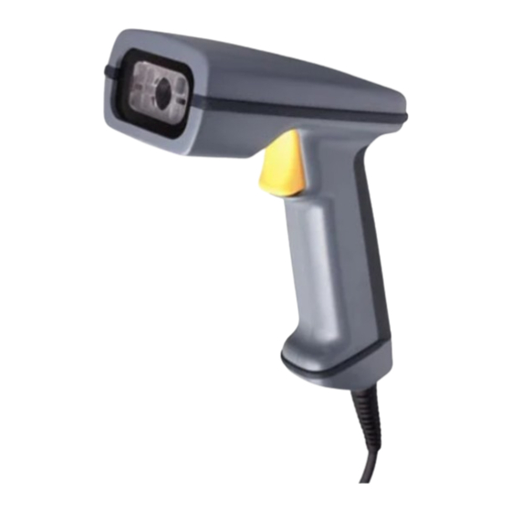
Page 23: 1470 Imager Identification
Introduction and Installation 1470 Imager Identification 147XU001.eps... -
Page 24: 1471 Imager Identification
1470/1471 Imager User’s Manual 1471 Imager Identification Connecting the Imager in Keyboard Wedge Mode You can connect an imager between the keyboard and PC as a “keyboard wedge,” plugged into the serial port, or connected to a portable data terminal in non-decoded output mode. -
Page 25: Connecting The Imager To A Serial Port
Introduction and Installation 3. Connect the appropriate interface cable to the imager and to the terminal/computer. 4. Connect the power supply (4 to 9V). The imager beeps twice. 5. Turn the terminal/computer power back on. 6. Verify the imager operation by scanning a bar code. The imager beeps once. The imager is now connected and ready to communicate with your terminal/PC. - Page 26 1470/1471 Imager User’s Manual Connecting the Imager to a Serial Port 5. Turn the terminal/computer power back on. 6. Verify the imager operation by scanning a bar code from Appendix B, “Sample and Programming Bar Codes.” The imager beeps once. The imager is now connected and ready to communicate with your terminal/PC.
-
Page 27: Reading Techniques
Introduction and Installation Reading Techniques The hand-held imager has a view finder that projects a bright red aiming beam that corresponds to the imager’s horizontal field of view. The aiming beam should be centered over the bar code, but it can be positioned in any direction for a good read. Linear Bar Code 2D Matrix Bar code The aiming beam is smaller when the imager is closer to the code and larger when it is... - Page 28 blank...
-
Page 29: Installing Visual Menu
Installing Visual Menu... - Page 30 blank...
-
Page 31: Visual Menu Introduction
This chapter explains how to install and use Visual Menu. Visual Menu Introduction You can use Visual Menu to configure the imager by connecting it to the COM port of a PC. Visual Menu allows you to download upgrades to an imager’s firmware, change programmed parameters, and create and print programming bar codes. -
Page 32: Temporary Keyboard Wedge Visual Menu Configuration
2. Place the CD-ROM that shipped with the 147X imager into your CD-ROM drive. Your Web browser opens. 3. Choose a language for the screens to appear in. 4. Click the ScanImage 1470/1471. 5. Click Software. 6. Click Install Visual Menu. -
Page 33: Programming The 147X
Programming the 147X... - Page 34 blank...
-
Page 35: Introduction
Use this chapter to program the 147X imager. Introduction This chapter contains the following sections: • Reset Factory Settings • Status Check • All Symbologies • Revision Selections • Terminal Interface • Supported Terminals Chart • Keyboard Country • Keyboard Style •... -
Page 36: Reset Factory Settings
1470/1471 Imager User’s Manual Reset Factory Settings All operating parameters are stored in nonvolatile memory resident in the imager, where they are permanently retained in the event of a power interruption. When you receive your imager, certain operating parameters have already been set. These are the factory defaults. -
Page 37: Status Check
Programming the 147X Status Check You can see the software revision in the General tab of Visual Menu. Read the Show Software Revision bar code to transmit the software revision level to the host terminal. The software revision will be printed out as “REV_SW: $ProjectRevision: 1.xx $;REV_WA: 31204734-xxx.”... -
Page 38: All Symbologies
1470/1471 Imager User’s Manual All Symbologies If you want to decode all the symbologies allowable for your imager, scan the All Symbologies On code. In Visual Menu, you need to turn on each symbology individually. All Symbologies On Revision Selections Power PC Revision and Boot Code Revision would not normally be needed unless you have a problem with the imager. -
Page 39: Terminal Interface
Or scan one of the following bar codes. Power PC Revision Terminal Interface 1470 and 1471 imagers are factory programmed for an RS-232 interface. If this is your interface and you do not need to modify the settings, skip to “Power Saving Mode” later in this chapter to begin programming the imager. -
Page 40: Supported Terminals Chart
1470/1471 Imager User’s Manual Supported Terminals Chart Terminal DELL Fujitsu HHLC (Code 128 Emulation) Midwest Mitak Olivetti Olivetti Reliasys RS-232 TTL Televideo Texas Instruments Toshiba Toshiba Zenith Model(s) PC433 SE (Portable PC) Latitude (Portable PC) 486 SLC (Portable PC) Stylistic (Portable PC) PC XT PS/2 25, 30, 77DX2 AT, PS/2 30-286, 50, 55SX, 60, 70,... -
Page 41: Keyboard Country
Programming the 147X Keyboard Country As a general rule, the following characters are not supported by the imager for countries other than the United States: @ | $ # { } [ ] = / ‘ \ < > ~ Note: If your imager does not support Keyboard Wedge settings, the Keyboard Wedge tab does not appear in Visual Menu. -
Page 42: Keyboard Style
1470/1471 Imager User’s Manual Or scan the Keyboard Country bar code below, then scan the numeric bar code(s) from the “General Programming Chart” in Appendix B, then the Save bar code to program the keyboard for your country. Keyboard Country Country Code Belgium Denmark... - Page 43 • Emulate External Keyboard is used if you do not have an external keyboard (IBM AT or equivalent). To connect to a laptop, you must configure for Emulate External Keyboard mode, then set Automatic Direct Connect Mode On. For help setting Automatic Direct Connect Mode, see “Keyboard Modifiers”...
-
Page 44: Keyboard Modifiers
1470/1471 Imager User’s Manual Keyboard Modifiers This section explains how to modify special keyboard features: Control + ASCII Mode On The imager sends key combinations for ASCII control characters for values 00-1F. For CTRL+ ASCII Values, see “Keyboard Function Relationships” later in this chapter. Turbo Mode The imager sends characters to an IBM AT terminal faster (for use with IBM AT only). -
Page 45: Keyboard Function Relationships
Keyboard Modifiers (continued) Turbo Mode On Numeric Keypad Mode On Automatic Direct Connect Mode On Keyboard Function Relationships The following Keyboard Function Code, hex/ASCII Value, and Full ASCII “CTRL”+ relationships apply to all terminals that can be used with the imager. Function Code Programming the 147X Turbo Mode Off... - Page 46 1470/1471 Imager User’s Manual Keyboard Function Relationships (continued) Function Code 3-14 HEX/ASCII Value Full ASCII “CTRL” +...
-
Page 47: Communication Settings
Communication Settings In the Communication tab of Visual Menu, click Default under All RS-232 Settings. Click the Write Settings to Device button ( Or scan the following bar code to set the RS-232 communication settings to factory defaults: Default All RS-232 Communication Settings The following table provides the factory default settings. -
Page 48: Parity
1470/1471 Imager User’s Manual Parity Parity provides a means of checking character bit patterns for validity. The imager can be configured to operate under Mark, Space, Odd, Even, or No (None) parity options. The host terminal must be set up for the same parity as the imager to ensure reliable communication. -
Page 49: Baud Rate
Baud Rate You can set the baud rate from 300 bits per second to 115,200 bits per second. Programming the baud rate causes the data to be sent at the specified rate. The host terminal must be set to the same baud rate as the imager to ensure reliable communication. -
Page 50: Word Length Data Bits
1470/1471 Imager User’s Manual Baud Rate (continued) 19200 57600 Word Length Data Bits You can set the Word Length to 7 or 8 bits of data per character. If an application requires only ASCII hex characters 0 through 7F decimal (text, digits, and punctuation), select 7 data bits. -
Page 51: Word Length Stop Bits
Programming the 147X Word Length Stop Bits Word Length can be set to one or two stop bits. In the Communication tab of Visual Menu, type 1 or 2 in the Stop Bits entry field. Click the Write Settings to Device button ( ) to send the new setting to the imager. -
Page 52: Software Flow Control
1470/1471 Imager User’s Manual Or scan one of the following bar codes. The default setting is marked with an asterisk (*). Software Flow Control Software Flow Control allows control of data transmission from the imager using software commands from the host device. When this feature is turned Off, no data flow control is used. -
Page 53: Serial Triggering
Serial Triggering Serial triggering provides a means of sending a serial trigger command to start and stop decoding. When this feature is turned Off, the imager will not respond to serial trigger commands. When Serial Triggering is turned On, the imager requires a serial trigger character to activate scanning and decoding. -
Page 54: Trigger Timeout
1470/1471 Imager User’s Manual Serial Triggering (continued) Trigger Defaults Note: A one to three digit decimal number and Save are required after reading this programming bar code. See “Decimal to Hex to ASCII Conversion Chart” later in this chapter and the “General Programming Chart” in Appendix B. Trigger Timeout Use this selection to set a timeout (in quarter seconds) of the imager’s trigger. -
Page 55: Power Saving Mode
Power Saving Mode Power Saving mode provides control of the imager’s power consumption as follows: • Low Power draws low (50%) LED current during image capture, allowing only one read attempt for each trigger pull. The imager is less tolerant of hand movement during the read attempt and powers down after the image capture is complete. -
Page 56: Power Hold Mode
1470/1471 Imager User’s Manual Power Hold Mode Power Hold On keeps the imager in a ready-to-read state. To conserve power, this selection may be turned Off, and the imager will power down if not used within 2 minutes. When you are ready to use the imager again, restore power by pressing the trigger. -
Page 57: Led Power Level
Programming the 147X LED Power Level This selection allows you to adjust LED brightness. Off is used when no illumination is needed. Low is used if low illumination is sufficient. High (the default) is the brightest setting. In the Imager tab of Visual Menu, enter a number from 10 (lowest intensity) to 100 (highest intensity) in the Aimer Intensity field. -
Page 58: Led Flashing
1470/1471 Imager User’s Manual LED Flashing When LED Flashing is On, the aiming light comes on when the trigger is pressed. The aiming light stays on until a bar code is decoded or until the trigger is released. If LED Flashing is turned Off, the average current draw is increased and the aiming light won’t illuminate while the imager reads a bar code. -
Page 59: Aimer Delay
Programming the 147X Aimer Delay Aimer Delay allows a delay time for the operator to aim the imager before the picture is taken. During the delay time, the aiming light will appear, but the LEDs won’t turn on until the delay time is over. In the Imager tab of Visual Menu, enter a number from 0 to 999 in the Aimer Delay (ms) field. -
Page 60: Aimer Interval
1470/1471 Imager User’s Manual Aimer Interval Aimer Interval turns off the aiming light or programs the aimer to come on at certain intervals when reading bar codes with the imager. You may program the imager to use the aimer Every Read, Every Second Read, or Every Third Read. You may also program the imager to use the aimer every “x”... -
Page 61: Autotrigger
Aimer Interval (continued) Every “X” Reads (see Note) Note: A one to three digit number and Save are required after reading this programming bar code. See the “General Programming Chart” in Appendix B. AutoTrigger Two AutoTrigger Modes are available: Scan Stand and Presentation Mode. When an imager is in Scan Stand mode, the LED shines at the bar code on the base of the stand, which tells it to remain idle. -
Page 62: Scan Stand Bar Code
1470/1471 Imager User’s Manual Or scan one of the following bar codes. The default setting is marked with an asterisk (*). Scan Stand Bar Code When an imager is in Scan Stand mode, the LED shines at the Scan Stand bar code, which is on the base of the stand. -
Page 63: Scan Stand Lights
Programming the 147X In the Imager tab of Visual Menu, enter a number between 15 (lowest intensity) and 75 (highest intensity) in the Scan Stand LED Intensity field. Click the Write Settings to Device button ( ) to send the new setting to the imager. Or scan the following bar code. -
Page 64: Presentation Mode
1470/1471 Imager User’s Manual Presentation Mode Presentation Mode programs the imager to work in Presentation Mode. In the Imager tab of Visual Menu, choose Presentation Mode On. Click the Write Settings to Device button ( Or scan one of the following bar codes. The default setting is marked with an asterisk (*). -
Page 65: Presentation Reread Delay
Programming the 147X Presentation Reread Delay Presentation Reread Delay sets the time period before the imager can read the same bar code a second time. Setting a reread delay protects against accidental rereads of the same bar code. Longer delays are effective in minimizing accidental rereads at POS (point of sale). -
Page 66: Presentation Lights
1470/1471 Imager User’s Manual Presentation Lights When using the imager in presentation mode, the illuminating LEDs can be programmed on or off. If there is sufficient ambient light, the LEDs can be turned off by scanning the Lights Off bar code below. When a bar code is presented to the imager, the illuminating LEDs turn on to scan the bar code, and then turn off when the bar code has been read. -
Page 67: Presentation Default
Presentation Default Defaults all presentation mode settings. The defaults are Presentation Mode Off and Presentation Reread Delay 500 ms (1/2 sec.). In the Imager tab of Visual Menu, click Default under Presentation Mode. Click the Write Settings to Device button ( Or scan the following bar code. -
Page 68: Beeper Default
1470/1471 Imager User’s Manual Beeper Default Defaults all beeper settings. The defaults are Beeper Volume High, Power Up Beeper On, Output Sequence Beeper On, Beep On Decode On. In the Output tab of Visual Menu, click Default under Beeper. Click the Write Settings to Device button ( Or scan the following bar code. -
Page 69: Beeper Volume
Beeper Volume In the Output tab of Visual Menu, enter a number between 0 (no beep) and 50 (loudest beep) in the Volume field. Click the Write Settings to Device button ( new setting to the imager. Or scan one of the following bar codes. The default setting is marked with an asterisk (*). -
Page 70: Power Up Beeper
1470/1471 Imager User’s Manual Power Up Beeper In the Output tab of Visual Menu, choose Power Up Beeper. Click the Write Settings to Device button ( Or scan one of the following bar codes. The default setting is marked with an asterisk (*). -
Page 71: Output Sequence Beeper
Programming the 147X Output Sequence Beeper If you are using an Output Sequence, you may want to hear a beep after each bar code as it is read. For more information on Output Sequence, see “Output Sequence Overview” later in this chapter. In the Output tab of Visual Menu, choose Output Sequence Beeper. -
Page 72: Beep On Decode
1470/1471 Imager User’s Manual Beep On Decode If you want the imager to beep each time it reads a bar code, leave this setting On. If you don’t want it to beep on each read, but do want it to beep for other events (such as error conditions), set this selection to Off. -
Page 73: Intercharacter, Interfunction, And Intermessage Delays
Programming the 147X Intercharacter, Interfunction, and Intermessage Delays Some terminals drop information (characters) if data comes through too quickly. Intercharacter, interfunction, and intermessage delays slow the transmission of data, which increases data integrity. Each delay is composed of a 5-millisecond step. You can program up to 99 steps (of 5 ms each). -
Page 74: Interfunction Delay
1470/1471 Imager User’s Manual Or scan the Intercharacter Delay bar code below, then scan the number of steps and the Save bar code from the “General Programming Chart” in Appendix B. Note: If you make an error while scanning the digits (before scanning Save), scan Discard in the “General Programming Chart”... -
Page 75: Intermessage Delay
Programming the 147X Or scan the Interfunction Delay bar code below, then scan the number of steps and the Save bar code from the “General Programming Chart” in Appendix B. Note: If you make an error while scanning the digits (before scanning Save), scan Discard in the “General Programming Chart”... -
Page 76: Prefix/Suffix Overview
1470/1471 Imager User’s Manual Or scan the Intermessage Delay bar code below, then scan the number of steps and the Save bar code from the “General Programming Chart” in Appendix B. Note: If you make an error while scanning the digits (before scanning Save), scan Discard in the “General Programming Chart”... -
Page 77: Points To Keep In Mind
Points to Keep In Mind • It is not necessary to build a message string. The selections in this chapter are only used if you wish to alter the default settings. The default prefix is None. The default suffix is CR/LF. •... - Page 78 1470/1471 Imager User’s Manual 3. Click Add and follow the instructions in the wizard to add a prefix or suffix to a specific symbology. To add a prefix to all symbologies, select All Symbologies from the list box and click Edit Prefix. To edit the suffix for all symbologies, select All Symbologies from the list box and click Edit Suffix.
-
Page 79: Clearing One Or All Prefixes Or Suffixes
4. Determine the hex value from the “Decimal to Hex to ASCII Conversion Chart” later in this chapter for the prefix or suffix you wish to enter. 5. Scan the 2-digit hex value from the “General Programming Chart” in Appendix B. Repeat Steps 4 and 5 for every prefix or suffix character. - Page 80 1470/1471 Imager User’s Manual Prefix/Suffix Data Formatter Control Dialog Box 3. To clear one prefix or suffix from a symbology, select the symbology and click Delete, Edit Prefix, or Edit Suffix. To clear all prefixes and suffixes, select All Symbologies and click Delete, Edit Prefix, or Edit Suffix.
-
Page 81: Add A Carriage Return Suffix To All Symbologies
3. Scan the 2-digit hex value from the “General Programming Chart” in Appendix B or scan 9, 9 for all symbologies. Your change is automatically saved. Add a Carriage Return Suffix to All Symbologies You can add a carriage return suffix to all symbologies using Visual Menu or bar codes. To add a CR suffix using Visual Menu 1. - Page 82 1470/1471 Imager User’s Manual Prefix/Suffix Data Dialog Box If All Symbologies does not appear in the list box, click Add and follow the instructions in the wizard. 4. Select Suffix On. 5. Click OK. 6. Click the Write Settings to Device button ( 3-50...
-
Page 83: Add A Code I.d. Prefix To All Symbologies
To add a CR suffix using bar codes • Scan the following bar code if you wish to add a Carriage Return Suffix to all symbologies at once. This action first clears all current suffixes, then programs a carriage return suffix for all symbologies. Add CR Suffix to All Symbologies Add a Code I.D. -
Page 84: Prefix Entries Bar Codes
1470/1471 Imager User’s Manual Prefix Entries Bar Codes The default setting is no prefix. Add Prefix (see Note) Clear All Prefixes Note: One or more two digit numbers and Save are required after reading this programming bar code. See the “General Programming Chart” in Appendix B. Suffix Entries The default setting is CR/LF. -
Page 85: Exit Selections
Exit Selections Save Symbology Chart Symbology Code ID Australian 4 State Aztec Code BC412** BPO 4 State Canadian 4 State Codabar Codablock-F Code 11 Code 39 Code 49 Code 93 Code 128 Code Z** Data Matrix IATA 2 of 5 Interleaved 2 of 5 Japanese Postal Kix (Dutch) Postal... -
Page 86: Decimal To Hex To Ascii Conversion Chart
1470/1471 Imager User’s Manual Symbology Chart (continued) Symbology Postnet QR Code RSS/Composites Vericode** All Symbologies*** Note: Prefix / Suffix entries for specific symbologies override the universal (All Symbologies, 99) entry. ** Not available in standard product. Only available when ordered in custom firmware *** All Symbologies: Prefix / Suffix programming only! Decimal to Hex to ASCII Conversion Chart Dec. -
Page 87: Data Format Editor Overview
Decimal to Hex to ASCII Conversion Chart (continued) Dec. ASCII Dec. Data Format Editor Overview The Data Format Editor selections are used to edit scanned data. For example, you can use the Data Format Editor to insert characters at certain points in bar code data as it is scanned. - Page 88 1470/1471 Imager User’s Manual Data Format Tab 3. Click Delete All and then click OK. 4. Click the Write Settings to Device button ( To clear all data formats using bar codes • Scan the following bar code: Default Data Format (None) 3-56...
- Page 89 To add a data format using Visual Menu 1. Start Visual Menu. 2. Click the Data Formatting button ( Control dialog box, select the Data Format tab. 3. Click Add and follow the instructions through the wizard. 4. Click OK. 5.
- Page 90 1470/1471 Imager User’s Manual 2. Primary/Alternate Format Determine if this will be your primary data format, or one of 3 alternate formats. (Alternate formats allow you “single shot” capability to scan one bar code using a different data format. After the one bar code has been read, the imager reverts to the primary data format.
- Page 91 To clear or change one data format using Visual Menu 1. Start Visual Menu. 2. Click the Data Formatting button ( Control dialog box, select the Data Format tab. 3. To clear a data format, select the data format you want from the list box and click Delete.
-
Page 92: Format Editor Commands
1470/1471 Imager User’s Manual To clear one data format using bar codes. 1. Scan the Clear One Data Format bar code. This deletes one data format for one symbology. If you are clearing the primary format, scan 0. If you are clearing an alternate format, scan 1, 2, or 3, depending on the alternate format you are clearing. -
Page 93: Move Commands
Send up to but not including “ss” character (Search and Send) starting from current cursor position, leaving cursor pointing to “ss” character followed by “xx” key or function code. Syntax = values for ASCII codes, see “Decimal to Hex to ASCII Conversion Chart” earlier in this chapter). -
Page 94: Miscellaneous Commands
1470/1471 Imager User’s Manual Miscellaneous Commands FB Suppress all occurrences of up to 15 different characters, starting at the current cursor position, as the cursor is advanced by other commands. When the FC command is encountered, the suppress function is terminated. The cursor is not moved by the FB command. -
Page 95: Data Format Editor Bar Codes
Data Format Editor Bar Codes Enter Data Format (see Note) Clear One Data Format Note: One or more two digit numbers and Save are required after reading this programming bar code. Refer to the “General Programming Chart” in Appendix B. Exit Selections Bar Codes Save Current Data Format Changes Data Formatter... - Page 96 1470/1471 Imager User’s Manual Prefix/Suffix Data Formatter Control Dialog Box 3. Under Formatter State, select either Off or On. 4. Click OK. 5. Click the Write Settings to Device button ( To set Data Formatter using bar codes. • Scan one of the following bar codes. The default setting is marked with an asterisk (*).
-
Page 97: Require Data Format
Programming the 147X Require Data Format When Data Formatter is Required, all input data must conform to an edited format or the imager does not transmit the input data to the host device. To set Data Formatter to Required using Visual Menu 1. -
Page 98: Show Data Formats
1470/1471 Imager User’s Manual To set Data Formatter to Required using bar codes • Scan the following bar code. Required Show Data Formats Visual Menu displays the data formats of the connected device. Read the Show Data Formats bar code to transmit the existing data formats. One format per line is printed out. - Page 99 Programming the 147X Prefix/Suffix Data Formatter Control Dialog Box 3. Click Add. 4. Choose the terminal interface you are using and click Next. 5. Choose the symbology for the alternate format and click Next. 3-67...
-
Page 100: Output Sequence Overview
1470/1471 Imager User’s Manual 6. Enter the length of the code for the alternate format and click Next. 7. Choose Alternate 1, Alternate 2, or Alternate 3 and click Next. 8. Click Select Command, choose a command and enter any required information, click OK, and click Finish. - Page 101 Note: To make Output Sequence Editor selections, you need to know the code I.D., code length, and character match(es) your application requires. Use the Alphanumeric bar codes to read these options. For the Alphanumeric bar codes, see the “General Programming Chart” in Appendix B. To add an output sequence 1.
-
Page 102: Output Sequence Example
1470/1471 Imager User’s Manual Note: A length of 50 characters is entered as 0050. The number 9999 is a universal number, indicating all lengths. 4. Character Match Sequences On the “Decimal to Hex to ASCII Conversion Chart” earlier in this chapter, find the hex value that represents the character(s) you want to match. - Page 103 Note: To use this example, you must turn on Code 93 start/stop characters. For help configuring Code 93, see Chapter 4, “Symbologies.” You would set up the sequence editor with the following command line: SEQBLK62999941FF6A999942FF69999943FF The breakdown of the command line is shown below: SEQBLK sequence editor start command (do not use this command in Visual Menu) code identifier for Code 39...
-
Page 104: Require Output Sequence
1470/1471 Imager User’s Manual Require Output Sequence When an output sequence is Required, all output data must conform to an edited sequence or the imager will not transmit the output data to the host device. When it’s On/Not Required, the imager will attempt to get the output data to conform to an edited sequence, but if it cannot, the imager transmits all output data to the host device as is. -
Page 105: Exit Selections
Or scan one of the following bar codes. Enter Sequence (see Note) Note: One or more two digit numbers and Save are required after reading this programming bar code. Refer to the “General Programming Chart” in Appendix B. Exit Selections Save Current Output Sequence Changes Note: If you want the imager to beep after each bar code is read, please see “Output Sequence Beeper”... -
Page 106: No Read
1470/1471 Imager User’s Manual In the Output Sequence tab of Visual Menu, choose Multiple Bar Codes. Click the Write Settings to Device button ( Or scan one of the following bar codes. The default setting is marked with an asterisk (*). -
Page 107: Print Weight
Or scan one of the following bar codes. The default setting is marked with an asterisk (*). If you want a different notation than “NR,” for example, “Error” or “Bad Code,” you can edit the output message using the Data Formatter. The hex code for the No Read bar code is 9C. -
Page 108: Function Code Transmit
The window must intersect the center of the image. If a bar code is not within the predefined window, it will not be decoded or output by the scanner. If centering is turned on, the default window is a 60-pixel square area in the center of the imager’s field of view. - Page 109 Centering Defaults Window Position Default Minimum Maximum Serial Command Top of centering window Bottom of centering window Left of centering window Right of centering window The centering function can be used in conjunction with the Aimer Delay feature for the most error-free operation in applications where multiple codes are spaced closely together.
- Page 110 1470/1471 Imager User’s Manual Centering Bar Codes (continued) Right Side of Centering Window In the example below, the gray area is the full imager field of view and the white area is the centering window. Bar Code 1 will not be read, while Bar Code 2 will be. Bar Code 1 Bar Code 2 3-78...
- Page 111 Symbologies...
- Page 112 blankblank...
-
Page 113: Introduction
Use this chapter to program the symbology settings on the 1470 and 1471. Introduction This programming section contains the following menuing selections: • Linear Symbology Selections • Stacked Symbology Selections • Postal Symbology Selections • 2D Matrix Symbology Selections • Diagnostics For the default settings, see Chapter 7, “Default Charts.”... -
Page 114: Codabar
1470/1471 Imager User’s Manual Codabar For the default settings, see Chapter 7, “Default Charts.” In the CBAR/39/128 tab of Visual Menu, click Default under Codabar. Click the Write Settings to Device button ( Or scan the following bar code. Default All Codabar Settings ) to send the new setting to the imager. -
Page 115: Codabar On/Off
Symbologies Codabar On/Off In the CBAR/39/128 tab of Visual Menu, choose Decoding On under Codabar. Click the Write Settings to Device button ( ) to send the new setting to the imager. Or scan one of the following bar codes. The default setting is marked with an asterisk (*). -
Page 116: Start/Stop Characters
1470/1471 Imager User’s Manual Start/Stop Characters Start/Stop characters identify the leading and trailing ends of the bar code. You may either transmit or not transmit Start/Stop characters. In the CBAR/39/128 tab of Visual Menu, choose Transmit Start/Stop Characters under Codabar. Click the Write Settings to Device button ( imager. -
Page 117: Message Length
Message Length The message length selection is used to set the valid reading length of the bar code. If the data length of the scanned bar code doesn’t match the valid reading length, the imager will issue an error beep. You may wish to set the same value for minimum and maximum length to force the imager to read fixed length bar code data. -
Page 118: Check Character
1470/1471 Imager User’s Manual Or scan one of the following bar codes. Minimum Message Length The desired message length and Save must be input after reading this programming bar code. Refer to the “General Programming Chart” in Appendix B. Check Character No Check Character indicates that the imager reads and transmits bar code data with or without a check character. -
Page 119: Code
Symbologies Or scan one of the following bar codes. The default setting is marked with an asterisk (*). Validate but Don’t Transmit Validate and Transmit No Check Character Code 39 For the default settings, see Chapter 7, “Default Charts.” In the CBAR/39/128 tab of Visual Menu, click Default under Code 39. Click the Write Settings to Device button ( ) to send the new setting to the imager. -
Page 120: Code 39 On/Off
1470/1471 Imager User’s Manual Or scan the following bar code. Default All Code 39 Settings Code 39 On/Off In the CBAR/39/128 tab of Visual Menu, choose Decoding On under Code 39. Click the Write Settings to Device button ( Or scan one of the following bar codes. The default setting is marked with an asterisk (*). -
Page 121: Start/Stop Characters
Symbologies Start/Stop Characters Start/Stop characters identify the leading and trailing ends of the bar code. You may either transmit or not transmit Start/Stop characters. In the CBAR/39/128 tab of Visual Menu, choose Transmit Start/Stop Characters under Code 39. Click the Write Settings to Device button ( ) to send the new setting to the imager. -
Page 122: Message Length
1470/1471 Imager User’s Manual Message Length The message length selection is used to set the valid reading length of the bar code. If the data length of the scanned bar code doesn’t match the valid reading length, the imager will issue an error beep. You may wish to set the same value for minimum and maximum length to force the imager to read fixed length bar code data. -
Page 123: Full Ascii
Or scan one of the following bar codes. Minimum Message Length The desired message length and Save must be input after reading this programming bar code. Refer to the “General Programming Chart” in Appendix B. Full ASCII If Full ASCII Code 39 decoding is turned on, certain character pairs within the bar code will be interpreted as a single character. - Page 124 1470/1471 Imager User’s Manual In the CBAR/39/128 tab of Visual Menu, choose Full ASCII Mode under Code 39. Click the Write Settings to Device button ( Or scan one of the following bar codes. The default setting is marked with an asterisk (*).
-
Page 125: Check Character
Symbologies Check Character No Check Character indicates that the imager reads and transmits bar code data with or without a check character. When Check Character is set to Validate but Don’t Transmit, the imager will only read Code 39 bar codes printed with a check character but will not transmit the check character with the scanned data. -
Page 126: Code
1470/1471 Imager User’s Manual Or scan one of the following bar codes. The default setting is marked with an asterisk (*). Validate but Don’t Transmit No Check Character Code 11 For the default settings, see Chapter 7, “Default Charts.” Default All Code 11 Settings Code 11 On/Off The default setting is marked with an asterisk (*). -
Page 127: Message Length
Message Length The message length selection is used to set the valid reading length of the bar code. If the data length of the scanned bar code doesn’t match the valid reading length, the imager will issue an error beep. You may wish to set the same value for minimum and maximum length to force the imager to read fixed length bar code data. -
Page 128: Interleaved 2 Of 5
1470/1471 Imager User’s Manual Interleaved 2 of 5 For the default settings, see Chapter 7, “Default Charts.” In the 2 of 5/93 tab of Visual Menu, click Default under Interleaved 2/5. Click the Write Settings to Device button ( Or scan the following bar code. Default All Interleaved 2 of 5 Settings 4-18 ) to send the new setting to the imager. -
Page 129: Interleaved 2 Of 5 On/Off
Symbologies Interleaved 2 of 5 On/Off In the 2 of 5/93 tab of Visual Menu, choose Decoding On under Interleaved 2/5. Click the Write Settings to Device button ( ) to send the new setting to the imager. Or scan one of the following bar codes. The default setting is marked with an asterisk (*). -
Page 130: Check Digit
1470/1471 Imager User’s Manual Example Decode only those bar codes with a count of 15 characters. Minimum length = 15 Maximum length = 15 In the 2 of 5/93 tab of Visual Menu, enter the minimum message length in the Minimum Length field and the maximum message length in the Maximum Length field under Interleaved 2/5. - Page 131 Symbologies When Check Digit is set to Validate and Transmit, the imager will only read Interleaved 2 of 5 bar codes printed with a check digit and will transmit this digit at the end of the scanned data. In the 2 of 5/93 tab of Visual Menu, choose a Check Character setting under Interleaved 2/5.
-
Page 132: Iata 2 Of
1470/1471 Imager User’s Manual IATA 2 of 5 For the default settings, see Chapter 7, “Default Charts.” In the Other Linears tab of Visual Menu, click Default under IATA 2/5. Click the Write Settings to Device button ( Or scan the following bar code. Default All IATA 2 of 5 Settings IATA 2 of 5 On/Off In the Other Linears tab of Visual Menu, choose Decoding On under IATA 2/5. -
Page 133: Message Length
Or scan one of the following bar codes. The default setting is marked with an asterisk (*). Message Length The message length selection is used to set the valid reading length of the bar code. If the data length of the scanned bar code doesn’t match the valid reading length, the imager will issue an error beep. -
Page 134: Msi
1470/1471 Imager User’s Manual Or scan one of the following bar codes. Minimum Message Length After reading this programming bar code, you must input the desired message length and Save. Refer to the “General Programming Chart” in Appendix B. For the default settings, see Chapter 7, “Default Charts.” Default All MSI Settings MSI On/Off The default setting is marked with an asterisk (*). -
Page 135: Check Digit
Example Decode only those bar codes with a count of 15 characters. Minimum length = 15 Maximum length = 15 Minimum Message Length The desired message length and Save must be input after reading this programming bar code. Refer to the “General Programming Chart” in Appendix B. Check Digit This selection allows you to specify whether the check digit should be transmitted at the end of the scanned data or not. -
Page 136: Code 93
1470/1471 Imager User’s Manual Code 93 For the default settings, see Chapter 7, “Default Charts.” In the 2 of 5/93 tab of Visual Menu, click Default under Code 93. Click the Write Settings to Device button ( Or scan the following bar code. Default All Code 93 Settings Code 93 On/Off In the 2 of 5/93 tab of Visual Menu, choose Decoding On under Code 93. -
Page 137: Message Length
Or scan one of the following bar codes. The default setting is marked with an asterisk (*). Message Length The message length selection is used to set the valid reading length of the bar code. If the data length of the scanned bar code doesn’t match the valid reading length, the imager will issue an error beep. -
Page 138: Code
1470/1471 Imager User’s Manual Or scan one of the following bar codes. Minimum Message Length The desired message length and Save must be input after reading this programming bar code. Refer to the “General Programming Chart” in Appendix B. Code 128 For the default settings, see Chapter 7, “Default Charts.”... -
Page 139: Code 128 On/Off
Code 128 On/Off In the CBAR/39/128 tab of Visual Menu, choose Decoding On under Code 128. Click the Write Settings to Device button ( Or scan one of the following bar codes. The default setting is marked with an asterisk (*). - Page 140 1470/1471 Imager User’s Manual In the CBAR/39/128 tab of Visual Menu, enter the minimum message length in the Minimum Length field and the maximum message length in the Maximum Length field under Code 128. Click the Write Settings to Device button ( to the imager.
-
Page 141: Isbt
Symbologies ISBT ISBT codes are a combination of multiple linear bar codes used to mark blood bags. In the CBAR/39/128 tab of Visual Menu, choose ISBT Decoding On under Code 128. Click the Write Settings to Device button ( ) to send the new setting to the imager. Or scan one of the following bar codes. -
Page 142: Ean/Jan 8
1470/1471 Imager User’s Manual EAN/JAN 8 For the default settings, see Chapter 7, “Default Charts.” In the UPC/EAN tab of Visual Menu, click Version 8 Default under EAN/JAN Version 8. Click the Write Settings to Device button ( imager. Or scan the following bar code. Default All EAN/JAN 8 Settings 4-32 ) to send the new setting to the... -
Page 143: Ean/Jan 8 On/Off
Symbologies EAN/JAN 8 On/Off In the UPC/EAN tab of Visual Menu, choose Version 8 On under EAN/JAN Version 8. Click the Write Settings to Device button ( ) to send the new setting to the imager. Or scan one of the following bar codes. The default setting is marked with an asterisk (*). -
Page 144: Check Digit
1470/1471 Imager User’s Manual Check Digit This selection allows you to specify whether the check digit should be transmitted at the end of the scanned data or not. In the UPC/EAN tab of Visual Menu, choose Version 8 Check Digit Transmit under EAN/JAN Version 8. -
Page 145: Ean/Jan 8 Addenda
EAN/JAN 8 Addenda You can add 2 or 5 digits to the end of all scanned EAN/JAN 8 data. In the UPC/EAN tab of Visual Menu, choose Version 8 2 Digit Addenda or Version 8 5 Digit Addenda under EAN/JAN Version 8. Click the Write Settings to Device button ) to send the new setting to the imager. -
Page 146: Ean/Jan 8 Addenda Required
1470/1471 Imager User’s Manual EAN/JAN 8 Addenda Required When Addenda Required is used, the imager will only read EAN/JAN 8 bar codes that have addenda. In the UPC/EAN tab of Visual Menu, choose Version 8 Addenda Required under EAN/JAN Version 8. Click the Write Settings to Device button ( setting to the imager. -
Page 147: Ean/Jan 8 Addenda Separator
Symbologies EAN/JAN 8 Addenda Separator When this feature is On, there is a space between the data from the bar code and the data from the addenda. When turned Off, there is no space. In the UPC/EAN tab of Visual Menu, choose Version 8 Addenda Separator under EAN/JAN Version 8. -
Page 148: Ean/Jan 13
1470/1471 Imager User’s Manual EAN/JAN 13 For the default settings, see Chapter 7, “Default Charts.” In the UPC/EAN tab of Visual Menu, click Version 13 Default under EAN/JAN Version 13. Click the Write Settings to Device button ( the imager. Or scan the following bar code. -
Page 149: Ean/Jan 13 On/Off
Symbologies EAN/JAN 13 On/Off In the UPC/EAN tab of Visual Menu, choose Version 13 On under EAN/JAN Version 13. Click the Write Settings to Device button ( ) to send the new setting to the imager. Or scan one of the following bar codes. The default setting is marked with an asterisk (*). -
Page 150: Check Digit
1470/1471 Imager User’s Manual Check Digit This selection allows you to specify whether the check digit should be transmitted at the end of the scanned data or not. In the UPC/EAN tab of Visual Menu, choose Version 13 Check Digit Transmit under EAN/JAN Version 13. -
Page 151: Ean/Jan 13 Addenda
EAN/JAN 13 Addenda You can add 2 or 5 digits to the end of all scanned EAN/JAN 13 data. In the UPC/EAN tab of Visual Menu, choose Version 13 2 Digit Addenda or Version 13 5 Digit Addenda under EAN/JAN Version 13. Click the Write Settings to Device button ) to send the new setting to the imager. -
Page 152: Ean/Jan 13 Addenda Required
1470/1471 Imager User’s Manual EAN/JAN 13 Addenda Required When Addenda Required is used, the imager will only read EAN/JAN 13 bar codes that have addenda. In the UPC/EAN tab of Visual Menu, choose Version 13 Addenda Required under EAN/JAN Version 13. Click the Write Settings to Device button ( setting to the imager. -
Page 153: Ean/Jan 13 Addenda Separator
Symbologies EAN/JAN 13 Addenda Separator When this feature is On, there is a space between the data from the bar code and the data from the addenda. When turned Off, there is no space. In the UPC/EAN tab of Visual Menu, choose Version 13 Addenda Separator under EAN/JAN Version 13. -
Page 154: Upc A
1470/1471 Imager User’s Manual UPC A For the default settings, see Chapter 7, “Default Charts.” In the UPC/EAN tab of Visual Menu, click Version A Default under UPC Version A. Click the Write Settings to Device button ( Or scan the following bar code. Default All UPC A Settings 4-44 ) to send the new setting to the imager. -
Page 155: Upc A On/Off
Symbologies UPC A On/Off In the UPC/EAN tab of Visual Menu, choose Version A Decoding On under UPC Version A. Click the Write Settings to Device button ( ) to send the new setting to the imager. Or scan one of the following bar codes. The default setting is marked with an asterisk (*). -
Page 156: Check Digit
1470/1471 Imager User’s Manual Check Digit This selection allows you to specify whether the check digit should be transmitted at the end of the scanned data or not. In the UPC/EAN tab of Visual Menu, choose Version A Check Digit Transmit under UPC Version A. -
Page 157: Number System
Symbologies Number System The numeric system digit of a UPC bar code is normally transmitted, but the imager can be programmed so it will not transmit it. In the UPC/EAN tab of Visual Menu, choose Version A Number System Digit Transmit under UPC Version A. -
Page 158: Upc A Addenda
1470/1471 Imager User’s Manual UPC A Addenda You can add 2 or 5 digits to the end of all scanned UPC A data. In the UPC/EAN tab of Visual Menu, choose Version A 2 Digit Addenda or Version A 5 Digit Addenda under UPC Version A. Click the Write Settings to Device button ( to send the new setting to the imager. -
Page 159: Upc A Addenda Required
Symbologies UPC A Addenda Required When Addenda Required is used, the imager will only read UPC A bar codes that have addenda. In the UPC/EAN tab of Visual Menu, choose Version A Addenda Required under UPC Version A. Click the Write Settings to Device button ( ) to send the new setting to the imager. -
Page 160: Upc A Addenda Separator
1470/1471 Imager User’s Manual UPC A Addenda Separator When this feature is On, there is a space between the data from the bar code and the data from the addenda. When turned Off, there is no space. In the UPC/EAN tab of Visual Menu, choose Version A Addenda Separator under UPC Version A. -
Page 161: Upc E0/1
Symbologies UPC E0/E1 For the default settings, see Chapter 7, “Default Charts.” In the UPC/EAN tab of Visual Menu, click UPC Default All under UPC. Click the Write Settings to Device button ( ) to send the new setting to the imager. Or scan the following bar code. -
Page 162: Upc E0 On/Off
1470/1471 Imager User’s Manual UPC E0 On/Off Most UPC bar codes lead with the 0 number system. For these codes, use the UPC E0 selection. If you need to read codes that lead with the 1 number system, use the UPC E1 selection (see “UPC E1 On/Off”... -
Page 163: Check Digit
Symbologies Check Digit This selection allows you to specify whether the check digit should be transmitted at the end of the scanned data or not. In the UPC/EAN tab of Visual Menu, choose Version E0 Check Digit Transmit under UPC Version E. Click the Write Settings to Device button ( ) to send the new setting to the imager. -
Page 164: Number System
1470/1471 Imager User’s Manual Number System The numeric system digit of a UPC bar code is normally transmitted, but the imager can be programmed so it will not transmit it. In the UPC/EAN tab of Visual Menu, choose Version E0 Number System Digit Transmit under UPC Version E. -
Page 165: Version E Expand
Symbologies Version E Expand Version E Expand, expands the UPC-E code to the 12 digit, UPC-A format. In the UPC/EAN tab of Visual Menu, choose Version E0 Expand under UPC Version E. Click the Write Settings to Device button ( ) to send the new setting to the imager. -
Page 166: Upc E1 On/Off
1470/1471 Imager User’s Manual UPC E1 On/Off Most UPC bar codes lead with the 0 number system. For these codes, use the UPC E0 selection (see “UPC E0 On/Off” earlier in this chapter). If you need to read codes that lead with the 1 number system, use the UPC E1 selection. -
Page 167: Upc E0/E1 Addenda
UPC E0/E1 Addenda You can add 2 or 5 digits to the end of all scanned UPC E0 and E1 data. In the UPC/EAN tab of Visual Menu, choose Version E0/E1 2 Digit Addenda or Version E0/E1 5 Digit Addenda under UPC Version E. Click the Write Settings to Device button ( ) to send the new setting to the imager. -
Page 168: Upc E0/E1 Addenda Required
1470/1471 Imager User’s Manual UPC E0/E1 Addenda Required When Addenda Required is used, the imager will only read UPC E0 and E1 bar codes that have addenda. In the UPC/EAN tab of Visual Menu, choose Version E0/E1 Addenda Required under UPC Version E. -
Page 169: Upc E0/E1 Addenda Separator
Symbologies UPC E0/E1 Addenda Separator When this feature is On, there is a space between the data from the bar code and the data from the addenda. When turned Off, there is no space. In the UPC/EAN tab of Visual Menu, choose Version E0/E1 Addenda Separator under UPC Version E. -
Page 170: Rss-14
1470/1471 Imager User’s Manual RSS-14 For the default settings, see Chapter 7, “Default Charts.” In the Other Linears tab of Visual Menu, click RSS-14 Default under RSS-14. Click the Write Settings to Device button ( Or scan the following bar code. Default All RSS-14 Settings 4-60 ) to send the new setting to the imager. -
Page 171: Rss-14 On/Off
Symbologies RSS-14 On/Off Reduced Space Symbology (RSS) is a family of linear bar codes that meets restricted space requirements, while still providing full product identification. In the Other Linears tab of Visual Menu, choose RSS-14 Decoding On under RSS-14. Click the Write Settings to Device button ( ) to send the new setting to the imager. -
Page 172: Rss-14 Limited
1470/1471 Imager User’s Manual RSS-14 Limited For the default settings, see Chapter 7, “Default Charts.” In the Other Linears tab of Visual Menu, click RSS-14 Limited Default under RSS-14. Click the Write Settings to Device button ( Or scan the following bar code. Default All RSS-14 Limited Settings 4-62 ) to send the new setting to the imager. -
Page 173: Rss-14 Limited On/Off
RSS-14 Limited On/Off In the Other Linears tab of Visual Menu, choose RSS-14 Limited Code On under RSS-14. Click the Write Settings to Device button ( imager. Or scan one of the following bar codes. The default setting is marked with an asterisk (*). -
Page 174: Rss-14 Expanded
1470/1471 Imager User’s Manual RSS-14 Expanded For the default settings, see Chapter 7, “Default Charts.” In the Other Linears tab of Visual Menu, click RSS Expanded Default under RSS-14. Click the Write Settings to Device button ( Or scan the following bar code. Default All RSS-14 Expanded Settings 4-64 ) to send the new setting to the imager. -
Page 175: Rss-14 Expanded On/Off
Symbologies RSS-14 Expanded On/Off In the Other Linears tab of Visual Menu, choose RSS Expanded Decoding On under RSS-14. Click the Write Settings to Device button ( ) to send the new setting to the imager. Or scan one of the following bar codes. The default setting is marked with an asterisk (*). - Page 176 1470/1471 Imager User’s Manual Example Decode only those bar codes with a count of 15 characters. Minimum length = 15 Maximum length = 15 In the Other Linears tab of Visual Menu, enter the minimum message length in the RSS Expanded Minimum Length field and the maximum message length in the RSS Expanded Maximum Length field under RSS-14.
-
Page 177: Stacked Symbologies
Stacked Symbologies Stacked symbologies are multi-row linear symbologies that typically have a security algorithm. Use this section to set the parameters for the following symbologies: • Coda Block • PDF 417 • Micro PDF 417 • Code 49 • Composite Codes Coda Block For the default settings, see Chapter 7, “Default Charts.”... -
Page 178: Coda Block On/Off
1470/1471 Imager User’s Manual Coda Block On/Off In the Matrix/Postal tab of Visual Menu, choose Decoding On under Coda Block. Click the Write Settings to Device button ( Or scan one of the following bar codes. The default setting is marked with an asterisk (*). -
Page 179: Pdf 417
Symbologies In the Matrix/Postal tab of Visual Menu, enter the minimum message length in the Minimum Length field and the maximum message length in the Maximum Length field under Coda Block. Click the Write Settings to Device button ( ) to send the new setting to the imager. -
Page 180: Pdf 417 On/Off
1470/1471 Imager User’s Manual Or scan the following bar code. Default All PDF 417 Settings PDF 417 On/Off In the Stacked Linears tab of Visual Menu, choose Decoding On under PDF 417. Click the Write Settings to Device button ( Or scan one of the following bar codes. - Page 181 Example Decode only those bar codes with a count of 9-20 characters. Minimum length = 09 Maximum length = 20 Example Decode only those bar codes with a count of 15 characters. Minimum length = 15 Maximum length = 15 In the Stacked Linears tab of Visual Menu, enter the minimum message length in the Minimum Length field and the maximum message length in the Maximum Length field under PDF 417.
-
Page 182: Micro Pdf 417
1470/1471 Imager User’s Manual Micro PDF 417 For the default settings, see Chapter 7, “Default Charts.” In the Stacked Linears tab of Visual Menu, click Default under Micro PDF. Click the Write Settings to Device button ( Or scan the following bar code. Default All Micro PDF 417 Settings Micro PDF 417 On/Off In the Stacked Linears tab of Visual Menu, choose Decoding On under Micro PDF. -
Page 183: Message Length
Or scan one of the following bar codes. The default setting is marked with an asterisk (*). Message Length The message length selection is used to set the valid reading length of the bar code. If the data length of the scanned bar code doesn’t match the valid reading length, the imager will issue an error beep. -
Page 184: Code 49
1470/1471 Imager User’s Manual Or scan one of the following bar codes. Minimum Message Length The desired message length and Save must be input after reading this programming bar code. Refer to the “General Programming Chart” in Appendix B. Code 49 For the default settings, see Chapter 7, “Default Charts.”... -
Page 185: Code 49 On/Off
Code 49 On/Off In the Stacked Linears tab of Visual Menu, choose Decoding On under Code 49. Click the Write Settings to Device button ( Or scan one of the following bar codes. The default setting is marked with an asterisk (*). -
Page 186: Composite Codes
1470/1471 Imager User’s Manual In the Stacked Linears tab of Visual Menu, enter the minimum message length in the Minimum Length field and the maximum message length in the Maximum Length field under Code 49. Click the Write Settings to Device button ( to the imager. -
Page 187: Message Length
In the Stacked Linears tab of Visual Menu, choose Decoding On under Composite Code. Click the Write Settings to Device button ( imager. Or scan one of the following bar codes. The default setting is marked with an asterisk (*). Message Length The message length selection is used to set the valid reading length of the bar code. - Page 188 1470/1471 Imager User’s Manual In the Stacked Linears tab of Visual Menu, enter the minimum message length in the Minimum Length field and the maximum message length in the Maximum Length field under Composite Code. Click the Write Settings to Device button ( setting to the imager.
-
Page 189: Postal Symbologies
Symbologies Postal Symbologies Note: For best performance when reading a postal symbology, all other postal symbologies should be turned off. U.S. Postal Service POSTNET Code In the Matrix/Postal tab of Visual Menu, choose Postnet Decoding On under Postal Code. Click the Write Settings to Device button ( ) to send the new setting to the imager. -
Page 190: Planet Code
1470/1471 Imager User’s Manual Planet Code In the Matrix/Postal tab of Visual Menu, choose Decoding On under Planet Code. Click the Write Settings to Device button ( Or scan one of the following bar codes. The default settings are marked with an asterisk (*). -
Page 191: Canadian 4 State Code
Or scan one of the following bar codes. The default settings are marked with an asterisk (*). Canadian 4 State Code In the Matrix/Postal tab of Visual Menu, choose Canadian Postal Code Decoding On under Postal Code. Click the Write Settings to Device button ( setting to the imager. -
Page 192: Dutch Postal Code
1470/1471 Imager User’s Manual Dutch Postal Code In the Matrix/Postal tab of Visual Menu, choose Dutch Postal Code Decoding On under Postal Code. Click the Write Settings to Device button ( the imager. Or scan one of the following bar codes. The default settings are marked with an asterisk (*). -
Page 193: Australian 4 State Code
Symbologies Australian 4 State Code In the Matrix/Postal tab of Visual Menu, choose Australian Postal Code Decoding On under Postal Code. Click the Write Settings to Device button ( ) to send the new setting to the imager. Or scan one of the following bar codes. The default settings are marked with an asterisk (*). -
Page 194: Japanese Postal Service
1470/1471 Imager User’s Manual Japanese Postal Service In the Matrix/Postal tab of Visual Menu, choose Japanese Postal Code Decoding On under Postal Code. Click the Write Settings to Device button ( setting to the imager. Or scan one of the following bar codes. The default settings are marked with an asterisk (*). -
Page 195: 2D Matrix Symbologies
2D Matrix Symbologies The 2D matrix symbologies are the most efficient at storing large amounts of data, have high security features, and have an embedded finder pattern. This section provides codes for the following symbologies: • QR Code • Data Matrix •... -
Page 196: Qr Code On/Off
1470/1471 Imager User’s Manual QR Code On/Off In the Matrix/Postal tab of Visual Menu, choose Decoding On under QR Code. Click the Write Settings to Device button ( Or scan one of the following bar codes. The default setting is marked with an asterisk (*). -
Page 197: Data Matrix
Symbologies In the Matrix/Postal tab of Visual Menu, enter the minimum message length in the Minimum Length field and the maximum message length in the Maximum Length field under QR Code. Click the Write Settings to Device button ( ) to send the new setting to the imager. -
Page 198: Data Matrix On/Off
1470/1471 Imager User’s Manual Or scan the following bar code. Default All Data Matrix Settings Data Matrix On/Off In the Matrix/Postal tab of Visual Menu, choose Decoding On under Data Matrix. Click the Write Settings to Device button ( Or scan one of the following bar codes. The default setting is marked with an asterisk (*). - Page 199 Symbologies Example Decode only those bar codes with a count of 15 characters. Minimum length = 15 Maximum length = 15 In the Matrix/Postal tab of Visual Menu, enter the minimum message length in the Minimum Length field and the maximum message length in the Maximum Length field under Data Matrix.
-
Page 200: Maxicode
1470/1471 Imager User’s Manual MaxiCode For the default settings, see Chapter 7, “Default Charts.” In the Matrix/Postal tab of Visual Menu, click Default under MaxiCode. Click the Write Settings to Device button ( Or scan the following bar code. Default All MaxiCode Settings MaxiCode On/Off In the Matrix/Postal tab of Visual Menu, choose Decoding On under MaxiCode. -
Page 201: Message Length
Or scan one of the following bar codes. The default setting is marked with an asterisk (*). Message Length The message length selection is used to set the valid reading length of the bar code. If the data length of the scanned bar code doesn’t match the valid reading length, the imager will issue an error beep. -
Page 202: Structured Carrier Message Only
1470/1471 Imager User’s Manual Or scan one of the following bar codes. Minimum Message Length The desired message length and Save must be input after reading this programming bar code. Refer to the “General Programming Chart” in Appendix B. Structured Carrier Message Only A MaxiCode is made up of a primary and secondary message. -
Page 203: Aztec Code
Symbologies Aztec Code For the default settings, see Chapter 7, “Default Charts.” In the Matrix/Postal tab of Visual Menu, click Default under Aztec. Click the Write Settings to Device button ( ) to send the new setting to the imager. Or scan the following bar code. -
Page 204: Message Length
1470/1471 Imager User’s Manual Or scan one of the following bar codes. The default setting is marked with an asterisk (*). Message Length The message length selection is used to set the valid reading length of the bar code. If the data length of the scanned bar code doesn’t match the valid reading length, the imager will issue an error beep. -
Page 205: Vericode
Or scan one of the following bar codes. Minimum Message Length A one- to two-digit number and Save are required after reading this programming bar code. Refer to the “General Programming Chart” in Appendix B. VeriCode Note: VeriCode is a proprietary symbology, licensed to its users by Veritec, Inc. This symbology is not available in standard 147X products and may only be ordered by licensed users as a custom 6-digit part number. -
Page 206: Vericode Size
1470/1471 Imager User’s Manual VeriCode Size This selection allows you to program the imager to read fixed VeriCode bar code sizes. If your application requires that the imager read one fixed size, scan one of the Size menu bar codes and the size (from 10 to 48, even numbers only). The size you set will be the only one turned on. -
Page 207: 2D Scan Diagnostics
Symbologies In the Imager tab of Visual Menu, choose Test Menu under Diagnostics. Click the Write Settings to Device button ( ) to send the new setting to the imager. Or scan one of the following bar codes. The default setting is marked with an asterisk (*). - Page 208 1470/1471 Imager User’s Manual Or scan one of the following bar codes. The default setting is marked with an asterisk (*). The following list shows the information that appears for each type of symbology. Note: The higher the percentage of unused error correction (UEC), the easier it should be to read each code.
- Page 209 Symbologies Micro PDF 417: x rows, x cols, xx data & xx chks, UEC = xxx% Rows = Number of rows Cols = Number of columns Data = Number of data words Chks = Number of check words UEC = Unused Error Correction QR Code: Model x, Version x, ECL x, Mask x, UEC = xxx% Model = Code capacity specification Version = Code structure definition...
- Page 210 blank...
-
Page 211: Using Quickview
Using QuickView... - Page 212 blank...
-
Page 213: Quickview Demonstration Software Instructions
2. Place the CD-ROM that shipped with the 147X imager into your CD-ROM drive. Your Web browser opens. 3. Choose a language for the screens to appear in. 4. Click the ScanImage 1470/1471 picture. 5. Click Software. 6. Click Install QuickView. -
Page 214: Temporary Keyboard Wedge Quickview Configuration
1470/1471 Imager User’s Manual Temporary Keyboard Wedge QuickView Configuration For a quick download communication configuration, scan the QuickView bar code and the imager will be temporarily configured for QuickView settings. Note: If you have an imager capable of keyboard wedge mode, scan the bar code below and the imager will communicate in RS-232 mode, allowing it to work with QuickView. -
Page 215: Scan Data Window
Using QuickView To reestablish communications 1. QuickView defaults to COM1 as the Communications port. If you have plugged the imager into another COM port, you must Cancel out of this message. 2. Click File and select Preferences. This dialog box appears: 3. - Page 216 1470/1471 Imager User’s Manual As you scan bar codes, the data appears in the Serial Scan Data Window. You can alter the font in this window by using the Font button or clear all data in the window with the Clear button. If you wish to see the mnemonic for any embedded control characters, you should put a check in the check box for Expand Control Chars (the default setting).
-
Page 217: Demo Screens
By using a high capacity code, complete information about the parts ensures that the right parts are issued and billed to the proper location. Intermec offers both standard-range and high-density models of the 1470 to provide the optimal hand-held solution for a wide variety of manufacturing... -
Page 218: Shipping Demonstration
Scan each of the following bar codes to display sample screens for this type of patient application. ABCDEFGHIJ 01234567890 ABCD-1234 Ship To Intermec. 6001 36 Avenue West Everett, WA 98203-9280... - Page 219 Using QuickView Patient Registration Demonstration (continued) Place Photo Here Patient ID:890-66-4589 Mason, Theresa 5 Beach Front Drive Pensacola, FL 49607 Place Photo Here Patient ID:123-45-4569 Ely, Gerald 5 Quarry Rd. Omaha, NE 12345...
-
Page 220: Bills Of Lading Demonstration
Using the imager and a two-dimensional symbology, the user gets complete information in a single scan. Scan this bar code to display a sample screen for this bill of lading application. 5-10 Intermec Technologies Corp. 6001 36 Avenue West P.O. Box 4280... -
Page 221: Signature Capture Demonstration
Signature Capture Demonstration Note: This demonstration is appropriate for the 147XB00 only. The signature capture demo is performed by scanning the Aztec bar code below the signature box. The Aztec bar code commands the imager to capture the image of the signature box and its contents and send this image to the host system running QuickView. -
Page 222: Snapshot
1470/1471 Imager User’s Manual Snapshot You may also use the 147X to capture an image. Click on Device - Snapshot, or click on the camera icon ( Select the resolution you wish to use for this image, either Full, Half, or Quarter Resolution. -
Page 223: Open Com Port
As you move the mouse over the image, the cursor changes to a magnifying glass. Left click to zoom in to the image, right click to zoom out. To save an image file as a bitmap 1. Choose File - Save As. 2. -
Page 224: Reporting Firmware Revision
1470/1471 Imager User’s Manual Reporting Firmware Revision To find out what software version the imager is using, choose Device - Report Device Firmware Revision, or click the imager icon ( This popup lists the firmware information: Load New Imager Software The following procedure explains how to load a new software file into the imager’s ROM. -
Page 225: Imager Power Settings
Using QuickView Imager Power Settings By default, the imager will power down after 2 minutes of inactivity. If you wish to keep the imager powered up indefinitely, choose Device - Hold Power. To reset the imager to the default power setting, choose Device - Remove Power Hold. Trigger Settings If you wish to control the imager’s trigger with the software, you can select Device - Trigger On or Device - Trigger Off. -
Page 226: Using Serial Programming Commands
1470/1471 Imager User’s Manual Using Serial Programming Commands The serial programming commands can be used in place of the programming bar codes listed in Chapter 3. Both the serial commands and the programming bar codes will program the imager. For complete descriptions and examples of each programming command, refer to Chapter 3. -
Page 227: Serial Programming Commands
Build Command Bar Code Use to create an Aztec code from a command or set of commands entered in the Serial Window. (The size of the Aztec code can be altered using the File - Preferences selection.) You can then print out this bar code to program other imagers. - Page 228 1470/1471 Imager User’s Manual Serial Programming Commands (continued) Selection Keyboard Modifiers Communication Settings *Default All RS-232 Communication Settings Parity Baud Rate Word Length Data Bits Word Length Stop Bits 5-18 Setting *Control + ASCII Off Control + ASCII On *Turbo Mode Off Turbo Mode On *Numeric Keypad Off Numeric Keypad On...
- Page 229 Serial Programming Commands (continued) Selection Hardware Flow Control Software Flow Control Serial Triggering Hardware Triggering Imager Selections Power Saving Mode Power Hold Mode LED Power LED Flashing Aimer Delay Trigger Timeout Setting *Off *Off *Off *Trigger Defaults Trigger On Trigger Off Trigger Mode Power Hold Mode *Normal Power...
- Page 230 1470/1471 Imager User’s Manual Serial Programming Commands (continued) Selection Aimer Interval Scan Stand Scan Stand LED Intensity Scan Stand Lights Presentation Mode Presentation Reread Delay Presentation Lights Presentation Default Output Selections Beeper Volume Power Up Beeper Output Sequence Beeper Beep On Decode Beeper Volume Beeper Default Intercharacter Delay...
- Page 231 Serial Programming Commands (continued) Selection Prefix/Suffix Selections Add CR Suffix to All Symbologies Add Code I.D. Prefix to All Symbologies Add AIM I.D. Prefix to All Symbologies Prefix Save Current Prefix Changes Discard Current Prefix Changes Suffix Save Current Suffix Changes Discard Current Suffix Changes Data Formatter Selections Data Format Editor...
- Page 232 1470/1471 Imager User’s Manual Serial Programming Commands (continued) Selection Output Sequence Selections Require Output Sequence Output Sequence Editor Save Current Sequence Changes Discard Current Sequence Changes Multiple Bar Codes No Read Print Weight Set Print Weight Function Code Transmit Linear Symbology Selections Codabar Codabar Codabar Start/Stop Char.
- Page 233 Serial Programming Commands (continued) Selection Code 39 Start/Stop Char. Code 39 Full ASCII Code 39 Message Length Code 39 Check Char. Code 11 Code 11 Code 11 Message Length Code 11 Check Digits Required Interleaved 2 of 5 Interleaved 2 of 5 Interleaved 2 of 5 Message Length Interleaved 2 of 5 Check Digit IATA 2 of 5...
- Page 234 1470/1471 Imager User’s Manual Serial Programming Commands (continued) Selection MSI Message Length MSI Check Digit Code 93 Code 93 Code 93 Message Length Code 128 Code 128 Code 128 Message Length Code 128 Include Code 128 ISBT EAN/JAN 8 EAN/JAN 8 EAN/JAN 8 Check Digit EAN/JAN 8 2 Digit Addenda EAN/JAN 8 5 Digit Addenda...
- Page 235 Serial Programming Commands (continued) Selection EAN/JAN 8 Addenda Separator EAN/JAN 13 EAN/JAN 13 EAN/JAN 13 Check Digit EAN/JAN 13 2 Digit Addenda EAN/JAN 13 5 Digit Addenda EAN/JAN 13 Addenda Required EAN/JAN 13 Addenda Separator UPC A UPC A UPC A Check Digit UPC A Number System UPC A 2 Digit Addenda UPC A 5 Digit Addenda...
- Page 236 1470/1471 Imager User’s Manual Serial Programming Commands (continued) Selection UPC E0 UPC E0 Check Digit UPC E0 Number System UPC E0 Version E Expand UPC E1 UPC E0/E1 2 Digit Addenda UPC E0/E1 5 Digit Addenda UPC E0/E1 Addenda Required UPC E0/E1 Addenda Separator RSS-14 RSS-14...
- Page 237 Serial Programming Commands (continued) Selection Stacked Symbology Selections Codablock Codablock Codablock Msg. Length PDF 417 PDF 417 PDF 417 Message Length Micro PDF 417 Micro PDF 417 Micro PDF 417 Message Length Code 49 Code 49 Code 49 Msg. Length Composite Codes Composite Msg.
- Page 238 1470/1471 Imager User’s Manual Serial Programming Commands (continued) Selection BPO 4 State Code (BPO) Canadian 4 State Code Dutch Code Australian 4 State Code Japanese Postal Code Planet Code 2D Matrix Symbology Selections QR Code Settings QR Code QR Code Message Length Data Matrix Settings Data Matrix Data Matrix Msg.
- Page 239 Serial Programming Commands (continued) Selection Aztec Code Aztec Code Msg. Length VeriCode Settings VeriCode VeriCode Size Test Menu 2D Scan Diagnostics VeriCode settings are not available in the standard imager. An imager with VeriCode setting capability can be special ordered from the factory. Setting Minimum Maximum...
-
Page 240: Query Commands
1470/1471 Imager User’s Manual Query Commands Several special characters can be used to query the imager about its settings. ^ What is the default value for the setting(s)? What is the imager’s current value for the setting(s)? What is the range of possible values for the setting(s)? (The imager’s response uses a dash (-) to indicate a continuous range of values. -
Page 241: Button Bar
Button Bar The QuickView button bar and the button functions are shown below. Open file Save file Print active file Display Quick View Information Zoom in image Zoom out image Capture black & white image Capture grayscale image The Start Visual Menu software icon only appears if you have Visual Menu software installed. - Page 242 blank...
-
Page 243: Ocr Programming
OCR Programming... - Page 244 blank OCR Programming...
-
Page 245: Introduction
Use this chapter to program the hand-held imager to read machine readable fonts used in optical character recognition (OCR). The 147X reads 6 to 60 point OCR typeface. Introduction The 147X will read the following fonts: • OCR-A • OCR-B •... -
Page 246: Setting Ocr Fonts
1470/1471 Imager User’s Manual Or scan the following bar code. Default All OCR Settings Setting OCR Fonts OCR-A On allows you to scan characters in the OCR-A font. The default setting allows you to scan any 8 digit combination. If you have created an OCR template, character combinations that fit the template can be scanned (see “Creating an OCR Template”... - Page 247 OCR Programming In the OCR tab of Visual Menu, choose OCR-B On under Type. Or scan the following bar code. OCR-B On U.S. Currency On allows you to scan characters in the font used on U.S. currency. The default setting allows you to scan any 8 digit combination. If you have created an OCR template, character combinations that fit the template can be scanned (see “Creating an OCR Template”...
-
Page 248: Creating Ocr Templates
1470/1471 Imager User’s Manual In the OCR tab of Visual Menu, choose OCR Off under Type. Or scan the following bar code. All OCR Off* Creating OCR Templates You can create a custom “template” or character string that defines the length and content of OCR strings that will be read with your imager. - Page 249 To add an OCR template using Visual Menu 1. Start Visual Menu, choose the OCR tab, and find OCR Templates. 2. In the Template field, enter the characters for the string. To determine what characters you need to create your format, use the Template Characters chart earlier in this chapter.
- Page 250 1470/1471 Imager User’s Manual This template would let you read any string of three digits, space, “ABC,” space, then any string of three digits, for example: 551 ABC 983 5. To send your changes to the imager, click the Write Settings to Device button To add an OCR template using bar codes 1.
-
Page 251: Stringing Together Multiple Formats (Creating "Or" Statements)
4. (Optional) Put spaces in your template. Example C You need to read three digits, space, three specific characters (ABC), space, three digits. The template: ddd2041424320ddd where 20 is the hex code for a space To create this template, you would scan the Enter OCR Template bar code, scan the d from the “General Programming Chart”... -
Page 252: Creating A User-Defined Variable
1470/1471 Imager User’s Manual To create the template in Example D 1. Start Visual Menu, choose the OCR tab, and find OCR Templates. 2. In the Template field, enter ddddddddtddddlldd 5. Click the Write Settings to Device button ( This template would let you read either type of format. For example: 99028650 9902XZ50... - Page 253 To create the template for Example E using Visual Menu 1. Start Visual Menu, choose the OCR tab, and find OCR Templates. 2. In the Template field, enter ddddddggg. 3. In the G Variable field, enter ABC. 4. Click the Write Settings to Device button ( To create the template for Example E using bar codes 1.
-
Page 254: Adding An Ocr Check Character
1470/1471 Imager User’s Manual This variable will let you read either A or B or C in any position where you place the g. For example, you could create the following template: ddddddggg This template would then let you read data that began with 6 digits and had an A, B, or C trailing. - Page 255 3. In the Check Character field, enter the check character. 4. Click the Write Settings to Device button ( Example F You need to read any combination of six digits, with a modulo 10 check character in the 7 position. The template: ddddddc To create the template in Example F 1.
-
Page 256: Reading Multi-Row Ocr
1470/1471 Imager User’s Manual Reading Multi-Row OCR The 147X is capable of decoding multi-row OCR text. Consider the following example. Example G You need to read multiple rows of OCR data as shown below: 12345678 ABCDEFGH To read the first row of OCR data, you would menu the following template: OCRTMP"dddddddd"... -
Page 257: Ocr Template Codes
OCR Template Codes Enter OCR Template (see Note) Enter User-Defined Variable “h” Modulo 36 Check Character Note: One or more two-digit numbers and Save are required after reading this programming bar code. Refer to the “General Programming Chart” in Appendix B. Exit Selections Save OCR Template OCR Programming... - Page 258 blank...
-
Page 259: Default Charts
Default Charts... - Page 260 blank...
-
Page 261: General Defaults
This chapter lists the factory default settings for the 1470 and 1471 imagers. General Defaults Parameter Terminal ID Terminal ID - Keyboard Wedge Terminal ID - True RS-232 Keyboard Country Keyboard Style Keyboard Modifiers Communication (RS-232) Selections Parameter Parity Baud Rate Word Length Data Bits Word Length Stop Bits Hardware Flow Control... -
Page 262: Imager Selections
1470/1471 Imager User’s Manual Imager Selections Parameter Power Saving Mode Power Hold Mode LED Power Level LED Flashing Aimer Delay Aimer Interval Scan Stand Scan Stand LED Intensity Scan Stand Lights Presentation Mode Presentation Reread Delay Presentation Lights Beeper Volume Power Up Beeper Output Sequence Beeper Beep On Decode... -
Page 263: Data Formatter Selections
Data Formatter Selections Parameter Data Format Data Formatter Require Data Format Output Sequence Selections Parameter Multiple Bar Codes Require Output Sequence No Read Print Weight Function Code Transmit Linear Symbologies Parameter Codabar Start/Stop Characters Message Length Check Character Code 39 Start/Stop Characters Message Length Full ASCII... - Page 264 1470/1471 Imager User’s Manual Linear Symbologies (continued) Parameter Interleaved 2 of 5 Message Length Check Digit IATA 2 of 5 Message Length Message Length Check Digit Code 93 Message Length Code 128 Message Length ISBT EAN/JAN 8 Check Digit EAN/JAN 8 Addenda EAN/JAN 8 Addenda Required EAN/JAN 8 Addenda Separator EAN/JAN 13...
-
Page 265: Stacked Symbologies
Linear Symbologies (continued) Parameter UPC E0 Check Digit Number System Version E Expand UPC E1 UPC E0/E1 Addenda UPC E0/E1 Addenda Required UPC E0/E1 Addenda Separator RSS-14 RSS-14 Limited RSS-14 Expanded RSS-14 Expanded Message Length Stacked Symbologies Parameter Codablock Message Length PDF 417 Message Length Micro PDF 417... -
Page 266: Postal Symbology Selections
1470/1471 Imager User’s Manual Postal Symbology Selections Parameter POSTNET Code (USPS) Planet Code BPO 4 State Code Canadian 4 State Code Dutch Code Australian 4 State Code Japanese Postal Service 2D Matrix Selections Parameter QR Code Message Length Data Matrix Message Length MaxiCode Message Length... -
Page 267: Interface Keys
Interface Keys... - Page 268 blank...
-
Page 269: Ibm At/Xt, Ps/2, Xts, Wyse Pc/At, Ddc, Memorex Telex, Harris
This chapter lists the supported interface keys. IBM AT/XT, PS/2, XTs, WYSE PC/AT, DDC, Memorex Telex, Harris Supported Interface Keys IBM AT/XT and PS/2 Compatibles, IBM XTs and WYSE PC/AT Compatibles Reserved Reserved Enter (KP) CR/Enter Caps Lock Caps Lock ALT make Reserved ALT break... -
Page 270: Ibm And Memorex Telex (88 And 102)
1470/1471 Imager User’s Manual IBM AT/XT, PS/2, XTs, WYSE PC/AT, DDC, Memorex Telex, Harris (continued) Supported Interface Keys *IBM 3191/92, 3471/72, 3196/97, 3476/77, Telex (all models) IBM and Memorex Telex (88 and 102) Supported Interface Keys IBM AT/XT and PS/2 Compatibles, IBM XTs and WYSE PC/AT Compatibles... -
Page 271: Esprit 200, 400 Ansi, Ascii, And Pc
IBM and Memorex Telex (88 and 102) Supported Interface Keys *IBM 3196/97, 3476/77, 3191/92, 3471/72, Memorex Telex (all models) with 102 key keyboards **Memorex Telex with 88 key keyboards Esprit 200, 400 ANSI, ASCII, and PC Supported Interface Keys IBM, Memorex Memorex Telex Telex (102)* (88)**... - Page 272 1470/1471 Imager User’s Manual Esprit 200, 400 ANSI, ASCII, and PC Supported Interface Keys Esprit 200, 400 Esprit 200, 400 ANSI ASCII New Line New Line New Line New Line Escape Escape Insert Insert Back Space Back Space Back Tab Back Tab Esprit 200, 400 New Line...
-
Page 273: Maintenance And Troubleshooting
Maintenance and Troubleshooting... - Page 274 blank...
-
Page 275: Repairs
• Canadian service and technical support: 1-800-668-7043 • Outside U.S. and Canada: Contact your local Intermec service supplier Maintenance The 147X imager provides reliable and efficient operation with a minimum of care. Although specific maintenance is not required, the following periodic checks ensure dependable imager operation. -
Page 276: Inspecting Cords And Connectors
Inspect the imager’s interface cable and connector for wear or other signs of damage. A badly worn cable or damaged connector may interfere with imager operation. Contact your Intermec representative to order replacement cables. For information on replacing interface cables, see “Replacing the Interface Cable” later in this chapter. -
Page 277: Troubleshooting
6. Replace with the new cable. Insert the connector into the opening at the base of the imager’s handle. Press firmly. The connector is “keyed” to go in only one way and clicks into place. To replace the 1471 interface cable 1. - Page 278 blank...
-
Page 279: Specifications And Pinouts
Specifications and Pinouts... - Page 280 blank...
-
Page 281: 1470 Specifications
This appendix lists the specifications and pinouts for the 147X imagers. 1470 Specifications Physical Specifications Length 15.4 cm (6.1 in.) Height 14.2 cm (5.6 in.) Width 6.4 cm (2.5 in.) Weight Less than 198 g (7 oz.), without cable LEDs Illumination Source Aiming Pattern Source Focal Point (focus) -
Page 282: 1471 Specifications
1470/1471 Imager User’s Manual Environmental Specifications Ambient Light Operating Temperature -0°C to +50°C (32°F to +122°F) Storage Temperature Humidity Mechanical Shock Miscellaneous Rotational Sensitivity Viewing Angle Motion Sensitivity Video Image ESD Sensitivity Agency Compliance FCC Class B, Canadian Class B, CE 55022 Class B, UL/CUL Listed to UL1950 CSA 22.2 950, TUV Certified to EN60950 and EN 60825-1 Class 1, CTick, GS 1471 Specifications Physical Specifications... - Page 283 Field of View Standard Range 8.25 cm by 10.92 cm at 17.8 cm (3.25 in. by 4.3 in. at 7 in.) High Density 3.4 cm by 2.5 cm at 5.1 cm (1.35 in. by 1.0 in. at 2.0 in.) Electrical Specifications Operating Voltage 4.0 VDC - 9.0 VDC Power Supply...
-
Page 284: Depth Of Field Charts
1470/1471 Imager User’s Manual Depth of Field Charts All depth of field measurements are made from the 147X lens plate, which is 0.25 cm (0.100 inch) from the front surface of the 147X window. Depth of Field for High Density Imager (5.1 cm [2 in.] Nominal Focus) Code Size QR 0.017 cm (6.6 mil) -
Page 285: Cable Pinouts For Rs-232 Output, External Power
Interface cables normally supplied with the imager are terminated with a 10 pin modular plug (P1) and a 9 pin Type D connector (P3) that is compatible with all Intermec decoders and terminals. See chart below. (The power pigtail applies to serial wedge cable, which is not shown.) -
Page 286: 1470 Dimensions
1470/1471 Imager User’s Manual 1470 Dimensions Top View 2.49 in (6.32 cm) Front View 5.62 in (14.28 cm) helvetica 6.06 in (15.38 cm) 1.53 in (4.01 cm) 1.07 in [2.72 cm] 44top.eps... -
Page 287: 1471 Dimensions
Specifications and Pinouts helvetica Side View 3/4 View 1471 Dimensions Top View 4.83 in. (12.27 cm) 2.49 in. (6.32 cm) - Page 288 1470/1471 Imager User’s Manual Front View 1.63 in (4.14 cm) Side View 3/4 View Bottom View 1.076 in. (2.73 cm) A-10 helvetica 1.53 in (4.01 cm) .538 in. (1.37 cm) .630 in. (1.60 cm) M4 threaded insert .25 in. (6.35 mm) depth 47bottm.eps...
- Page 289 Sample and Programming Bar Codes...
- Page 290 blank...
-
Page 291: Sample Bar Codes
This appendix provides samples of different symbologies and programming bar codes. Sample Bar Codes PDF 417 Car Registration Code 49 1234567890 OCR-A Sample OCR-B Sample Sample and Programming Bar Codes Postnet Zip Code Data Matrix Test Bar Code QR Code Numbers... - Page 292 1470/1471 Imager User’s Manual Aztec Package Label MaxiCode Test Message UPC A 0 123456 7890 Aztec Mesa Code Test Message Micro PDF 417 Test Message Interleaved 2 of 5 1234567890...
- Page 293 Code 128 Code 128 Code 39 BC321 Sample and Programming Bar Codes EAN 13 9 780330 290951 Codabar A13579B...
-
Page 294: Ocr Programming Chart
1470/1471 Imager User’s Manual OCR Programming Chart Save Discard... -
Page 295: General Programming Chart
General Programming Chart Sample and Programming Bar Codes Save Discard... - Page 296 blank...
-
Page 297: Index
Index... - Page 298 DCS 300 System Manual blank...
- Page 299 Symbols and Numbers 1470 dimensions, A-8 identification, 1-5 replacing interface cable, 9-4 specifications, A-3 to A-4 See also imager 1471 dimensions, A-9 identification, 1-6 replacing interface cable, 9-5 specifications, A-4 to A-5 See also imager 2 or 5 digit addenda EAN/JAN 13, 4-41 EAN/JAN 8, 4-35 UPC A, 4-48...
- Page 300 1470/1471 Imager User’s Manual bar codes 2D scan diagnostics, setting, 4-98 adding a CR suffix to all symbologies, 3-51 aimer delay, setting, 3-27 aimer interval, setting, 3-28 all symbologies on/off, 3-6 Australian postal code, 4-83 Aztec defaults, setting, 4-93 message length, setting, 4-95 setting on/off, 4-94 baud rate, setting, 3-17 beeper on decode on/off, 3-40...
- Page 301 bar codes (continued) LED flashing on/off, 3-26 LED power level, setting, 3-25 MaxiCode defaults, setting, 4-90 message length, setting, 4-92 setting on/off, 4-91 structured carrier message, setting, 4-92 Micro PDF 417 defaults, setting, 4-72 message length, setting, 4-74 setting on/off, 4-73 check digit, setting, 4-25 defaults, setting, 4-24 setting on/off, 4-24...
- Page 302 1470/1471 Imager User’s Manual baud rate default, 7-3 QuickView, setting with, 5-13 serial programming command, 5-18 setting, 3-17 beeper default, 3-36 beep on decode, 7-4 output sequence, 7-4 power up, 7-4 volume, 7-4 on decode, 3-40 output sequence, 3-39 power up, 3-38 serial programming commands beep on decode, 5-20 default, 5-20...
- Page 303 Code 39 (continued) on/off, 4-10 serial programming commands, 5-22 start/stop characters, 4-11 Code 49 defaults, 7-7 defaults, setting, 4-74 message length, 4-75 on/off, 4-75 serial programming commands, 5-27 Code 93 defaults, 7-6 defaults, setting, 4-26 message length, 4-27 on/off, 4-26 serial programming commands, 5-24 Code ID prefix, adding to all symbologies, 3-51 Code ID symbology chart, 3-53...
- Page 304 1470/1471 Imager User’s Manual data format editor (continued) serial programming commands, 5-21 alternate data formats, 5-21 data formatter, 5-21 discard current data format changes, 5-21 require data format, 5-21 save current data format changes, 5-21 show data formats, 5-21 show data formats, 3-5, 3-66 data formatter default, 7-5 on/off, 3-63...
- Page 305 defaults (continued) RSS-14 limited, setting, 4-62 RSS-14, list of, 7-7 RSS-14, setting, 4-60 scan stand, 7-4 scan stand LED intensity, 7-4 scan stand lights, 7-4 serial programming commands beeper, 5-20 default show data formats, 5-17 factory, 5-17 presentation, 5-20 RS-232 settings, 5-18 serial triggering, 3-22, 7-3 software flow control, 7-3 suffix, 7-4...
- Page 306 1470/1471 Imager User’s Manual example (continued) message length, 4-71 Aztec, 4-94 Codabar, 4-7 Codablock, 4-68 Code 11, 4-17 Code 128, 4-29 Code 39, 4-12 Code 49, 4-75 Code 93, 4-27 composite symbology, 4-77 data matrix, 4-88, 4-89 IATA 2 of 5, 4-23 Interleaved 2 of 5, 4-19, 4-20 MaxiCode, 4-91 Micro PDF 417, 4-73...
- Page 307 Interleaved 2 of 5 check digit, 4-20 defaults, 7-6 defaults, setting, 4-18 message length, 4-19 on/off, 4-19 serial programming commands, 5-23 Intermec service center numbers, 9-3 intermessage delay, 3-43 default, 7-4 serial programming commands, 5-20 interval, aimer, 3-28 Index ISBT...
- Page 308 1470/1471 Imager User’s Manual length 1470, A-3 1471, A-4 lights, imager, 3-31 lights, presentation mode, 3-34 linear symbologies Codabar, 4-3 Code 11, 4-16 Code 128, 4-28 Code 39, 4-9 Code 93, 4-26 defaults, 7-5 to 7-7 EAN/JAN 13, 4-38 EAN/JAN 8, 4-32 IATA 2 of 5, 4-22 Interleaved 2 of 5, 4-18 ISBT, 4-31...
- Page 309 OCR (continued) defaults, setting, 6-3 discard template, 6-8, 6-9 multiple formats, 6-9 multi-row, reading, 6-14 OCR A on, 6-4 OCR B on, 6-4 programming chart, B-6 save template, 6-8, 6-9 templates, 6-6 adding, 6-8 codes, 6-15 US currency, 6-5 user-defined variable, creating, 6-10 Olivetti, terminal ID, 3-8 operating voltage 1470, A-3...
- Page 310 1470/1471 Imager User’s Manual presentation (continued) reread delay, 3-33 default, 7-4 serial programming command, 5-20 serial programming command, 5-20 setting, 3-32 print weight, 3-75 default, 7-5 serial programming commands, 5-22 programming chart general, B-7 OCR, B-6 programming code, displaying content of, 4-96 QR code 2D scan diagnostics, 4-99 defaults, 7-8...
- Page 311 scan stand bar code, 3-30 defaults, 7-4 LED intensity, 3-30, 7-4 lights, 3-31, 7-4 on/off, 3-29 serial programming commands LED intensity, 5-20 lights, 5-20 on/off, 5-20 search commands, 3-61 send commands, 3-60 separator, addenda EAN/JAN 13, 4-43 EAN/JAN 8, 4-37 UPC A, 4-50 UPC E0/E1, 4-59 sequence, See output sequence editor...
- Page 312 1470/1471 Imager User’s Manual serial programming commands (continued) save (continued) current sequence changes, 5-22 current suffix changes, 5-21 scan stand LED intensity, 5-20 lights, 5-20 setting, 5-20 serial triggering, 5-19 set print weight, 5-22 show data formats, 5-21 software flow control, 5-19 suffix, 5-21 terminal ID, 5-17 test menu, 5-29...
- Page 313 stacked symbologies Codablock, 4-67 Code 49, 4-74 composite, 4-76 defaults, 7-7 list of supported, 4-67 Micro PDF 417, 4-72 PDF 417, 4-69 serial programming commands, 5-27 standard range depth of field, A-6 field of view, A-3, A-5 focal point, A-3, A-4 start/stop characters Codabar, 4-6 Code 39, 4-11...
- Page 314 1470/1471 Imager User’s Manual unpacking the imager, 1-3 UPC A 2 or 5 digit addenda, 4-48 addenda required, 4-49 addenda separator, 4-50 check digit, 4-46 defaults, 7-6 defaults, setting, 4-44 number system, 4-47 on/off, 4-45 serial programming commands, 5-25 version E expand, 4-55 UPC E0/1 defaults, 7-7 serial programming commands, 5-25...
- Page 315 Visual Menu (continued) data format adding a format, 3-57 adding alternates, 3-66 clearing all, 3-55 clearing or changing a format, 3-59 data formatter, setting, 3-63 require data formatter, 3-65 Data Matrix defaults, setting, 4-87 message length, setting, 4-89 setting on/off, 4-88 default all RS-232 settings, 3-15 Dutch postal code, setting, 4-82 EAN/JAN 13...
- Page 316 1470/1471 Imager User’s Manual Visual Menu (continued) scan stand LED intensity, setting, 3-31 lights on/off, 3-31 mode, setting, 3-29 serial triggering, setting, 3-21 Show "No Read" on/off, 3-74 show software revision, 3-5 software flow control, setting, 3-20 terminal interface, setting, 3-7 Test Menu, setting, 4-97 transmitting function codes, 3-76 trigger timeout, setting, 3-22...
Need help?
Do you have a question about the ScanImage 1470 and is the answer not in the manual?
Questions and answers