Table of Contents
Advertisement
Quick Links
Download this manual
See also:
User Manual
Advertisement
Table of Contents

Related Manuals for Intermec MaxiScan 3300


Summary of Contents for Intermec MaxiScan 3300
-
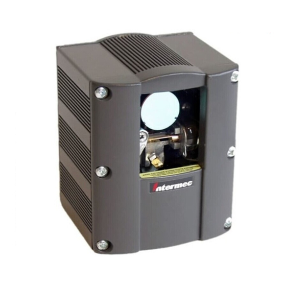
Page 1: Maxiscan 3300
Installation Guide P/N 3-530049-01 MaxiScan 3300 Fixed-position Scanner... -
Page 2: Regulatory Statements
The information contained in this document is for informational purposes only and is subject to change without notice. No part of this document may be copied or reproduced in any manner without the prior written permission of Intermec Technologies Corporation. - Page 3 Ausführung der Arbeitsabläufe entsteht gefährliches Laserlicht. ATTENTION – L’utilisation de contrôles/commandes ou de réglages ou l’exécution de procédures autres que ceux précisés par le présent document provoquent une lumière laser dangereuse. MaxiScan 3300 – Installation Guide – Edition 2.0...
- Page 4 MaxiScan 3300 – Installation Guide – Edition 2.0...
-
Page 5: Table Of Contents
1 Before you start ... 7 2 Installation ... 17 3 Connections ... 23 4 Input / output synchronization ... 27 MaxiScan 3300 – Installation Guide – Edition 2.0 Introduction ... 7 Checklist of items for your installation ... 7 Integration considerations ... 8 Location and reading position ... - Page 6 Host port passive current loop pinout ... 49 Synchros port pinout ... 50 Before you contact your Intermec representative ... 51 General reset of the MaxiScan 3300 ... 52 If you still need help ... 52 Reading distance (MaxiScan 3300 ST) ... 56 Reading distance (MaxiScan 3300 HR) ...
-
Page 7: Before You Start
This Installation Guide explains how to install and set up your MaxiScan 3300 in order to operate successfully in most working situations. You can use the EasySet setup software to set up the MaxiScan 3300. See Sec- tion 5— Setup for details. -
Page 8: Integration Considerations
The use of fixed barcode lengths and check digits increases reading ef ficiency and security. An external input synchronization device can be used to activate the MaxiScan 3300. This will ensure longer life for the motors and the laser diode, and allow you to detect unsuccessful read attempts. - Page 9 MaxiScan 3300: more depth of field If your application mostly needs a vertical beam, it is better to install the MaxiScan 3300 on its side, in order to ensure an optimal scan pattern: more depth of field...
-
Page 10: Location And Reading Position
• Reduces bar width and is much more critical for high-density barcodes • Reading may be possible with a pitch angle up to ± 70° • Reduce pitch to increase reading efficiency MaxiScan 3300 – Installation Guide – Edition 2.0 no read... - Page 11 • Reading may be possible with a skew angle up to ± 40° • Reduce skew to increase reading efficiency • A small skew angle (2–3° minimum) is necessary to prevent specular reflection MaxiScan 3300 – Installation Guide – Edition 2.0...
-
Page 12: Reading Moving Bar Codes
(scan width - code width) number of scans = pass-through speed scan width code width scan rate conveyor speed MaxiScan 3300 – Installation Guide – Edition 2.0 20 cm 10 cm 450 scans/sec 1 meter / sec (100 cm / sec) - Page 13 [ (2.5 * 450) / 100 ] - 2 = 9.25 so there will be 9 full scans on the code The code height value will vary slightly according to the degree of tilt and skew. MaxiScan 3300 – Installation Guide – Edition 2.0 ladder...
- Page 14 If we suppose that 5 scans is a good minimum, the formula becomes: code height x scan rate number of scans = pass-through speed Remain within the product specifications for reading distance and barcode density as prescribed in Section 8— Technical characteristics . MaxiScan 3300 – Installation Guide – Edition 2.0...
-
Page 15: Scan Angles
1 Before you start Scan angles MaxiScan 3300 – Installation Guide – Edition 2.0... -
Page 16: Scan Patterns
• cross pattern provides good coverage with codes with greater height than width circle sweep • suitable for labels on circular surfaces, such as CD-ROMs or tires MaxiScan 3300 – Installation Guide – Edition 2.0... -
Page 17: Installation
2 Installation Dimensions / mounting points / laser light plane 30 mm (1.2") 38 mm (1.5") 82 mm (3.2") 75 mm (2.9") 100 mm ° (3.9") 14 mm (0.5") ° MaxiScan 3300 – Installation Guide – Edition 2.0... -
Page 18: Optional Adjustable Stand
2 Installation Optional adjustable stand MaxiScan 3300 – Installation Guide – Edition 2.0... -
Page 19: Maxiscan Connection System (Mcs) Dimensions
2 Installation MaxiScan Connection System (MCS) dimensions MaxiScan 3300 – Installation Guide – Edition 2.0... -
Page 20: Rs-232 C Configuration
2 Installation RS-232 C configuration RS-232 C with synchronization configuration MaxiScan 3300 – Installation Guide – Edition 2.0... -
Page 21: Rs-422 / Rs-485 Configuration
2 Installation RS-422 / RS-485 configuration Passive current loop configuration MaxiScan 3300 – Installation Guide – Edition 2.0... -
Page 22: Maxiscan 3010 (Mns) Configuration
2 Installation MaxiScan 3010 (MNS) configuration The MaxiScan 3010 can be connected to the MaxiScan 3300 in two ways. The example below is taken from the MaxiScan 3010 Installation Guide . See the Guide for full details. MaxiScan 3300 – Installation Guide – Edition 2.0... -
Page 23: Connections
3 Connections MaxiScan 3300 pinout 15-pin subD female connector MaxiScan 3300 – Installation Guide – Edition 2.0... -
Page 24: Rs-232 C Pinout
3 Connections RS-232 C pinout I/O sync max current 20 mA 15-pin subD female connector MaxiScan 3300 – Installation Guide – Edition 2.0... -
Page 25: Rs-422 Pinout
RS-422 pinout I/O sync max current 20 mA MaxiScan 15-pin subD female connector MaxiScan 3300 – Installation Guide – Edition 2.0 RS-422: install resistor = user cable characteristic impedance between pins 1 and 3 host 15-pin subD male connector 3 Connections... -
Page 26: Rs-485 Pinout
MaxiScan 15-pin subD female connector RS-485: connect pins 1 and 2 and connect pins 3 and 4. Install resistor = user cable characteristic impedance between pins 1 and 3 host 15-pin subD male connector MaxiScan 3300 – Installation Guide – Edition 2.0... -
Page 27: Input / Output Synchronization
Reading can be triggered by an external device (opto-coupled cell, automated ma- chine, electrical control device) connected to pins 5 and 6. The MaxiScan 3300 can send a message to the host system when reading is activated by an input synchronization device. - Page 28 The output device operates when no current flows between SO+ and SO- (pins 7 and 8). The output device stops operating when the current starts to flow. An output trigger function (good read or no read) must be activated. MaxiScan 3300 – Installation Guide – Edition 2.0...
-
Page 29: Input / Output Configuration Examples
Note that the resulting "bouncing" phenomenon must be filtered either by the external system or by activating the "antibounce" parameter in EasySet. To find this parameter quickly, launch EasySet, select the MaxiScan 3300 product icon, deactivate the "Step-by-step mode", and select "antibounce" from the drop-down list in the search box. - Page 30 Current provided by the external input device must be limited to 20 mA max (15 mA is a good average value—choose a relay value <15 mA). An external power supply must be grounded with the MaxiScan 3300. In the example below, the VCC external power supply can be sourced on pin 10.
- Page 31 Current provided by the external input device must be limited to 20 mA max (15 mA is a good average value). An external power supply must be grounded with the MaxiScan 3300. In the example below, the VCC external power supply can be sourced on pin 10.
- Page 32 Note that the resulting "bouncing" phenomenon must be filtered either by the external system or by activating the "antibounce" parameter in EasySet. To find this parameter quickly, launch EasySet, select the MaxiScan 3300 product icon, deactivate the "Step-by-step mode", and select "antibounce" from the drop-down list in the search box.
- Page 33 Output synchronization—MCS connection unit—example 1 Relay-controlled output device Current provided by the external input device must be limited to 20 mA max (15 mA is a good average value—choose a relay value <15 mA). MaxiScan 3300 – Installation Guide – Edition 2.0...
- Page 34 4 Input / output synchronization Output synchronization—MCS connection unit—example 2 PLC-controlled output device Current provided by the external input device must be limited to 20 mA max (15 mA is a good average value). MaxiScan 3300 – Installation Guide – Edition 2.0...
-
Page 35: Setup
Online setup with slave mode commands EasySet System configuration software is the easiest way to set up your MaxiScan 3300. You can download your custom settings directly to the MaxiScan 3300 or print out and scan the corresponding configuration bar codes. -
Page 36: Online Setup With Easyset
"Automatic setup" in order to set the COM port parameters Refer to the EasySet online help for a detailed explanation of how to use the EasySet System configuration software. You can also set up your MaxiScan 3300 offline with bar codes printed from EasySet. -
Page 37: Basic Offline Setup
Basic offline setup You can set up your MaxiScan 3300 in a basic configuration by scanning configura- tion bar codes. Follow the instructions in this section. Basic setup does not include all the configuration possibilities of the MaxiScan. See Section 2— Installation to see other possible configurations. For a complete setup, use the EasySet System configuration software (see the preceding section Online setup with EasySet ). - Page 38 To deactivate the default one minute timeout, read the Continuous configuration mode bar code. When your configuration is complete, read the Configuration inhibit after 1 minute bar code. Continuous configuration mode Configuration inhibit after 1 minute Select interface RS-232 C MaxiScan 3300 – Installation Guide – Edition 2.0...
- Page 39 9600 baud (*) 19200 baud 7 data bits (*) 8 data bits Odd parity Even parity (*) No parity Postamble = Carriage Return Postamble = none Postamble = Carriage Return + Line Feed (*) MaxiScan 3300 – Installation Guide – Edition 2.0...
- Page 40 5 Setup Disable all symbologies Select symbologies Code 39 Code 128 / EAN 128 Test symbologies UPC-A, UPC-E, EAN-8, EAN-13 (UPC-A -> EAN-13) UPC-A, UPC-E, EAN-8, EAN-13 (UPC-A -> UPC-A) MaxiScan 3300 – Installation Guide – Edition 2.0...
-
Page 41: Online Setup With Slave Mode Commands
In this mode all setup commands can be sent directly to the MaxiScan 3300 through the RS-232 input port. To create a list of all the data strings you need, you must use the EasySet System configuration software provided on the CD-ROM. - Page 42 5 Setup MaxiScan 3300 – Installation Guide – Edition 2.0...
-
Page 43: Maxiscan Connexion System (Optional)
6 MaxiScan Connexion System (optional) The MaxiScan Connexion System (MCS) can be used to connect the MaxiScan 3300 to a host computer, power supply and synchronization device. The MCS is an optional accessory. Technical characteristics MaxiScan 3300 – Installation Guide – Edition 2.0... -
Page 44: Scanner Port Pinout
6 MaxiScan Connection System Scanner port pinout 15-pin subD male connector MaxiScan 3300 – Installation Guide – Edition 2.0... -
Page 45: Power Supply 7 To 25V Port Pinout
6 MaxiScan Connection System Power supply 7 to 25V port pinout 9-pin subD male connector MaxiScan 3300 – Installation Guide – Edition 2.0... -
Page 46: Host Port (Rs-232 C) Pinout
6 MaxiScan Connection System Host port (RS-232 C) pinout MCS 15-pin subD female connector MaxiScan 3300 – Installation Guide – Edition 2.0... -
Page 47: Host Port (Rs-422) Pinout
Host port (RS-422) pinout MCS 15-pin subD female connector MaxiScan 3300 – Installation Guide – Edition 2.0 6 MaxiScan Connection System RS-422: install resistor = user cable characteristic impedance between pins 1 and 3 host 15-pin subD male connector... -
Page 48: Host Port (Rs-485) Pinout
MCS 15-pin subD female connector RS-485: connect pins 1 and 2 and connect pins 3 and 4. Install resistor = user cable characteristic impedance between pins 1 and 3 host 15-pin subD male connector MaxiScan 3300 – Installation Guide – Edition 2.0... -
Page 49: Host Port Passive Current Loop Pinout
6 MaxiScan Connection System Host port passive current loop pinout Current Loop: connect pins 1 and 10 host 15-pin subD male connector MCS 15-pin subD female connector MaxiScan 3300 – Installation Guide – Edition 2.0... -
Page 50: Synchros Port Pinout
Synchros port pinout In all cases, the synchronization current provided by the external input/output device must be limited to 20 mA maximum (15 mA is a good average value). 9-pin subD female connector MaxiScan 3300 – Installation Guide – Edition 2.0... -
Page 51: Troubleshooting
(configuration inhibit after 1 minute selected) barcode length compatible with minimum / fixed length parameter settings of MaxiScan 3300 MaxiScan 3300 configured for check digit and no check digit present in code MaxiScan 3300 – Installation Guide – Edition 2.0... -
Page 52: General Reset Of The Maxiscan 3300
MaxiScan 3300, reconnect the MaxiScan 3300 power supply, and read the code: 4. Start up the EasySet System configuration software 5. Use EasySet System to download your complete setup to the MaxiScan 3300 (see Section 5— Setup ) If you still need help Contact your Intermec representative with full details of the problem. -
Page 53: Technical Characteristics
8 Technical characteristics c t i MaxiScan 3300 – Installation Guide – Edition 2.0 t u l t n i c i t i t - l c i t i r c ° 5 ± ° 4 ± ° 0... - Page 54 ) s l y t i g i l y t i : y t : y t MaxiScan 3300 – Installation Guide – Edition 2.0 ) l i ) l i , I I f i t ) "...
- Page 55 MaxiScan 3300 – Installation Guide – Edition 2.0 a l f 8 Technical characteristics...
-
Page 56: Reading Distance (Maxiscan 3300 St)
Reading distance (MaxiScan 3300 ST) This chart shows the horizontal reading range for the MaxiScan 3300 ST . The values shown are for high- contrast Code 39 with a ratio of 1:3 and correspond to the product default settings. Increased performance is possible with specific configuration setups. -
Page 57: Reading Distance (Maxiscan 3300 Hr)
Reading distance (MaxiScan 3300 HR) This chart shows the horizontal reading range for the MaxiScan 3300 HR for high density codes. The values shown are for high-contrast Code 39 with a ratio of 1:3 and correspond to the product default settings. -
Page 58: Accessories
8 Technical characteristics Accessories " " Y " " t t i n l l u c i t l a t t a l MaxiScan 3300 – Installation Guide – Edition 2.0 f i t...
Need help?
Do you have a question about the MaxiScan 3300 and is the answer not in the manual?
Questions and answers