
Related Manuals for ATIM Cloud Wireless ACW/SF8-WL-I


Summary of Contents for ATIM Cloud Wireless ACW/SF8-WL-I
- Page 1 Atim Cloud Wireless ® Leak detection User Guide Models concerned : ACW/SF8-WL-I ACW/LW8-WL-I ACW/SF8-WL-O ACW/LW8-WL-O...
-
Page 2: Table Of Contents
ABLE OF CONTENTS Version history of this document ............................3 Disclaimer ..................................3 Trademarks and copyrights ............................... 3 Declaration of conformity ..............................4 Environmental recommendations ............................. 4 Explosive atmosphere Environment Radio Technical specifications ..............................6 Strengths Technical specifications Water leakage detection sensor Housing.................................... - Page 3 Compatible configurator versions Configuration ................................... 18 Frame format .................................. 21 Quick start Alert frames ................................21 End of alerts frames ..............................21 Full frame detail Classic frame ................................22 Alert frame................................23 Frame of life ................................24 Test frame ................................24 Error frame ................................
-
Page 4: Version History Of This Document
Trademarks and copyrights ATIM radiocommunications®, ACW ATIM Cloud Wireless®, ARM Advanced Radio Modem® are registered trademarks of ATIM Sarl in France. Other trademarks mentioned in this document are the property of their respective owners. ATIM_ACW-WLL_UG_EN_V1.7... -
Page 5: Declaration Of Conformity
Declaration of conformity All ACW ATIM Cloud Wireless® products comply with the regulatory requirements of the R&TTE Directive 1999/5/EC Article 3: 1 Safety (Article 3.1a of Directive 1999/5/EC) NF EN60950-1 Ed. 2006/A1:2010/A11:2009/A12:2011 (health) EN62479:2010 (power <20mW) or EN62311:2008 (power > 20mW) 2 Electromagnetic compatibility (Article 3.1b of Directive 1999/5/EC) -
Page 6: Radio
Electrical hazard - If the instructions are not followed, there is a risk of electric shock and personal injury. Direct current symbol WARNING: Do not install near any heat or moisture. WARNING : for your safety, it is imperative that before any technical intervention on the equipment, it is switched off and not connected to the mains. -
Page 7: Technical Specifications
Technical specifications a. Strengths Reference WL-I WL-O (For the version with location option) Protection factor IP30 100 dB Buzzer + LED Flashes LED flashing Alert Built-in ¼ wave Built-in ¼ wave Antenna Water leak detection and/or location via cable Water leak detection and/or location via cable Cable b. -
Page 8: Water Leakage Detection Sensor
c. Water leakage detection sensor Typical value Location accuracy +/- 1m (For version with location option) Time needed for water to penetrate the cable (independent of the Reaction time +/- 5s reaction time of the whole product) ATIM_ACW-WLL_UG_EN_V1.7... -
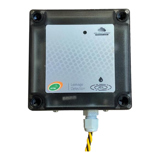
Page 9: Housing
ACW-WL-O label Each product of ATIM's ACW range has a QR Code label visible either on the side or on the front of the product. This QR code can be easily read with any 2D barcode reading application on smartphone. -
Page 10: Available Versions
Available versions a. Cables ATIM offers three cable versions to complement the ACW/WL: The CAB-WL is sold by the meter and is coupled to the ACW/WL. It allows the detection of water leakage. The CAB-WLL is sold by the meter and is coupled to the ACW/WL. It allows the detection and the localization of water leak. -
Page 11: Summary Of Cable Versions
c. Summary of cable versions Sensor cable for ACW/WL CAB-WL [€/metre of cable] Sensor cable for ACW/WL CAB-WLL with leakage location [€/meter of cable] Sensor cable for ACW/WL CAB-WLL-OIL (Oil, gasoline) [€/meter of cable] Connection cable between ACW/WLL and CAB-WLL-LEAD CAB-WLL-xx cables End of line plug to be connected to the last CAB-WLL-TERM... -
Page 12: Cable Installation
Cable installation a. Scheme NOTE Jumpers are cable extensions that are insensitive to the presence of water. WARNING Never loop the cable over itself or create contact points with conductive surfaces, as there is a risk of false positives! ATIM_ACW-WLL_UG_EN_V1.7... -
Page 13: Examples
b. Examples Cover an entire area Marginal area coverage Covering key points adapted to the global protection of prevent leaks from entering the key protection against major critical areas environment or spreading sources of leakage Mounting clip Adhesive cable Overhead piping Grouped with a Fixed with glue Under the HVAC... -
Page 14: Operation
Configuration mode: this mode is active 5 minutes after the exit of the deep sleep mode and authorizes the configuration of the product in Bluetooth thanks to the PC configurator or to the mobile application ATIM. During these 5 minutes messages are sent by radio every minute (5 "radio frames"), that allows you to check that the product works well, for example after having placed it under a cast iron manhole. -
Page 15: Putting The Product Into Service
b. Putting the product into service Unless otherwise requested, ACW products are delivered with batteries connected and set to "deep sleep" mode. To place the product in its operating mode, hold a magnet against the QRCODE label for 6 seconds. During these six seconds, the product's LED should blink WHITE and then... -
Page 16: Sending A Test Frame
Even if no network has been reached, it is assumed with this mode that an ATIM LoRa/LoRAWAN repeater located nearby will be able to repeat the Local frames emitted by the product in LoRAWAN frames on the network that the repeater has reached. -
Page 17: Operating Mode
f. Operating mode The ACW-WL sensor periodically measures the electrical resistance between its 2 electrodes, or the 2 strands of its cable to detect a possible presence of water at the time "t" and sends these data by radio on the Radio network (Sigfox or LoRa) in case of positive result. -
Page 18: Life Frame
g. Life frame These are issued either once a day or once every 4 days (configurable). NOTE By default, the period for sending life frames is set to once a day. h. Options A buzzer can be integrated in the sensor to emit an audible signal (100dB) in case of leak detection to signal an alert. i. -
Page 19: Acw Configurator
V5.2.2 or higher LoRaWAN : V0.0.1 Download and install the configuration software ''setupACW.exe'' at: https://www.atim.com/en/products-configurator/ Configuration The configuration is done via USB or Bluetooth. In the case of Bluetooth, you must restart the product, it should appear in the list of products on the home page of the configurator. Double click on it to open the ACW-WL configuration page. - Page 20 Threshold Threshold of detection allows to refine the measurements in certain configurations, it must be adjusted according to the measurement values received during the test and alert frames. During a measurement, the product measures the current leakage between the 2 strands of cables / electrodes, this value is compared to the Threshold value.
- Page 21 Number of retries Number of frames forwarding attempts in case of non-acquittal. NOTE By default, the Number of retries value is 5. Period between retries (hh:mm) Time period between these tests. NOTE By default, the Period between retries value is equal to 10 minutes. ATIM_ACW-WLL_UG_EN_V1.7...
- Page 22 Frame format a. Quick start Here are the usual frames encountered when using the ACW-WLL. If more details are needed or the received frame does not match the frames below, continue reading below. Test frames Sent when the product starts up, after it has been connected to the network: 0x854A0000xxxx With xxxx...
- Page 23 • Alert frame (threshold exceeded); New generation: These frames combine a classic frame and a measurement frame. They consist of a header warning that a threshold has been exceeded, followed by the samples of each channel for which a threshold has been exceeded. Classic frame Octet 1 –...
- Page 24 0x0c Reserved 0x0d Variable Alerts frames follow-up of the samples of the measurements of the channels in alert 0x0e General error - TBD (memory, ...) 0x0f Variable ... Sub-frame for ACW. Depending on the ACW Alert frame Byte 1 – In the lead Bit7 Bit6 Bit5...
- Page 25 The measurement type field is identical to that of the measurement frame. The xxxx sample that caused the alert is then inserted afterwards. Example: 0x8D4A0000xxxx Frame of life The life frame is sent at regular intervals according to the applied configuration (by default 4 days) and contains the battery levels of the product at no load (the product is doing nothing) and at load (the product is transmitting a radio frame).
- Page 26 Octet 2 – In the lead 0x4A Remaining bytes: Value measured on the sensor during the test. It must be close to zero (0x0000) if used with a cable or close to 0x6YY (YY any value) if used with electrodes. Error frame Octet 1 –...
- Page 27 The next byte identifies the nature of the error that occurred: Octet 3 – In the lead error message Error code Type of error Description 0x81 ERR_UNKNOWN 0x82 ERR_BUF_SMALLER The data table is full, impossible to write additional data ERR_DEPTH_HISTORIC_OUT_OF_RA The history depth is too large or too small for the frame 0x83 The number of samples is too large or too small for the...
- Page 28 0x93 ERR_KEEP_ALIVE_PERIOD Wrong structure of life frame period 0x94 ERR_ENTER_DEEP_SLEEP The product has gone into deep sleep mode 0x95 ERR_BATTERY_LEVEL_LOW Low battery level 0x96 ERR_ARM_TRANSMISSION A transmission was initialized but an error occurred 0x97 ERR_ARM_PAYLOAD_BIGGER Message size is too large for the network capacity 0x98 ERR_RADIO_PAIRING_TIMEOUT Unable to pair to a network before timeout...
- Page 29 Troubleshooting Radio data is not received • Check if the power supply is correctly connected to the modem • Check if the modem has been registered to the network • Check if network coverage is available • Check if the light is illuminated when transmitting Technical support For any further information or technical question, you can open a ticket on our technical support dedicated...
Need help?
Do you have a question about the Cloud Wireless ACW/SF8-WL-I and is the answer not in the manual?
Questions and answers