Table of Contents

Related Manuals for ATIM Cloud Wireless ACW/LW8-THAQ


Summary of Contents for ATIM Cloud Wireless ACW/LW8-THAQ
- Page 1 ATIM Cloud Wireless ® Temperature, Humidity and Air Quality sensor (CO2 & COV) User Guide Concerned models: ACW/LW8-THAQ ACW/SF8-THAQ ATIM Radiocommunications www.atim.com Chemin des Guillets info@atim.com 38250 Villard de Lans France...
-
Page 2: Table Of Contents
Table of contents DOCUMENT VERSION HISTORY ..............................4 DISCLAIMER ....................................4 TRADEMARKS AND COPYRIGHT ..............................4 DECLARATION OF COMPLIANCE ..............................5 ENVIRONMENTAL RECOMMENDATIONS ............................5 ................................5 XPLOSIVE ATMOSPHERE ................................... 5 NVIRONMENT ...................................... 6 ADIO TECHNICAL FEATURES................................. 7 ....................................7 RODUCT ................................... - Page 3 Error and alarm generic frame ..............................23 ................................25 XAMPLES OF FRAMES Measurement frame ................................25 Alert measurement frame ................................ 27 DOWNLINK ....................................28 .) ..............28 ONFIGURATION OF THE FRAME PARAMETERS SENDING PERIOD NUMBER OF SAMPLES ................................28 ENSORS ACTIVATION ..............................
-
Page 4: Document Version History
Trademarks and copyright ATIM radiocommunications®, ACW ATIM Cloud Wireless® and ARM Advanced Radio Modem® are registered trademarks of ATIM SARL in France. The other trademarks mentioned in this document are the property of their respective owners. ATIM_ACW-THAQ_UG_EN_V1.2... -
Page 5: Declaration Of Compliance
Declaration of compliance All ACW Atim Cloud Wireless® products comply with the regulatory requirements of the R&TTE Directive (1999/5/EC), article 3: 1 SAFETY (Article 3.1a of the 1999/5/EC Directive) NF EN60950-1 Ed. 2006/A1:2010/A11:2009/A12:2011 (health) EN62479: 2010 (power <20mW) or EN62311:2008 (power > 20mW) 2 Electromagnetic compatibility (Article 3.1b of the 1999/5/EC Directive) -
Page 6: Radio
General hazard – Failure to follow the instructions presents a risk of equipment damage. Electrical hazard – Failure to follow the instructions presents a risk of electrocution and physical injury. Direct-current symbol WARNING: do not install this equipment near any source of heat or any source of humidity. WARNING: for your safety, it is essential that this equipment be switched off and disconnected from mains power before carrying out any technical operation on it. -
Page 7: Technical Features
Technical features a. Product Dimensions 80 x 80 x 35 mm Antenna Integrated (¼ d’of wave) -40°C to +125°C (operation) Temperature -40°C to+150°C (storage) Mounts to Wall Casing Indoor Power supply 1 battery-pack [7,2 Ah] Weight 200 g Frequency 863 – 870 MHz Power 25 mW (14 dBm) Sigfox : 100 bits/s... - Page 8 Range 0 – 500 VOC index Resolution The VOC index represents the overall concentration of all VOCs (volatile organic compounds) and not a specific concentration of a given compound. The index is defined on a scale from 0 to 500 (0 for almost zero VOC concentration and 500 for very high VOC concentration).
-
Page 9: Casing
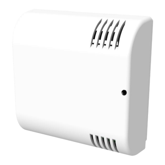
Casing a. Space requirements <- Orifices de -> fixations b. Mounts to ACW-THI modems are attached to a wall with two screws that fit into the two mounting holes on the back of the box. The vents on the cover must be on the right, in the same direction as the photo opposite. -
Page 10: Installation
c. Installation For best results, it is recommended to install the box without environmental obstruction and to place it at a minimum height of 2m. For information, the antenna is integrated into the box. It must be mounted on a vertical support, or fixed to a wall. -
Page 11: Operation
Operation a. Operating mode The operating of the ACW-THAQ is divided between different modes: Operating mode: this is the default mode when starting the product. In this mode, the module periodically sends measurements according to the configuration applied (if the product has never been configured, the factory configuration applies, see Factory settings). -
Page 12: Product Start-Up
b. Product start-up In most cases, the ACW-THAQ is started up before delivery (battery packs already connected) and then placed in deep standby to limit consumption. To place the product in its operating mode, bring a magnet close to the diamond-shaped marking on the box for 6 seconds. -
Page 13: Radio Module Activity
e. Radio module activity Any sending of a radio frame is indicated by three brief GREEN flashes of the LED. f. Threshold exceeded When thresholds have been configured using the configurator and the measurement values exceed these thresholds, the product LED emits a periodic ORANGE flash to notify it. -
Page 14: Acw Configurator
LoRaWAN: V0.0.1 Download and install the configuration software setup ’setupACW.exe‘ at: https://www.atim.com/en/support-2/downloading/ Notes: The product must be in its Configuration mode to be able to be detected by the configurator. To do this, you must first put the product into deep standby mode (magnet close to 6 seconds), wait about twenty seconds for the entry into deep standby to take effect, then wake up the product (magnet 6 seconds to new). -
Page 15: Acw-Thaq Setup
b. ACW-THAQ setup Emission and sampling period of the frame The transmission period (1) corresponds to the time interval between each sending of a measurement frame. This period can be configured from 10 min to 255 h and its default value is 1 hour. In addition, it is possible to configure the number of samples in a frame (2). -
Page 16: Frame Timestamp
Frame timestamp It is possible to deactivate / activate the time stamping of all radio frames (5). WARNING: This option when activated monopolizes 4 bytes in the frame which cannot be used for useful data. Configuration of the Radio module The radio module can be configured to pair with a network (Sigfox or LoRaWAN) or to operate in local (or point-to- point) mode (6). -
Page 17: Air Quality
Air quality Two sensors are present for the quality measurement: a first for the measurement of the CO2 concentration, the second for the measurement of VOCs (Volatile Organic Compounds). For each one, you will find the following configuration elements: Enabling/disabling of the sensor. High and Low thresholds configuration. -
Page 18: Factory Settings
c. Factory settings Radio frames settings: Radio frame emission period: 10 minutes Number of samplings: 1 History depth: 1 General settings: Keep alive frame emission period: 4 days Timestamp: disabled Sensors’ settings: Temperature & humidity State: enabled Temperature threshold: disabled Humidity threshold: disabled Air quality sensor State: enabled... -
Page 19: Frames Format
Frames format a. Sigfox and LoRaWAN Uplink frame Byte 1 Byte 2 . . . Byte n Frame-header Frame-specific data We can differentiate three types of frames: ⚫ Classic frame; New generation: Very close to the old frames, the difference is that you can activate the timestamp. -
Page 20: Measurement
Different frames’ type Frame type Size of data Descriptions 0x00 Reserved 0x01 5 bytes Keep alive frame 0x02 0 byte Downlink request for network testing (Only Sigfox) 0x03 8 bytes Reserved 0x04 Reserved 0x05 1 byte Test frame with counter 0x06 Variable (Cfg box) Response to a setup frame. -
Page 21: Alert Measurement Frame
Type of possible measure: Measure type Unit Data size Data type Descriptions 0x08 c°C 2 bytes (Big Endian - Entier signé Temperature in hundredth of Celsius Degree MSB) ➢ Resolution: 0.01°C ➢ Max value: 125°C ➢ Min value: -40°C 0x09 2 bytes (Big Endian - Entier signé... -
Page 22: Keep Alive Frame
For each of the channels in alert a header is inserted and is constituted as follows: Channel Header Bit7 Bit6 Bit5 Bit4 Bit3 Bit2 Bit1 Bit0 Alert type Number of the channel Measurement type The type of alert field is used to identify whether it is a breach of the high threshold, the low threshold, or a return between the thresholds. -
Page 23: Error And Alarm Generic Frame
Error and alarm generic frame Byte 1 - Header Bit7 Bit6 Bit5 Bit4 Bit3 Bit2 Bit1 Bit0 Timestamp Measurement Reserved Error frame generation frame = 0x0e If the Timestamp is activated, 4 bytes with the Timestamp value will be preceded by the header (byte 1). For each error message, a header is inserted and is formed as follows: Error frame header Bit7... - Page 24 0x91 ERR_RADIO_QUEUE_FULL Radio queue is full 0x92 ERR_CFG_BOX_INIT_FAIL Error during black box initialization 0x93 ERR_KEEP_ALIVE_PERIOD Wrong keep alive frame structure 0x94 ERR_ENTER_DEEP_SLEEP The device entered deep sleep mode 0x95 ERR_BATTERY_LEVEL_LOW Low battery 0x96 ERR_ARM_TRANSMISSION A transmission has been initiated but an error has occurred 0x97 ERR_ARM_PAYLOAD_BIGGER Message size is too large for the capacity of the network...
-
Page 25: Examples Of Frames
b. Examples of frames Measurement frame With disabled timestamp, there is no historic and the sampling number is 1 (Temperature and humidity exclusively): Byte 1 Byte 2 Byte 3 Byte 4 Byte 5 Byte 6 Byte 7 0xA0 0x08 0x09 (new generation (channel 0, measurement... - Page 26 Now with a sampling number of 2: Byte Byte Byte Byte Byte Byte Byte Byte Byte 1 Byte 2 Byte 3 Byte 8 0xA0 0x003C 0x08 0x01 0x2C 0x08 0xA4 0x09 0x22 0x13 0x17 0xDE (new generation (emission period) (channel 0, (channel 0, measurement frame, measurement...
-
Page 27: Alert Measurement Frame
Alert measurement frame a high threshold being exceeded on channel 1 (virtual probe), the frame will be: Byte 1 Byte 2 Byte 3 Byte 4 0x8D 0x58 0x02 0xC9 (new generation alert frame) (exceeding high threshold channel 1, temperature measurement) The sampling that triggered the higher threshold deals with 0x02C9 (7.13 °C) ATIM_ACW-THAQ_UG_EN_V1.2... -
Page 28: Downlink
The operation of the Downlink is explained in the document ATIM_ACW-DLConfig_UG_FR_v1.4, relating to version V1.2.0 of the ATIM Downlink Protocol (see this document for all parameters and commands common to all products). The parameters specific to ACW-THAQ are as follows: a. -
Page 29: Threshold Configuration
c. Threshold configuration Parameter code Byte 2 Byte 3 Byte 4 Byte 5 Byte 6 Byte 7 Byte 8 Byte 9 Byte Byte (Byte 1) 0xD6 0x09 0x00 High threshold threshold Hysteresis Durée Thresh (temperature value value old Tx threshold) 0xD7 (humidity threshold) 0xDA... -
Page 30: Coefficient
Coefficient Parameter code (Byte 1) Byte 2 Byte 3 0x59 (temperature Value coefficient) The multiplication coefficient is represented by the "Value" field in the table above. The coefficient value must be sent in Little Endian encoding and can be between 0 and 10,000 (this value is divided by 1000 by the product). Example: For a coefficient of 0,1, the sent value will be 100 = 0x6400. -
Page 31: Reserved Codes For Futures Software Evolutions
g. Reserved codes for futures software evolutions Parameter code (Byte 1) Parameter value (Byte 2) 0x10 0x08 0x11 0x00 WARNING : DO NOT MODIFY THESE VALUES ATIM_ACW-THAQ_UG_EN_V1.2... -
Page 32: Technical Support
Technical support For any information or technical problems, you can contact our technical support: https://www.atim.com/en/technical-support/ ATIM_ACW-THAQ_UG_EN_V1.2...
Need help?
Do you have a question about the Cloud Wireless ACW/LW8-THAQ and is the answer not in the manual?
Questions and answers