Table of Contents
Advertisement
Quick Links
Advertisement
Table of Contents

Related Manuals for ATIM Cloud Wireless TM P Series


Summary of Contents for ATIM Cloud Wireless TM P Series
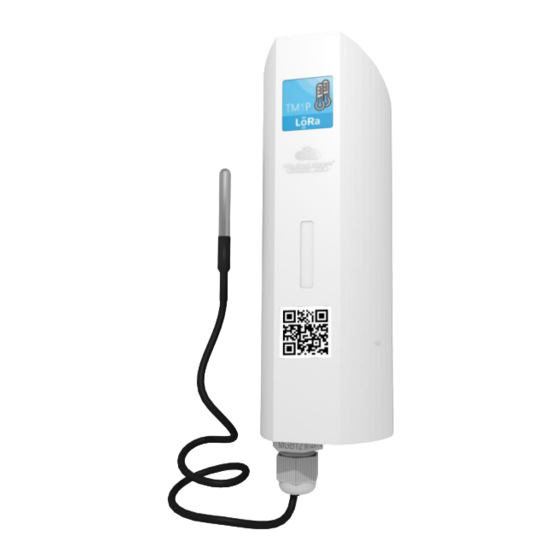
- Page 1 ATIM Cloud Wireless Temperature monitoring through RTD TMxP User Guide Concerned models: ACW/LW8-TM1P ACW/LW8-TM2P ACW/LW8-TM0P ACW/SF8-TM1P ACW/SF8-TM2P ACW/SF8-TM0P ATIM Radiocommunications www.atim.com Chemin des Guillets info@atim.com 38250 Villard de Lans France...
-
Page 2: Table Of Contents
Table of contents DOCUMENT VERSION HISTORY ................................4 DISCLAIMER ......................................5 TRADEMARKS AND COPYRIGHT ................................5 DECLARATION OF COMPLIANCE ................................5 ENVIRONMENTAL RECOMMENDATIONS ............................5 ..................................5 XPLOSIVE ENVIRONMENT ....................................5 NVIRONMENT ........................................ 6 ADIO TECHNICAL SPECIFICATIONS................................7 ......................................7 RODUCT .................................... - Page 3 Alert frame ......................................24 Keep-alive frame ....................................25 Error and alarm generic frame ................................. 25 ..................................27 XAMPLES OF FRAMES Measuring frame ....................................27 Alert measurement frame ................................28 DOWNLINK ......................................29 .) ..............29 ONFIGURATION OF THE FRAME PARAMETERS SENDING PERIOD NUMBER OF SAMPLES ..................................
-
Page 4: Document Version History
This user guide applies to the below product versions Product version Product references (Visible on the product label) LoRaWAN ACW/LW8-TMxP Sigfox ACW/SF8-TMxP Document version history Version Date Description Author Affects software version 02/01/2020 Document creation V0.0.1 05/03/2020 Corrections V0.0.1 11/03/2020 Probe wiring addition V0.0.1 25/03/2020... -
Page 5: Disclaimer
® ® ATIM, ACW ATIM Cloud Wireless and ARM Advanced Radio Modem are registered trademarks of ATIM SARL in France. The other trademarks mentioned in this document are the property of their respective owners. Declaration of compliance ® All ACW Atim Cloud Wireless products comply with the regulatory requirements of the R&TTE Directive... -
Page 6: Radio
General hazard – Failure to follow the instructions presents a risk of equipment damage. Electrical hazard – Failure to follow the instructions presents a risk of electrocution and physical injury. WARNING: do not install this equipment near any source of heat or any source of humidity. WARNING: for your safety, it is essential that this equipment be switched off and disconnected from mains power before carrying out any technical operation on it. -
Page 7: Technical Specifications
Technical specifications a. Product Dimensions 154 x 54 x 54 mm Antenna Integrated (¼ wave) Temperature probes 1 or 2 analog probes PT100 or PT1000 -25°C à +70°C (operating) Temperature -40°C à +70°C (storage) Mounts to Wall, tube or mast, DIN-Rail Casing IP 65 Power Supply... -
Page 8: Housing
Housing a. Space requirements Maximum cable diameter through cable gland: 7mm ATIM_ACW-TMxP_UG_EN_V1.0... -
Page 9: Mounting To A Support
b. Mounting to a support ACW modems can be mounted on a flat wall, a tube or pole or a DIN rail, depending on the type of installation you require. These three types of support frames attach to the rear of the housing. Mounting on a flat wall (provided): Mounting on flat wall (provided) Installation on a tube... -
Page 10: Opening The Acw Housing
d. Opening the ACW housing The housing must be opened to access both the terminal block and the mini- USB port used to configure the module. To do this, insert a screwdriver into the slot and tilt it downward to lift the inside tab (see photo). -
Page 11: Wiring Of The Probes
f. Wiring of the probes 3 wires probe Probe 2 – A Probe 2 - A Probe 2 - B Probe 1 – A Probe 1 - A Probe 1 – B T° T° 2 wires probe Probe 2 - A Probe 2 - B Probe 1 - A Probe 1 - B... -
Page 12: Operating
Operating a. Operating mode The operating of the ACW-TMxP deals with several modes: Exploitation mode: this is the default mode when starting the product. In this mode, the module periodically sends measurements according to the configuration applied (if the product has never been configured, the factory configuration applies, cf. -
Page 13: Product Start Up
Even if no network has been reached, it is assumed with this mode that an ATIM LoRa / LoRaWan repeater located nearby will be able to repeat the Local frames sent by the product in LoRaWan frame on the network that the repeater will have joined. -
Page 14: Test Frame Emission
c. Test frame emission When the product is in its operating mode (and only in this mode), it is possible to send a test frame (which avoids waiting for the next measurement frame) including a measurement sample. To do this, simply bring the magnet closer until the GREEN light signal goes out. -
Page 15: Battery Passivation
i. Battery passivation The ACW-TMXP incorporates a battery depassivation feature, to limit the phenomenon of battery passivation during prolonged phases of deep standby. This feature is automatically activated as soon as the product goes into its deep sleep mode. The product will then wake up once a day to start the battery depassivation sequence, then the product will automatically return to deep standby. -
Page 16: Acw Configurator
V5.0.1 or later LoRaWAN: V0.0.1 Download and install the configuration software setup “setupACW.exe” at: https://www.atim.com/en/downloading/ When the ACW Configurator is launched, the waiting Click on "Help" at the top left of the window then on window appears on the screen. -
Page 17: Configuration Of The Acw-Tmxp
b. Configuration of the ACW-TMxP Emission period and samples in the frame The transmission period (1) corresponds to the time interval between each sending of a measurement frame. This period can be configured from 10 min to 255 h and its default value is 1 hour. In addition, it is possible to configure the number of samples in a frame (2). -
Page 18: Frame Timestamp
Compatibility mode with the ATIM FSK / Sigfox Repeater: This mode should be selected when you want to operate in Sigfox, but the network is not accessible. This mode, associated with the ATIM FSK / Sigfox Repeater, then makes it possible to join the Sigfox network through this repeater. In this mode,... -
Page 19: Product's Clock
the product transmits these frames both on the Sigfox network and in Local (FSK modulation). The FSK / Sigfox repeater then relays these frames on the Sigfox network (The repeater must be placed in a location where the Sigfox network is accessible). Important note: If the product has access to the Sigfox network, the default operating mode (Sigfox) must be used. -
Page 20: Validation The Configuration
Validation the configuration After having filled all the configuration parameters, it is imperative to click on the button "Apply to ACW" to send the configuration to the product (12). It is also possible at any time to read the current configuration of the product which will update the parameters on the configurator or to reset the default configuration of the product. -
Page 21: Update Of Acws
d. Update of ACWs When connected with Bluetooth Low Energy to the product, it is possible to update the different software that composes it. To do this, go to the menu Tools->Updater (CTRL+U ATIM_ACW-TMxP_UG_EN_V1.0... -
Page 22: Frames Format
Frames format a. Sigfox and LoRaWAN Uplink frame Byte 1 Byte 2 . . . Byte n Frame header Frame specific data We can differentiate three types of frames: ⚫ Classic frame; New generation: Very similar to the old frames, the difference is that you can activate the timestamp. -
Page 23: The Different Type Of Frames
The different type of frames Type of frame Data size Descriptions 0x00 Reserved 0x01 4 bytes Keep alive frame 0x02 0 bytes Downlink request for network testing 0x03 Reserved 0x04 Reserved 0x05 1 byte Teste frame with counter 0x06 Variable (Cfg box) Answer to a configuration frame 0x07 Variable... -
Page 24: Alert Frame
In the case of ACW-TMxP, the type of measurement can take three values: • 1 in decimal (0x01 in hexadecimal) for the input state. • 4 in decimal (0x04 in hexadecimal) for a counting channel. • 8 in decimal (0x08 in hexadecimal) for a temperature channel. A temperature measurement will be expressed in hundredths of °... -
Page 25: Keep-Alive Frame
The type of alert field is used to identify whether it is a breach of the high threshold, the low threshold or a return between the thresholds. WARNING: A threshold alert can only be triggered by a temperature channel. These values are defined as follows: Value Description 0x00... - Page 26 For each error message, a header is inserted and is formed as follows: Error frame header Bit7 Bit6 Bit5 Bit4 Bit3 Bit2 Bit1 Bit0 Message index Length of the error frame The message index field is used to prioritize messages when several errors occur. The length of the error message field indicates the size in bytes of the error message.
-
Page 27: Examples Of Frames
0x9B ERR_SENSORS_FAIL The sensor has stopped to operate 0x9C ERR_BOX_OPENED Casing opening 0x9D ERR_BOX_CLOSED Casing closing Only codes 0x8A and 0x95 are followed by additional data corresponding to the battery level in millivolts. This value is coded in two bytes, the most significant byte first (MSB) Warning: for codes ranging from 0x81 to 0x92, the product will enter its FAULT mode and will no longer perform its measurement function. -
Page 28: Alert Measurement Frame
Here is an example of a frame with the input configured as a counter (1 sample, no history): Octet 1 Octet 2 Octet 3-6 Octet 7 Octet Octet 9 Octet 10 Octet Octet 0xA0 0x04 0x0000001 0x08 0x08 0x85 0x18 0x08 0x50 (channel... -
Page 29: Downlink
The operation of the Downlink is explained in the document ATIM_ACW-DLConfig_UG_FR_v1.4, relating to version V1.2.0 of the ATIM Downlink Protocol (see this document for all parameters and commands common to all products). The parameters specific to ACW-TMxP are as follows: a. -
Page 30: Type Of Probes
c. Type of probes Parameter code (Byte 1) Parameter value (Byte 2) 0x18 0xYZ This parameter identifies if the characteristic of the probe (PT100 or PT1000) Field Z corresponds to probe 1 and field Y corresponds to probe 2. The possible values for these fields are: 1 =>... -
Page 31: Reserved Codes For Futures Evolutions
g. Reserved codes for futures evolutions Parameter code (Byte 1) Parameter value (Byte 2) 0x10 0x08 0x11 0x00 WARNING: DO NOT CHANGE THESE VALUES ATIM_ACW-TMxP_UG_EN_V1.0... -
Page 32: Technical Support
Technical support Contact our technical support team by email with any questions or technical problems you may have: https://www.atim.com/en/technical-support/ ATIM_ACW-TMxP_UG_EN_V1.0...
Need help?
Do you have a question about the Cloud Wireless TM P Series and is the answer not in the manual?
Questions and answers