Table of Contents

Related Manuals for ATIM Cloud Wireless MR4


Summary of Contents for ATIM Cloud Wireless MR4
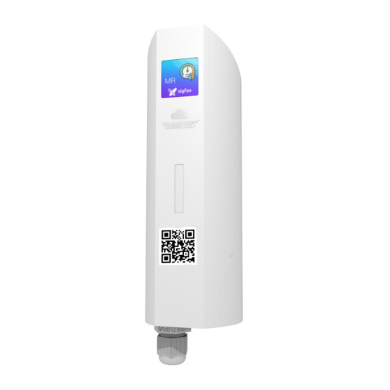
- Page 1 ATIM Cloud Wireless Metering and Dry contacts inputs User Guide Concerned models: ACW/SF8-MR4 ACW/LW8-MR4 ATIM Radiocommunications www.atim.com Chemin des Guillets info@atim.com 38250 Villard de Lans +33 4 76 95 50 65 France...
-
Page 2: Table Of Contents
Table of contents THIS USER GUIDE IS APPLICABLE TO THE FOLLOWING REFERENCES ....................4 DOCUMENT VERSION HISTORY ..............................4 DISCLAIMER ....................................5 TRADEMARKS AND COPYRIGHT ..............................5 DECLARATION OF COMPLIANCE ..............................6 ENVIRONMENTAL RECOMMENDATIONS ............................6 ..................................6 XPLOSIVE ATMOSPHERE .................................... - Page 3 WAN ................................22 IGFOX AND Classic frame..................................... 22 Measurement frame ................................. 23 Alert measurement frame ................................. 24 Keep alive frame ..................................25 Error and alarm generic frame ..............................25 MR4 specific frame ................................... 27 ................................28 XAMPLES OF FRAMES Measurement frame ................................. 28 Alert measurement frame .................................
-
Page 4: This User Guide Is Applicable To The Following References
This user guide is applicable to the following references Product version Product references (Visible on the label of the product) LoRaWAN ACW/LW8-MR4 Sigfox ACW/SF8-MR4 Document version history Version Date Description Author Software version 23/01/2020 Document creation V0.0.1 28/02/2020 Current consumption addition V0.0.1 05/03/2020 Correction... -
Page 5: Disclaimer
Trademarks and copyright ATIM radiocommunications®, ACW ATIM Cloud Wireless® and ARM Advanced Radio Modem® are registered trademarks of ATIM SARL in France. The other trademarks mentioned in this document are the property of their respective owners. ATIM_ACW-MR4_UG_EN_V0.9.docx... -
Page 6: Declaration Of Compliance
Declaration of compliance All ACW Atim Cloud Wireless® products comply with the regulatory requirements of the R&TTE Directive (1999/5/EC), article 3: 1 SAFETY (Article 3.1a of the 1999/5/EC Directive) NF EN60950-1 Ed. 2006/A1:2010/A11:2009/A12:2011 (health) EN62479: 2010 (power <20mW) or EN62311:2008 (power > 20mW) 2 Electromagnetic compatibility (Article 3.1b of the 1999/5/EC Directive) -
Page 7: Radio
General hazard – Failure to follow the instructions presents a risk of equipment damage. Electrical hazard – Failure to follow the instructions presents a risk of electrocution and physical injury. Direct-current symbol WARNING: do not install this equipment near any source of heat or any source of humidity. WARNING: for your safety, it is essential that this equipment be switched off and disconnected from mains power before carrying out any technical operation on it. -
Page 8: Prelude
Prelude This user guide describes the ATIM ACW-MR products functionalities. It explains operating, configuration and installation modes in functions of different use cases. ACW-MR Product line ACW-MR product line regroups different types of radio equipment which allow pulse metering, bang-bang control and fraud detection. - Page 9 CAPT-ILS1 In addition to the ACW-MR4, there is an industrial detector opening/closing door/window/trap. Coupled with an ACW-MR4, it comes wired and preconfigured for immediate installation. This sensor is generally used for intrusion detection. It is also suitable for monitoring Skydome openings or for checking the presence of objects in their parking area.
-
Page 10: Technical Specifications
Technical specifications Product Dimensions 154 x 54 x 54 mm Antenna Integrated (1/4 of wave) -25°C to +70°C (Operating mode) Temperature -40°C to +70°C (Storage) Mounts to Wall, tube or mast, DIN-Rail Casing IP 65 Power Supply 2x packs of Lithium AA batteries Weight 300 g Frequency... -
Page 11: Casing
Casing Footprint Maximum diameter of the cable in the stuffing box: 7 mm. ATIM_ACW-MR4_UG_EN_V0.9.docx... -
Page 12: Fasteners
Fasteners ACW modems are fixed on a flat wall, a mast or on a DIN rail depending on the type of installation desired. These three types of fasteners are plugged into the back of the case. Fixing on a flat wall (supplied): On tube or mast: DIN rail mounting: Product Identification... -
Page 13: Installation And Dismantling
Installation and dismantling It is necessary to open the box to access on the one hand the micro-USB port allowing the configuration of the module and on the other hand to the connection terminal block. To do this, you must insert the screwdriver into the slot and tilt it downwards to lift the internal tab (see photo opposite). -
Page 14: Connector Mapping
Connector Mapping The connector mapping is as follows: WIRECUT ATIM_ACW-MR4_UG_EN_V0.9.docx... -
Page 15: Operating
Operating Operating modes The operating of the ACW-MR4 is divided between different modes: Operating mode: this is the default mode when starting the product. In this mode, the module periodically sends measurements according to the configuration applied (if the product has never been configured, the factory configuration applies, see Factory settings). -
Page 16: Product Start-Up
Product start-up In most cases, the ACW-MR4 is started up before delivery (battery packs already connected) and then placed in deep standby to limit consumption. To place the product in its operating mode, bring a magnet close to the diamond-shaped marking on the box for 6 seconds. -
Page 17: Radio Module Activity
During these six seconds, the product led will flash in the color corresponding to the operating mode, then the end of the sequence will be indicated by a fade acknowledging that the product has been put on standby. WHITE The magnet can therefore be removed. Radio module activity Any sending of a radio frame is indicated by three brief GREEN... -
Page 18: Acw Configurator
Sigfox: V0.0.1 V5.0.1 LoRaWAN: V0.0.1 Download and install the configuration software setup ’setupACW.exe‘ at: https://www.atim.com/en/support-2/downloading/ When the ACW Configurator is launched, the waiting Click on "Help" at the top left of the window then on window appears on the screen. -
Page 19: Acw-Mr4 Setup
ACW-MR4 setup Emission period and samples in the frame The transmission period (1) corresponds to the time interval between each sending of a measurement frame. This period can be configured from 10 min to 255 h and its default value is 1 hour. In addition, it is possible to configure the number of samples in a frame (2). -
Page 20: Frame Timestamp
Frame timestamp It is possible to deactivate / activate the time stamping of all radio frames (5) WARNING: This option when activated monopolizes 4 bytes in the frame which cannot be used for useful data. Product clock If the time stamping function is activated, it is essential to configure the internal clock of the product from the configurator, which will retrieve the system clock from the computer to apply it to the product (6). -
Page 21: Factory Settings
Factory settings Radio frames settings: Radio frame emission period: 10 minutes Number of samplings: 1 History depth: 1 General settings: Keep alive frame emission period: 4 days Timestamp: disabled Sensors parameters: Inputs 1 and 2 deal with meter 1 and meter 2 respectively Pull up “+”... -
Page 22: Frames Format
Frames format Sigfox and LoRaWAN Uplink frame Byte 1 Byte 2 . . . Byte n Frame header Frame-specific data We can differentiate three types of frames: ⚫ Classic frame; New generation: Very close to the old frames, the difference is that you can activate the timestamp. -
Page 23: Measurement Frame
Different type of frames: Frame type Size of data Descriptions 0x00 Reserved 0x01 5 bytes Keep alive frame 0x02 0 byte Downlink request for network testing (Only Sigfox) 0x03 8 bytes Reserved 0x04 Reserved 0x05 1 byte Test frame with counter 0x06 Variable (Cfg box) Response to a setup frame. -
Page 24: Alert Measurement Frame
For each channel, a header is inserted afterwards and is constituted as follows: Channel header Bit7 Bit6 Bit5 Bit4 Bit3 Bit2 Bit1 Bit0 Reserved Numbers of channel Type of measurement In the case of ACW-MR4, the measurement type can be worth 0x01 for the state of the inputs or 0x04 for the value of a counter. -
Page 25: Keep Alive Frame
These values are defined as follows: Value Description 0x00 In between thresholds 0x01 Exceeding the high threshold 0x02 Exceeding the low threshold 0x03 Reserved The measurement type field is here identical to that of the measurement frame (ie 0x04 in hexadecimal for the ACW- MR4). - Page 26 For each error message, a header is inserted and is formed as follows: Error frame header Bit7 Bit6 Bit5 Bit4 Bit3 Bit2 Bit1 Bit0 Index of message Error message length The message index field is used to prioritize messages when several errors occur. The length of the error message field indicates the size in bytes of the error message.
-
Page 27: Mr4 Specific Frame
0x97 ERR_ARM_PAYLOAD_BIGGER Message size is too large for the capacity of the network 0x98 ERR_RADIO_PAIRING_TIMEOUT Impossibility to pair to a network within the fixed period 0x99 ERR_SENSORS_TIMEOUT A timeout has been reached out on the sensor 0x9A ERR_SENSOR_STOP The sensor did not report a value after reading 0x9B ERR_SENSORS_FAIL The sensor has stopped to operate... -
Page 28: Examples Of Frames
Examples of frames Measurement frame 1 counter input (counter 1) and 1 edge detection input (input 2), without time stamp, no history and a sample number of 1. Byte 1 Byte 2 Byte 3 Byte 4 Byte 5 Byte 6 Byte 7 Byte 8 0xA0... -
Page 29: Downlink
The operation of the Downlink is explained in the document ATIM_ACW-DLConfig_UG_FR_v1.4, relating to version V1.2.0 of the ATIM Downlink Protocol (see this document for all parameters and commands common to all products). The parameters specific to ACW-MR4 are as follows: Configuration of the frame parameters (sending period, number of samples, etc.) -
Page 30: Threshold Counters Setup
Bits 5,4 (BB) => choice of draw resistance: pull up - BB = 1; pull down – BB = 2. Bits 2-0 (CCC) => choice of input mode: Front detection - CCC = 1; counter 1 - CCC = 2; counter 2 - CCC = 3;... -
Page 31: Technical Support
Technical support For any information or technical problems, you can contact our technical support: https://www.atim.com/en/support-2/technical-support/ ATIM_ACW-MR4_UG_EN_V0.9.docx...
Need help?
Do you have a question about the Cloud Wireless MR4 and is the answer not in the manual?
Questions and answers