
Related Manuals for AmeriWater 00HC-4090


Summary of Contents for AmeriWater 00HC-4090
- Page 1 Operation & Maintenance Manual Laboratory Storage Tank 3345 Stop 8 Rd, Dayton, OH 45414 | 800 535 5585 | www.ameriwater.com 98-0123 Rev E Manufactured With Pride in the USA...
-
Page 3: Table Of Contents
TABLE OF CONTENTS LAB STORAGE TANKS TABLE OF CONTENTS TABLE OF CONTENTS ......................... 1 THEORY OF OPERATION ..................... 3 Models ..........................3 Dimensions .......................... 4 Performance ........................4 Electrical Safety and Supply Requirements ................4 COMPONENT IDENTIFICATION ..................5 Flow Schematic ........................7 INSTALLATION ........................ - Page 4 TABLE OF CONTENTS LAB STORAGE TANKS 12.4 Resistivity Controller Replacement ..................28 WARRANTY ........................30 CALIFORNIA PROPOSITION 65 ....................31 98-0123 Rev E...
-
Page 5: Theory Of Operation
Please read the Operation Manual before operating or servicing the system. Contact AmeriWater Customer Service with any questions at 1-800-535-5585 Monday through Friday 8:00 a.m. to 5:00 p.m. eastern standard time. For after-hours emergencies follow the instructions on the recorded message. -
Page 6: Dimensions
Please note that spatial dimensions are at nominal and may vary during installation. Variation with rotating components (i.e., tank vent filters) has been taken into consideration. Models Height (ins) Width (ins) Depth (ins) 00HC-4090 62.75 +/- 12 33.25 00HC-4092 70+/- 12 44.75 40 +/- 6 1.3 Performance... -
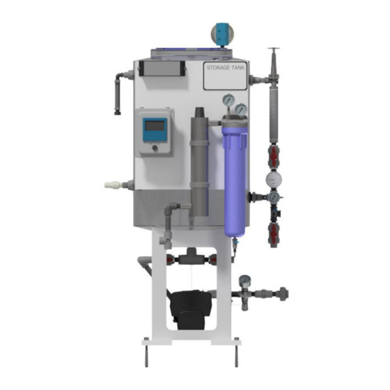
Page 7: Component Identification
COMPONENT IDENTIFICATION LAB STORAGE TANKS COMPONENT IDENTIFICATION 98-0123 Rev E... - Page 8 COMPONENT IDENTIFICATION LAB STORAGE TANKS 98-0123 Rev E...
-
Page 9: Flow Schematic
COMPONENT IDENTIFICATION LAB STORAGE TANKS 2.1 Flow Schematic 98-0123 Rev E... -
Page 10: Installation
INSTALLATION LAB STORAGE TANKS INSTALLATION Locate the storage tank on a firm level floor. For seismic requirements, drill (4) 5/8” diameter holes into the concrete through the mounting holes in the storage tank feet a minimum of 4” deep. Install (4) 5/8” diameter, HILTI KB-TZ Expansion anchors through the 4 holes on the pads to anchor into the ground. -
Page 11: Start-Up
START-UP LAB STORAGE TANKS START-UP 4.1 Pump Start-up The CME pump must be filled with liquid and vented before start-up or if the pump has been drained. To do so: Close the tank-to-pump valve (refer to Section 2 for locations of components). Remove priming plug in the pump sleeve (see Figure 1). -
Page 12: System Start-Up
START-UP LAB STORAGE TANKS Use the ▼ key to scroll down to “Limit-Exceeded Function”. Press the “OK” key to enter the menu. Use the ▼ key to select “Limit” and adjust the limit to approximately one PSI over the operating point of the pump at the new speed using the arrow keys. -
Page 13: Operation
(running dry). All CME pumps provided from AmeriWater have been factory set to control mode “Controlled” (see paragraph below) and have been programmed to operate on a constant curve at the rated flow mentioned previously. -
Page 14: Grundfos® Eye
OPERATION LAB STORAGE TANKS Grundfos® Eye: This shows the operating status of the pump. See Section 5.1.1 for more information. Graphical Colour Display: Displays information and menus Back Button: Returns user to previous menu Left and Right Arrows: With these buttons, the user can navigate between main menus, displays and digits. - Page 15 OPERATION LAB STORAGE TANKS Figure 3 - Grundfos® Eye Indicators 98-0123 Rev E...
-
Page 16: Default Pump Program
OPERATION LAB STORAGE TANKS 5.2 Default Pump Program 98-0123 Rev E... -
Page 17: Disinfection
DISINFECTION LAB STORAGE TANKS DISINFECTION Disconnect the storage tank from the DI process. Remove the 0.2-micron filter (if installed). Prepare DI process for disinfection: a. If using the Silex deionizer, simply remove the packs from the system and set aside. b. -
Page 18: Fault Finding
Do not attempt to carry out any action if it involves inspecting / replacing an electrical / mechanical component without first contacting AmeriWater for advice. Please be aware that the unit / system may still be under pressure and contain water at scalding temperature under certain fault conditions. -
Page 19: Alarms And Events
7.2 Alarms and Events If the pump does not start when the fault has been corrected, or if the fault cannot be corrected, contact AmeriWater or Grundfos for further information. 7.2.1 Grundfos® CME Pump Alarms As mentioned in Section 5.1.1, the alarm indicator light will be shown, as well as the “Status” tab in the “Home”... -
Page 20: Reminder For Adjusting The Set-Point
REMINDER FOR ADJUSTING THE SET-POINT LAB STORAGE TANKS REMINDER FOR ADJUSTING THE SET-POINT An alarm lock occurs when the water quality goes below the low set-point creating an alarm. For the alarm condition to clear, the water quality must rise above the high set-point. When adjusting the set- point, it is suggested to set the high set-point range 1 to 5 mega Ohms above the low set-point to offset the alarm lock. - Page 21 REMINDER FOR ADJUSTING THE SET-POINT LAB STORAGE TANKS The resistivity controller has an on-board single pole, double throw relay that is rated at 1 amp @ 28VDC and 0.5 amp at 120VAC. This has both normally open and normally closed contacts, allowing for control both above and below the set-points.
-
Page 22: Maintenance
MAINTENANCE LAB STORAGE TANKS MAINTENANCE Item Manufacturer Recommendations Vent Filter Replace the vent filter annually or when the filter cartridge gets wet or plugged. It is recommended that a disinfection of the storage tank be performed as Disinfection needed. Replace the post-filter annually or whenever the pressure differential between the Post Filter inlet and the outlet gauges reads 10 PSI or greater. - Page 23 MAINTENANCE LAB STORAGE TANKS Carefully insert the lamp Attach the connector to Ensure that the connector Close the sample port on into the reactor vessel the lamp and note that is fully seated onto the UV the filter housing and turn the connector will only lamp.
-
Page 24: Uv Quartz Sleeve Cleaning / Replacement
MAINTENANCE LAB STORAGE TANKS 9.2 UV Quartz Sleeve Cleaning / Replacement Carefully, remove O-ring Remove the bottom adhering to the quartz Drain the chamber by Remove the top retaining retaining nut, floating sleeve. using the drain port. nut and O-ring. spring, and O-ring. -
Page 25: Uv Sensor Cleaning / Replacement
MAINTENANCE LAB STORAGE TANKS 9.3 UV Sensor Cleaning / Replacement Mineral deposits and sediment may accumulate on the sensor window over time, decreasing the UV energy detected. If the UV controller indicates that the UV intensity is low, one cause may be a stained quartz sleeve and / or sensor window. -
Page 26: Resistivity Meter Calibration
MAINTENANCE LAB STORAGE TANKS 9.4 Resistivity Meter Calibration The resistivity meter should never require calibration. It is recommended to verify the accuracy of the resistivity meter annually by comparing the value shown on the meter against a sample from the post filter sample port and analyzing this with a known good hand meter. -
Page 27: Troubleshooting Guide
TROUBLESHOOTING GUIDE LAB STORAGE TANKS 10 TROUBLESHOOTING GUIDE Symptom Possible Cause Correction High Bacteria UV light quartz sleeve Clean sleeve with scale cleaner Counts dirty Replace quartz sleeve Water Appears Air in water line Run water until air is purged “Milky”... -
Page 28: Replacement Parts
REPLACEMENT PARTS LAB STORAGE TANKS 11 REPLACEMENT PARTS 98-0123 Rev E... -
Page 29: Replacement Instructions
REPLACEMENT INSTRUCTIONS LAB STORAGE TANKS 12 REPLACEMENT INSTRUCTIONS 12.1 Preparation Power down unit and remove the line cord from the power source. Turn off the incoming water to the storage tank. Close the outgoing and return valves on the loop. Relieve the pressure in the system by opening the relief valve on the post filter sample port. - Page 30 REPLACEMENT INSTRUCTIONS LAB STORAGE TANKS Loosen the 4 screws on the rear panel of the access cover to gain access to the terminal strip. Remove 5 wires for the resistivity cell from terminals 7-11 on the terminal strip. Loosen the strain relief on the controller and pull the resistivity cell wires out of the box. Remove the resistivity cell from the tee at the base of the UV light.
- Page 31 REPLACEMENT INSTRUCTIONS LAB STORAGE TANKS Hot wire to terminal 1 Neutral wire to terminal 2 Ground wire to terminal 3. Install resistivity cell wires into the terminal block in the following order: White to terminal 7 ...
- Page 32 To obtain warranty service, notice must be given to the manufacturer within 30 days of the discovery of the defect. There are no warranties on the AmeriWater system beyond those specifically described above. All implied warranties, including any implied warranty of merchantability or of fitness for a particular purpose are disclaimed to the extent they might extend beyond the above periods.
- Page 33 (PVC). The AmeriWater system you have purchased may contain PVC or stainless steel parts. While warnings are only required in the State of California, AmeriWater has initiated the use of Prop 65 labeling for all products to ensure compliance with California regulations. Please note that the above warning does not necessarily mean that the product that you have purchased is unsafe.
Need help?
Do you have a question about the 00HC-4090 and is the answer not in the manual?
Questions and answers