AFRISO TankControl 10 Operating Instructions Manual
Hydrostatic level indicator
Hide thumbs
Also See for TankControl 10:
- Operating instructions manual (44 pages) ,
- Operating instructions manual (197 pages)

Related Manuals for AFRISO TankControl 10


Summary of Contents for AFRISO TankControl 10
- Page 1 Betriebsanleitung Hydrostatisches Füllstandmessgerät TankControl 10 Copyright 2022 AFRISO-EURO-INDEX GmbH. Alle Rechte vorbehalten. Version: 06.2022.0 ID: 900.000.0739...
-
Page 2: Über Diese Betriebsanleitung
Über diese Betriebsanleitung Über diese Betriebsanleitung Diese Betriebsanleitung beschreibt das Hydrostatische Füllstandmessgerät TankControl 10 mit Tauchsonde (im Folgenden auch „Produkt“). Diese Betriebsanleitung ist Teil des Produkts. • Sie dürfen das Produkt erst benutzen, wenn Sie die Betriebsanleitung vollständig gelesen und verstanden haben. -
Page 3: Informationen Zur Sicherheit
Sie alle im Zusammenhang mit diesem Warnsymbol beschriebenen Hinweise, um Unfälle mit Todesfolge, Verlet- zungen und Sachschäden zu vermeiden. Dieses Symbol warnt vor gefährlicher elektrischer Span- nung. Wenn dieses Symbol in einem Warnhinweis gezeigt wird, besteht die Gefahr eines elektrischen Schlags. TankControl 10... - Page 4 Führen Sie bei der Verwendung des Produkts alle Arbeiten ausschließlich unter den in der Betriebsanleitung und auf dem Typenschild spezifizierten Bedingungen und innerhalb der spezifizierten technischen Daten und in Übereinstimmung mit allen am Einsatzort geltenden Bestimmungen, Nor- men und Sicherheitsvorschriften durch. TankControl 10...
- Page 5 Gefährdungen auftreten können, die nicht direkt vom Produkt ausge- hen. Veränderungen am Produkt Führen Sie ausschließlich solche Arbeiten an und mit dem Produkt durch, die in dieser Betriebsanleitung beschrieben sind. Nehmen Sie keine Verände- rungen vor, die in dieser Betriebsanleitung nicht beschrieben sind. TankControl 10...
-
Page 6: Transport Und Lagerung
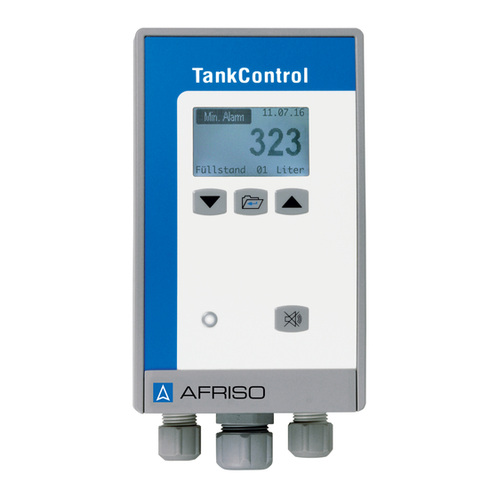
Benutzen Sie für den Transport die Originalverpackung. • Lagern Sie das Produkt nur in trockener, sauberer Umgebung. • Stellen Sie sicher, dass das Produkt bei Transport und Lagerung stoßge- schützt ist. Nichtbeachtung dieser Anweisungen kann zu Sachschäden führen. TankControl 10... - Page 7 Das Auswertegerät enthält in einem schlagfesten Kunststoffgehäuse die Anzeige- und Bedienelemente sowie sämtliche elektronische Komponenten zur Auswertung. A. Display B. Pfeiltaste hoch C. Menütaste D. Quittiertaste - Akustischer Alarm E. Rote LED - Optischer Alarm F. Pfeiltaste runter Abbildung 1: Auswertegerät TankControl 10...
- Page 8 Mit dieser Taste quittieren/schalten Sie den akusti- sche Alarm aus oder gelangen ins Alarmquittiermenü. Optischer Alarm Bei einem Alarm signalisiert die rote LED eine Stö- rung/Alarm. Pfeiltaste hoch Mit dieser Taste nach oben/rechts blättern. Pfeiltaste runter Mit dieser Taste nach unten/links blättern. TankControl 10...
- Page 9 DE DE Produktbeschreibung Abmessungen Abbildung 2: Abmessungen in mm TankControl 10...
- Page 10 Produktbeschreibung Übersicht Tauchsonde A. Sondenkabel mit Entlüftungs- schlauch B. Drucksensor C. Stern D. Abstandhalter Abbildung 3: Tauchsonde Übersicht Schwimmersonde (Optional) A. Zweiadriges Sondenkabel B. Einschraubkörper mit Gewinde G1 C. Messinggewicht D. Schwimmerschalter Abbildung 4: Schwimmersonde TankControl 10...
- Page 11 E. Montageset für Entnahmeflansch an Batterietanks B. Tauchsonde F. Feuchtraum-Abzweigdose mit C. Optional: Schwimmersonde (ZS) Befestigungsmaterial D. Verschraubungsset Zubehör-Beutel (ohne Abbildung) mit G1½ a x G1 i, G2 a x G1½ i Schrauben und Dübeln für Wandbe- festigung TankControl 10...
- Page 12 Produktbeschreibung Anwendungsbeispiel(e) Abbildung 5: Füllstandmessung mit einer Tauchsonde Abbildung 6: Füllstandmessung mit Erfassung der Differenz an Batterietanks TankControl 10...
- Page 13 Die optionale Schwimmersonde (ZS) kann für Rückstaumeldungen (bei- spielsweise bei Regenwassernutzungssystemen) eingesetzt werden. Potentialfreier Wechselkontakt Die potentialfreien Wechselkontakte schalten den Alarm für zusätzliche Geräte (beispielsweise Hupe, Rundumleuchte). Zulassungsdokumente, Bescheinigungen, Erklärungen Das Produkt entspricht: • EMV-Richtlinie (2014/30/EU) • Niederspannungsrichtlinie (2014/35/EU) • RoHS-Richtlinie (2011/65/EU) TankControl 10...
- Page 14 Interne Batterie (integriert) Lithium-Batterie 3,6 V, Typ LS 14500, Li-metal Schutzklasse (EN 60730-1) Schutzart (EN 60529) IP 54 Bemessungsstoßspannung 2500 V Zusätzliche Anschlüsse Relaiskontakte 2 potentialfreie Wechsler Schaltvermögen Relaisausgang Max. 230 V, 2 A Relaissicherung T 2 A TankControl 10...
- Page 15 Bereich 0 ... 70 °C Umgebungsbedingungen Mediumstemperatur -5 ... 70 °C Umgebungstemperatur Lagerung -5 ... 70 °C Elektrische Sicherheit Schutzart (EN 60529) IP 68 *Genauigkeit des Gesamtsystems: ± 1,5 % FSO, IEC 60770, bezogen auf die Anzeige der Füllhöhe in mm. TankControl 10...
- Page 16 Anschlusskabel Ölflex 2 x 0,5 mm² Länge Sondenkabel 5 ... 50 m (geschirmt) Werkstoff Sondenkörper Polypropylen Gehäuse Messing Umgebungsbedingungen Umgebungstemperatur Betrieb -5 ... 50 °C Umgebungstemperatur Lagerung -5 ... 55 °C Elektrische Sicherheit Schutzart (EN 60529) IP 68 TankControl 10...
-
Page 17: Montage
Stellen Sie sicher, dass das Auswertegerät vor direkter Sonneneinstrah- lung geschützt ist. Stellen Sie sicher, dass die Feuchtraum-Abzweigdose wasserdicht ver- schlossen wird. Stellen Sie sicher, dass die Feuchtraum-Abzweigdose nicht luftdicht ver- schlossen wird. TankControl 10... - Page 18 Gehäuse als Bohr- schablone. Variante A 1. Befestigen Sie die Schraube an der Wand. 2. Hängen Sie das Auswer- tegerät ein. 3. Befestigen Sie das Aus- wertegeräte an der Wand mit einer Schraube an der unteren Lasche. TankControl 10...
- Page 19 3. Befestigen Sie die Feuchtraum-Abzweigdose an der Wand. 4. Führen Sie das Kabel des Auswertegerätes in die Feuchtraum-Abzweig- dose. 5. Montieren Sie die Tauchsonde (siehe "Tauchsonde montieren"). 6. Führen Sie das Kabel der Tauchsonde zur Feuchtraum-Abzweigdose. 7. Verbinden Sie die Kabel mittels der Lüsterklemme. TankControl 10...
- Page 20 B. Weiß (U+) C. Grün (Signal) D. Braun (U-) E. Schwarz (Schirm) F. Lüsterklemme G. Kabel von der Tauchsonde Abbildung 7: Anschluss Lüsterklemme 8. Schließen Sie die Feuchtraum-Abzweigdose. 9. Schließen Sie die Versorgungsspannung am Auswertegerät an (siehe "Elektrischer Anschluss"). TankControl 10...
- Page 21 A. Abstandhalter B. Stern C. Drucksensor Abbildung 8: Tauchsonde montieren 1. Stecken Sie den Stern auf den Drucksensor. - Stellen Sie sicher, dass die Rippen am Stern passen. 2. Schrauben Sie den Abstandhalter auf den Stern mit Drucksensor. TankControl 10...
- Page 22 8. Stellen Sie die Kabellänge des Sondenkabels in der Kabelverschraubung so ein, dass die Sondenspitze den Tankboden erreicht. 9. Ziehen Sie den Gewindeadapter so fest, dass sich das Sondenkabel nicht mehr verschieben lässt 10.Ermitteln Sie den tatsächlichen Füllstand (siehe "Füllstand anzeigen"). TankControl 10...
- Page 23 Schwimmersonde befestigt wird, entspricht dem Alarm-Schaltpunkt. 1. Lassen Sie die Schwimmersonde am Kabel hängend in den Tank hinun- ter. 2. Befestigen Sie das Kabel der Schwimmersonde mit dem beiliegenden G1-Einschraubkörper in der Höhe des gewünschten Alarm-Schaltpunk- tes. TankControl 10...
-
Page 24: Elektrostatische Entladung
Stellen Sie sicher, dass durch elektrisch leitfähige Gegenstände oder Medien keine Gefährdungen ausgehen können. Nichtbeachtung dieser Anweisungen führt zu Tod oder schweren Verlet- zungen. HINWEIS ELEKTROSTATISCHE ENTLADUNG • Erden Sie sich immer, bevor Sie die elektronischen Bauteile berühren. Nichtbeachtung dieser Anweisungen kann zu Sachschäden führen. TankControl 10... - Page 25 C. Versorgungsspannung D. Neutralleiter E. Klemme L1 Abbildung 10: Anschlussplan Relais - Normally Open Nicht verbunden mit Klemme A am Anschluss Relais A oder B Relais - Normally Closed Verbunden mit Klemme A am Anschluss Relais A oder B TankControl 10...
- Page 26 1. Führen Sie das Netzkabel durch die rechte Kabelverschraubung in das Auswertegerät. 2. Schließen Sie die Phase an die Klemme L1 (F) an. 3. Schließen Sie den Neutralleiter (E) an. 4. Schließen Sie das Aus- wertegerät. Abbildung 11: Auswertegerät schließen 5. Schalten Sie die bauseitige Spannungsversorgung an. TankControl 10...
- Page 27 1. Führen Sie das Sondenkabel durch die mittlere Kabelverschraubung in das Auswertegerät. 2. Schließen Sie das Sondenkabel an „Sensor2“ wie folgt an: - Klemme „Signal“ - Klemme „AGND“ 3. Schalten Sie die Sonde in der Software des Auswertegerätes frei (siehe "Passwort einstellen"). TankControl 10...
- Page 28 - Max. Alarm - Sensor? - Min. Alarm - Diff. Alarm - Schw. Alarm B. Datum - TT/MM/Jahr C. Messwert D. Einheit E. Sondennummer: - 01 - 02 F. Messgröße: - Füllhöhe - Füllstand G. Wechselkontakt H. Alarm TankControl 10...
- Page 29 DE DE Inbetriebnahme Sprache einstellen TankControl 10...
- Page 30 Inbetriebnahme Passwort einstellen • Passwort für zusätzliche Tauchsonde (ZT): 726452 • Passwort für Schwimmersonden (ZS): 234585 TankControl 10...
- Page 31 DE DE Inbetriebnahme Datum und Uhrzeit einstellen TankControl 10...
- Page 32 Wenn Sie eine Schwimmersonde verwenden, brauchen Sie keine Tankdaten einstellen. 6.5.1 Tankform auswählen Sie können zwischen folgenden Tankformen wählen: • Kunststoff-Batterietank • Linearer Tank • Röhrenförmiger Tank • Kugelförmiger Tank • Zylindrisch liegender Tank • Kunststofftank mit Ausnehmung • Halbkugelförmiger Tank TankControl 10...
- Page 33 DE DE Inbetriebnahme 6.5.2 Tankvolumen, Tankhöhe und Füllhöhe einstellen TankControl 10...
- Page 34 Stellen Sie sicher, dass die Netzspannung angeschlossen und ange- schaltet ist. 1. Stellen Sie den Wert „Aktuelle Füllhöhe“ auf den Wert „000000 mm²“ (siehe "Tankvolumen, Tankhöhe und Füllhöhe einstellen"). 2. Der Nullpunkt der Tauchsonde ist gespeichert. TankControl 10...
- Page 35 DE DE Inbetriebnahme Alarm einstellen 6.7.1 Summer und Wechselkontakt für Tauchsonde 1 einstellen TankControl 10...
- Page 36 Inbetriebnahme 6.7.2 Summer und Wechselkontakt für Tauchsonde 2 einstellen 1. Rufen Sie das Menü „Alarme 02“ auf. 2. Gehen Sie weiter vor, wie im Kapitel "Summer und Wechselkontakt für Tauchsonde 1 einstellen" beschrieben. TankControl 10...
- Page 37 DE DE Inbetriebnahme 6.7.3 Summer und Wechselkontakt für Schwimmersonde einstellen TankControl 10...
- Page 38 Inbetriebnahme 6.7.4 Alarm-Schaltpunkt für Schwimmersonde einstellen TankControl 10...
- Page 39 DE DE Inbetriebnahme 6.7.5 Alarm-Schaltpunkt für Tauchsonde 1 einstellen TankControl 10...
- Page 40 Die Prozentangabe der Alarmgrenze bezieht sich auf die tolerierte Diffe- renz der beiden Füllhöhen. - Bei Überschreitung der Differenz wird Alarm ausgelöst 1. Rufen Sie das Menü „Alarme 02“ auf 2. Gehen Sie weiter vor, wie im Kapitel "Alarm-Schaltpunkt für Schwim- mersonde einstellen" beschrieben. TankControl 10...
-
Page 41: Betrieb
DE DE Betrieb Betrieb Die Beleuchtung des Displays erlischt 5 Minuten nach dem letzten Tasten- druck. Füllstand anzeigen 7.1.1 Mit einer Tauchsonde 7.1.2 Mit zwei Tauchsonden 7.1.3 Mit Schwimmersonde TankControl 10... - Page 42 (wenn eingestellt) 1. Drücken Sie die Quittiertaste, um den akustischen Alarm auszuschalten. - Das Alarmquittiermenü öffnet sich. 2. Relais quittieren Relais ist nicht angezogen und muss nicht quittiert werden. Relais ist angezogen und kann quittiert werden. Relais ist quittiert. TankControl 10...
- Page 43 DE DE Betrieb Statistiken Mit der Statistikfunktion kann der Verbrauch und der Füllstand als Historie oder als Prognose angezeigt werden. - Die Statistik wird immer am Monatsanfang aufgefrischt. TankControl 10...
- Page 44 Verbrauch für den kommenden Zeitraum (bis maximal 12 Monate) in Liter an. - Die Prognosefunktion ist erst ein Jahr nach Inbetriebnahme verfügbar. - Bei Abfrage der Prognose im ersten Jahr wird angezeigt, ab wann die Prognosefunktion verfügbar ist: „Verfügbar ab TT.MM.JJ“. TankControl 10...
-
Page 45: Wartung
Beseitigen Sie die Alarmursache Leitungsunterbre- Prüfen Sie das Son- chung des Sondenka- denkabel bels Falsche Füllstandan- Tankdaten falsch ein- Geben Sie die Tankda- zeige gegeben ten neu ein Sonstige Störungen Bitte wenden Sie sich an die AFRISO-Service Hotline TankControl 10... -
Page 46: Außerbetriebnahme Und Entsorgung
Nichtbeachtung dieser Anweisungen führt zu Tod oder schweren Verlet- zungen. • Setzen Sie Batterien keinen mechanischen Belastungen aus. • Werfen Sie Batterien niemals ins Feuer. • Halten Sie die angegebenen Umgebungsbedingungen (siehe "Techni- sche Daten") ein. • Verwenden Sie keine beschädigten, verformten oder heißen Batterien. TankControl 10... -
Page 47: Gewährleistung
Vor einer Rücksendung Ihres Produkts müssen Sie sich mit uns in Verbin- dung setzen (service@afriso.de). Gewährleistung Informationen zur Gewährleistung finden Sie in unseren Allgemeinen Geschäftsbedingungen im Internet unter www.afriso.com oder in Ihrem Kauf- vertrag. Ersatzteile und Zubehör HINWEIS UNGEEIGNETE TEILE •... -
Page 48: Ersatzteile Und Zubehör
Ersatzteile und Zubehör Ersatzteile und Zubehör Artikelbezeichnung Art.-Nr. Abbildung Zusätzliche Tauchsonde (ZT) 52152 Schwimmersonde (ZS) 16703 Abzweigdose 31824 Kabelverschraubungsset 52125 Zusatzalarmgerät ZAG 01 40633 Rundumleuchte 61015 Hupe KH 1 61011 Warnlichthupe 61020 Hupe HPW 2 61012 TankControl 10... - Page 49 DE DE Anhang Anhang 14.1 EU-Konformitätserklärung TankControl 10...
- Page 50 Operating instructions Hydrostatic level indicator TankControl 10 Copyright 2022 AFRISO-EURO-INDEX GmbH. All rights reserved. Version: 06.2022.0 ID: 900.000.0739...
- Page 51 The manufacturer shall not be liable in any form whatsoever for direct or con- sequential damage resulting from failure to observe these operating instruc- tions or from failure to comply with directives, regulations and standards and any other statutory requirements applicable at the installation site of the prod- uct. TankControl 10...
-
Page 52: Information On Safety
This symbol alerts to hazardous electrical voltage. If this symbol is used in a safety message, there is a hazard of electric shock. TankControl 10... - Page 53 TankControl 10...
- Page 54 Modifications to the product Only perform work on and with the product which is explicitly described in these operating instructions. Do not make any modifications to the product which are not described in these operating instructions. TankControl 10...
-
Page 55: Transport And Storage
Use the original packaging when transporting the product. • Store the product in a clean and dry environment. • Verify that the product is protected against shocks and impact during trans- port and storage. Failure to follow these instructions can result in equipment damage. TankControl 10... -
Page 56: Product Description
A. Display B. Arrow up key C. Menu key D. Acknowledge key - Audible alarm off E. Red LED - Visual alarm F. Arrow down key Fig. 1: Control unit TankControl 10... - Page 57 Visual alarm In the case of an alarm, the red LED indicates an error/alarm. Arrow up key Scroll to the top/right with this key. Arrow down key Scroll to the bottom/left with this key. TankControl 10...
- Page 58 EN E N Product description Dimensions Fig. 2: Dimensions in mm TankControl 10...
- Page 59 A. Probe cable with vent hose B. Pressure sensor C. Star D. Spacer Fig. 3: Submersible probe Overview floating probe (optional) A. Two-wire probe cable B. Screw fitting with thread G1 C. Brass weight D. Float switch Fig. 4: Floating probe TankControl 10...
- Page 60 F. Moisture-proof junction box with C. Optional: Floating probe (ZS) mounting accessories D. Screw connector kit Bag of accessories (not shown) with G1½ a x G1 i, G2 a x G1½ i screws and dowels for wall mounting TankControl 10...
- Page 61 Product description Application example(s) Fig. 5: Level measurement with one submersible probe Fig. 6: Level measurement with detection of difference at battery tanks TankControl 10...
- Page 62 The voltage-free changeover contacts switch the alarm for additional equip- ment (for example, horn, warning light with rotating reflector). Approvals, conformities, certifications The product complies with: • EMC Directive (2014/30/EU) • Low Voltage Directive (2014/35/EU) • RoHS Directive (2011/65/EU) TankControl 10...
- Page 63 Protection class (EN 60730-1) Degree of protection (EN 60529) IP 54 Rated impulse voltage 2500 V Additional connections Relay contacts 2 voltage-free changeover contacts Breaking capacity relay output Max. 230 V, 2 A Relay fuse T 2 A TankControl 10...
- Page 64 -5 ... 70 °C Ambient temperature storage -5 ... 70 °C Electrical safety Degree of protection (EN 60529) IP 68 *Accuracy of the complete system with reference to the indication of the liquid level in mm: ±1.5 % FSO, IEC 60770. TankControl 10...
- Page 65 Length of probe cable 5 ... 50 m (shielded) Material probe body Polypropylene Housing Brass Ambient conditions Ambient temperature operation -5 ... 50 °C Ambient temperature storage -5 ... 55 °C Electrical safety Degree of protection (EN 60529) IP 68 TankControl 10...
- Page 66 Verify that the control unit is protected from direct sunlight. Verify that the the moisture-proof junction box is closed in such a way that it is water-tight. Verify that the moisture-proof junction box is closed in such a way that it is not air-tight. TankControl 10...
- Page 67 A or B. Use the housing as a drilling template. Mounting type A 1. Mount the screw to the wall. 2. Fit the control unit. 3. Fasten the control unit by screwing the bottom lug to the wall. TankControl 10...
- Page 68 4. Route the cable of the the control unit into the moisture-proof junction box. 5. Mount the submersible probe "Mounting the submersible probe". 6. Route the cable of the submersible probe to the moisture-proof junction box. 7. Connect the cables using the terminal strip. TankControl 10...
- Page 69 D. Brown (U-) E. Black (shield) F. Terminal strip G. Cable from submersible probe Fig. 7: Connection terminal strip 8. Close the moisture-proof junction box. 9. Connect the supply voltage to the control unit (see "Electrical connec- tion"). TankControl 10...
- Page 70 B. Star C. Pressure sensor Fig. 8: Mounting the submersible probe 1. Plug the star onto the pressure sensor. - Verify that the ribs at the star fit. 2. Screw the spacer with the star onto the pressure sensor. TankControl 10...
- Page 71 8. At the cable gland, adjust the cable length of the probe cable in such a way that the probe tip reaches the tank bottom. 9. Tighten the threaded adapter so that the probe cable can no longer be moved 10.Determine the actual level "Displaying the level". TankControl 10...
- Page 72 1. Suspend the floating probe into the tank at the cable. 2. Fasten the cable of the floating probe with the enclosed G1 screw fitting at the height/level of the required alarm switching point. TankControl 10...
-
Page 73: Electric Shock
Verify that no hazards can be caused by electrically conductive objects or media. Failure to follow these instructions will result in death or serious injury. NOTICE ELECTROSTATIC DISCHARGE • Always earth yourself before touching electronic components. Failure to follow these instructions can result in equipment damage. TankControl 10... - Page 74 D. Neutral conductor E. Terminal L1 Fig. 10: Wiring diagram Relay - Normally Open Not connected to terminal A at connec- tion relay A or B Relay - Normally Closed Connected to terminal A at connection relay A or B TankControl 10...
- Page 75 1. Route the mains cable through the right cable gland into the control unit. 2. Connect the phase to terminal L1 (F). 3. Connect the neutral conductor (E). 4. Close the control unit. Fig. 11: Connecting the control unit 5. Switch on the on-site power supply. TankControl 10...
- Page 76 1. Route the probe cable through the centre cable gland into the control unit. 2. Connect the probe cable to "Sensor2" as follows: - Terminal "Signal" - Terminal "AGND" 3. Enable the software for the additional probe at the control unit see "Set- ting the password". TankControl 10...
- Page 77 - Min. alarm - Diff. Alarm - Schw. alarm B. Date - DD/MM/year C. Measured value D. Unit E. Number of probe: - 01 - 02 F. Measured variable: - Liquid level - Level G. Changeover contact H. Alarm TankControl 10...
- Page 78 EN E N Commissioning Adjusting the language TankControl 10...
- Page 79 Commissioning Setting the password • Password for additional submersible probe (ZT): 726452 • Password for floating probes (ZS): 234585 TankControl 10...
- Page 80 EN E N Commissioning Setting date and time TankControl 10...
- Page 81 6.5.1 Selecting the tank shape You can select one of the following tank shapes: • Plastic battery tank • Linear tank • Cylindrical tank • Spherical tank • Oval tank • Plastic tank with recess • Hemispherical tank TankControl 10...
- Page 82 EN E N Commissioning 6.5.2 Setting the tank volume, tank height and liquid level TankControl 10...
- Page 83 Verify that mains voltage is connected and switched on. 1. Set the value "Aktuelle Füllhöhe" to the value "000000 mm²“ see "Setting the tank volume, tank height and liquid level". 2. The zero point of the submersible probe has been saved. TankControl 10...
- Page 84 EN E N Commissioning Adjusting the alarm 6.7.1 Setting the buzzer and changeover contact for submersible probe 1 TankControl 10...
- Page 85 Commissioning 6.7.2 Setting the buzzer and changeover contact for submersible probe 2 1. Display the menu "Alarme 02". 2. Proceed as described in chapter "Setting the buzzer and changeover contact for submersible probe 1". TankControl 10...
- Page 86 EN E N Commissioning 6.7.3 Setting the buzzer and the changeover contact for the floating probe TankControl 10...
- Page 87 Commissioning 6.7.4 Setting the alarm switching point for the floating probe TankControl 10...
- Page 88 EN E N Commissioning 6.7.5 Setting the alarm switching point for submersible probe 1 TankControl 10...
- Page 89 The percentage relates to the tolerated difference between the two liquid levels. - If the difference is exceeded, an alarm is triggered 1. Display the menu "Alarme 02" 2. Proceed as described in chapter “Setting the alarm switching point for the floating probe” on page 38. TankControl 10...
-
Page 90: Operation
EN E N Operation Operation The display backlight is switched off 5 minutes after the last time a key was pressed. Displaying the level 7.1.1 With one submersible probe 7.1.2 With two submersible probes 7.1.3 With floating probe TankControl 10... - Page 91 1. Press the Acknowledge key to switch off the audible alarm. - The alarm acknowledgement menu is displayed. 2. Acknowledging the relay Relay is not energised and does not need to be acknowl- edged. Relay is energised and can be acknowledged. Relay has been acknowledged. TankControl 10...
- Page 92 EN E N Operation Statistics With the statistics function, the consumption and the level can be displayed as a history or as a forecast. - The statistics is refreshed every first day of the month. TankControl 10...
- Page 93 - The forecast function is not available until one year after commission- ing. - If the forecast function is activated during the first year, the system dis- plays the date as of which the forecast will be available (DD.MM.YY). TankControl 10...
-
Page 94: Maintenance
Alarm condition Remove the cause of the alarm Line interruption in the Check the probe cable probe cable Incorrect level indica- Incorrect tank data Enter the tank data tion entered again Other malfunctions Contact the AFRISO service hotline TankControl 10... -
Page 95: Decommissioning / Disposal
Failure to follow these instructions will result in death or serious injury. • Do not subject batteries to mechanical stress. • Never throw batteries into fire. • Comply with the specified ambient conditions ("Technical specifications"). • Do not use damaged, deformed or hot batteries. TankControl 10... -
Page 96: Returning The Device
EN E N Returning the device Returning the device Get in touch with us before returning your product (service@afriso.de). Warranty See our terms and conditions at www.afriso.com or your purchase contract for information on warranty. Spare parts and accessories NOTICE UNSUITABLE PARTS •... -
Page 97: Spare Parts And Accessories
52152 Floating probe (ZS) 16703 Junction box 31824 Cable gland kit 52125 Additional alarm unit ZAG 01 40633 Warning light with rotating reflector 61015 Horn KH 1 61011 Combined alarm light and horn 61020 Horn HPW 2 61012 TankControl 10... - Page 98 EN E N Appendix Appendix 14.1 EU Declaration of Conformity TankControl 10...
- Page 99 Notice technique Indicateur de niveau hydrostatique TankControl 10 Copyright 2022 AFRISO-EURO-INDEX GmbH. Tous droits réservés. Version: 06.2022.0 ID: 900.000.0739...
- Page 100 La présente notice technique La présente notice technique Cette notice technique contient la description d'indicateur de niveau hydros- tatique TankControl 10 avec sonde à immersion (dénommé ci-après "pro- duit"). Cette notice technique fait partie du produit. • Utilisez le produit seulement après que vous aurez lu et compris intégra- lement la notice technique.
-
Page 101: Informations Sur La Sécurité
Ce pictogramme avertit d'une tension électrique dange- reuse. Si ce pictogramme s'affiche dans une consigne de sécurité, il y a un risque de choc électrique. TankControl 10... - Page 102 Pendant l'utilisation du produit effectuez toutes les opérations exclusivement dans les conditions spécifiées dans cette notice technique et sur la plaque signalétique, conformément aux données techniques spécifiées et en accord avec tous les règlements, normes et consignes de sécurité en vigueur sur le lieu d'installation. TankControl 10...
- Page 103 Modification du produit En travaillant sur le produit et avec celui-ci, effectuez exclusivement les opé- rations décrites dans cette notice technique. N'effectuez pas de modifica- tions non décrites dans cette notice technique. TankControl 10...
-
Page 104: Transport Et Stockage
Utilisez l'emballage d'origine pour le transport. • Stockez le produit dans un lieu sec et propre. • Assurez-vous que le produit est à l'abri des chocs pendant le transport et le stockage. La non-observation de ces instructions peut causer des dommages maté- riels. TankControl 10... -
Page 105: Description Du Produit
A. Affichage B. Touche flèche vers le haut C. Touche Menu D. Touche d'acquitte- ment - Alarme sonore désactivée E. LED rouge - Affichage d’état alarme F. Touche flèche vers le Figure 1: Unité de commande TankControl 10... - Page 106 En cas d'alarme, la LED rouge signale un défaut/une alarme. Touche flèche vers le haut Cette touche vous permet de faire défiler vers le haut/la droite. Touche flèche vers le bas Cette touche vous permet de faire défiler vers le bas/la gauche. TankControl 10...
- Page 107 FR F R Description du produit Dimensions Figure 2: Dimensions en mm TankControl 10...
- Page 108 Figure 3: Sonde à immersion Aperçu sonde à flotteur (en option) A. Câble de sonde à deux fils B. Raccord à visser avec filetage G1 C. Poids en laiton D. Interrupteur à flotteur Figure 4: Sonde à flotteur TankControl 10...
- Page 109 C. En option : Sonde à flotteur (ZS) matériau de fixation D. Set de raccords à vis Sachet d'accessoires (non représen- G1½ male x G1 femelle, tés) avec vis et chevilles pour fixation G2 a x G1½ male au mur TankControl 10...
- Page 110 Description du produit Exemple(s) d'application Figure 5: Mesure de niveau de remplissage avec une sonde à immersion Figure 6: Mesure de niveau de remplissage avec détection de la différence de réser- voirs en batterie TankControl 10...
- Page 111 Les contacts inverseurs libre de potentiel permet l'activation de l'alarme sur les équipements supplémentaires (par exemple, avertisseur sonore, gyro- phare). Agréments, certificats, déclarations Le produit est conforme à : • Directive CEM (2014/30/UE) • Directive basse tension (2014/35/UE) • Directive RoHS (2011/65/UE) TankControl 10...
- Page 112 Degré de protection (EN 60529) IP 54 Tension assignée de tenue aux chocs 2500 V Branchements supplémentaires Contacts relais 2 contacts inverseur libre de poten- tiel Pouvoir de coupure sortie de relais 230 V max., 2 A Fusible relais T 2 A TankControl 10...
- Page 113 Température ambiante stockage -5 ... 70 °C Sécurité électrique Degré de protection (EN 60529) IP 68 *Précision du système complet relative à la hauteur du niveau de remplissage en mm : ±1,5 % sortie plein échelle FSO, IEC 60770. TankControl 10...
- Page 114 Longueur câble de sonde 5 ... 50 m (blindé) Matériau corps de sonde Polypropylène Boîtier Laiton Conditions ambiantes Température ambiante service -5 ... 50 °C Température ambiante stockage -5 ... 55 °C Sécurité électrique Degré de protection (EN 60529) IP 68 TankControl 10...
-
Page 115: Montage
Assurez-vous que l'unité de commande est protégée contre la lumière directe du soleil. Assurez-vous que la boîte de jonction étanche est fermée de sorte qu'elle soit étanche à l'eau. Assurez-vous que la boîte de jonction étanche n'est pas hermétiquement fermée. TankControl 10... - Page 116 Type de fixation A 1. Introduisez la vis dans le mur. 2. Accrochez l'unité de com- mande. 3. Fixez l'unité de com- mande sur la paroi en vis- sant la vis dans la patte inférieure. TankControl 10...
- Page 117 4. Faites passer le câble de l'unité de commande dans la boîte de jonction étanche. 5. Montez la sonde à immersion. "Montage de la sonde à immersion". 6. Faites passer le câble de la sonde à immersion vers la boîte de jonction étanche. 7. Raccordez les câbles avec le serre-fils. TankControl 10...
- Page 118 C. Vert (signal) D. Brun (U-) E. Noir (blindage) F. Serre-fils G. Câble de la sonde à immersion Figure 7: Raccordement serre-fils 8. Fermez la boîte de jonction étanche. 9. Branchez l'unité de commande à l'alimentation (voir "Branchement élec- trique"). TankControl 10...
- Page 119 C. Capteur de pression Figure 8: Montage de la sonde à immersion 1. Installez le croisillon sur le capteur de pression. - Respectez la position des nervures du croisillon. 2. Serrez l'espaceur sur le croisillon avec le capteur de pression. TankControl 10...
- Page 120 9. Serrez l'adaptateur fileté de sorte que le câble de la sonde ne se déplace plus 10.Déterminez le niveau de remplissage actuel "Afficher le niveau de rem- plissage". TankControl 10...
- Page 121 1. Laissez la sonde flottante sur le câble dans le réservoir. 2. Fixez le câble de la sonde à flotteur avec le raccord à visser G1 fourni au point de commutation d'alarme souhaité. TankControl 10...
-
Page 122: Choc Électrique
La non-observation de ces instructions entraîne la mort ou des blessures graves. AVIS DÉCHARGES ÉLECTROSTATIQUES • Reliez-vous à la terre avant de toucher des composants susceptibles d'être endommagés par décharge électrostatique. La non-observation de ces instructions peut causer des dommages maté- riels. TankControl 10... - Page 123 E. Borne L1 Figure 10: Schéma de câblage Relais - Normally Open Pas de liaison vers borne A de la connexion A ou B Relais - Normally Closed Liaison vers borne A de la connexion A ou B TankControl 10...
- Page 124 1. Faites passer le câble secteur par le presse-étoupe à droit dans l'unité de commande. 2. Branchez la phase à la borne L1 (F). 3. Branchez le neutre (E). 4. Fermez l'unité de com- mande. Figure 11: Branchement unité de commande 5. Activez l'alimentation sur place. TankControl 10...
- Page 125 2. Branchez le câble de la sonde sur "Sensor2" de la manière suivante : - Borne "Signal" - Borne "AGND" 3. Activez le logiciel pour la sonde supplémentaire sur l'unité de com- mande voir "Régler le mot de passe". TankControl 10...
-
Page 126: Mise En Service
- Diff. Alarme - Schw. Alarm B. Date - TT/MM/année C. Valeur mesurée D. Unité E. Numéro de la sonde : - 01 - 02 F. Mesure : - Niveau de remplissage - Niveau G. Contact inverseur H. Alarme TankControl 10... - Page 127 FR F R Mise en service Régler la langue TankControl 10...
- Page 128 Mise en service Régler le mot de passe • Mode de passe pour sonde à immersion supplémentaire (ZT) : 726452 • Mode de passe pour sondes à flotteur (ZS): 234585 TankControl 10...
- Page 129 FR F R Mise en service Régler la date et l'heure TankControl 10...
- Page 130 Sélectionner la forme du réservoir Vous pouvez sélectionner les formes de réservoir suivantes : • Réservoir plastique monté en batterie • Réservoir linéaire • Réservoir cylindrique • Réservoir sphérique • Réservoir ovale • Réservoir plastique avec échancrure • Réservoir hémisphérique TankControl 10...
- Page 131 FR F R Mise en service 6.5.2 Régler le volume du réservoir, l'hauteur de réservoir et le niveau TankControl 10...
- Page 132 Assurez-vous que la tension secteur est connectée et activée. 1. Réglez la valeur "Aktuelle Füllhöhe" sur la valeur "000000 mm²" voir "Régler le volume du réservoir, l'hauteur de réservoir et le niveau". 2. Le point zéro de la sonde à immersion a été enregistré. TankControl 10...
- Page 133 FR F R Mise en service Régler l'alarme 6.7.1 Régler le buzzer et le contact inverseur pour la sonde à immer- sion 1 TankControl 10...
- Page 134 Régler le buzzer et le contact inverseur pour la sonde à immer- sion 2 1. Affichez le menu "Alarme 02". 2. Procédez comme décrit dans le chapitre "Régler le buzzer et le contact inverseur pour la sonde à immersion 1". TankControl 10...
- Page 135 FR F R Mise en service 6.7.3 Régler le buzzer et le contact inverseur pour la sonde à flotteur TankControl 10...
- Page 136 Mise en service 6.7.4 Régler le point d'alarme pour la sonde à flotteur TankControl 10...
- Page 137 FR F R Mise en service 6.7.5 Régler le point d'alarme pour la sonde à immersion 1 TankControl 10...
- Page 138 Le pourcentage pour le seuil d'alarme se rapporte à la différence tolérée entre les deux niveaux. - L'alarme est déclenchée si la différence est dépassée 1. Affichez le menu "Alarme 02" 2. Procédez comme décrit dans le chapitre "Régler le point d'alarme pour la sonde à flotteur", page 38. TankControl 10...
- Page 139 Service Service L'éclairage de l'affichage s'éteint automatiquement 5 minutes après la der- nière actionnement d'une touche. Afficher le niveau de remplissage 7.1.1 Avec une sonde à immersion 7.1.2 Avec deux sondes à immersion 7.1.3 Avec sonde à flotteur TankControl 10...
- Page 140 1. Appuyez sur la touche Touche d'acquittement pour arrêter l'alarme sonore. - Le menu d'acquittement d'alarme s'affiche. 2. Acquittement du relais Le relais n'est pas activé et ne doit pas être acquitté. Le relais est activé et peut être acquitté. Le relais est acquitté. TankControl 10...
- Page 141 FR F R Service Statistiques Avec la fonction statistique, la consommation et le niveau de remplissage peuvent être affichés sous forme d'historique ou de prévision. - La statistique est mise à jour au début de chaque mois. TankControl 10...
- Page 142 - La fonction de prévision n'est disponible qu'un an après la mise en ser- vice. - En cas de consultation de la fonction de prévision au cours de la pre- mière année, il y a affichage de : "disponible à partir de JJ.MM.AA". TankControl 10...
-
Page 143: Suppression Des Dérangements
Eliminez la cause d'alarme Câble de sonde inter- Vérifiez le câble de rompu sonde Erreur d'affichage du Erreur d'entrée des Entrez les données du niveau données du réservoir réservoir correctes Autre dérangement Veuillez contacter l'AFRISO Service Hot- line TankControl 10... -
Page 144: Mise Hors Service Et Élimination
La non-observation de ces instructions entraîne la mort ou des blessures graves. • Ne soumettez pas les piles à des contraintes mécaniques. • Ne jetez jamais les piles au feu. • Respectez les conditions ambiantes spécifiées ("Caractéristiques tech- niques"). • N'utilisez pas de piles endommagées, déformées ou chaudes. TankControl 10... -
Page 145: Garantie
Avant de retourner le produit, il faut que vous preniez contact avec nous (ser- vice@afriso.de). Garantie Les informations sur la garantie figurent dans nos "Conditions générales de vente" sur le site www.afriso.com ou dans votre contrat d'achat. Pièces détachées et accessoires AVIS PIÈCES INADAPTÉES •... -
Page 146: Pièces Détachées Et Accessoires
Sonde à immersion supplémentaire (ZT) 52152 Sonde à flotteur (ZS) 16703 Boîte de jonction 31824 Kit de presse-étoupe 52125 Unité d'alarme supplémentaire ZAG 01 40633 Gyrophare 61015 Avertisseur sonore KH 1 61011 Gyrophare avec avertisseur sonore 61020 Avertisseur sonore HPW 2 61012 TankControl 10... - Page 147 FR F R Annexe Annexe 14.1 Déclaration de conformité UE TankControl 10...
Need help?
Do you have a question about the TankControl 10 and is the answer not in the manual?
Questions and answers