Table of Contents
Advertisement
Available languages
Available languages
Quick Links
Betriebsanleitung
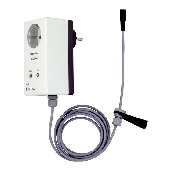
Heizölmelder Steckergehäuse
HMS
Typ: HMS mit Sonde 2,00 m
Copyright 2015 AFRISO-EURO-INDEX GmbH. Alle Rechte vorbehalten.
Lindenstraße 20
74363 Güglingen
Telefon +49 7135-102-0
Heizölmelder
Z-65.40-214
Service +49 7135-102-211
Telefax +49 7135-102-147
info@afriso.com
Version: 10.2015.0
www.afriso.com
ID: 900.000.0269
Advertisement
Table of Contents

Subscribe to Our Youtube Channel
Related Manuals for AFRISO HMS


Summary of Contents for AFRISO HMS
- Page 1 Betriebsanleitung Heizölmelder Steckergehäuse Typ: HMS mit Sonde 2,00 m Copyright 2015 AFRISO-EURO-INDEX GmbH. Alle Rechte vorbehalten. Lindenstraße 20 74363 Güglingen Telefon +49 7135-102-0 Heizölmelder Z-65.40-214 Service +49 7135-102-211 Telefax +49 7135-102-147 info@afriso.com Version: 10.2015.0 www.afriso.com ID: 900.000.0269...
-
Page 2: Über Diese Betriebsanleitung
Über diese Betriebsanleitung Über diese Betriebsanleitung Diese Betriebsanleitung beschreibt den Heizölmelder „HMS“ (im folgenden auch „Produkt“). Diese Betriebsanleitung ist Teil des Produkts. • Sie dürfen das Produkt erst benutzen, wenn Sie die Betriebsanleitung vollständig gelesen und verstanden haben. • Stellen Sie sicher, dass die Betriebsanleitung für alle Arbeiten an und mit dem Produkt jederzeit verfügbar ist. -
Page 3: Informationen Zur Sicherheit
Informationen zur Sicherheit Informationen zur Sicherheit Warnhinweise und Gefahrenklassen In dieser Betriebsanleitung finden Sie Warnhinweise, die auf potenzielle Gefahren und Risiken aufmerksam machen. Zusätzlich zu den Anweisungen in dieser Betriebsanleitung müssen Sie alle am Einsatzort des Produktes geltenden Bestimmungen, Normen und Sicherheitsvorschriften beachten. Stellen Sie vor Verwendung des Produktes sicher, dass Ihnen alle Bestim- mungen, Normen und Sicherheitsvorschriften bekannt sind und dass sie befolgt werden. - Page 4 Informationen zur Sicherheit Bestimmungsgemäße Verwendung Dieses Produkt eignet sich ausschließlich zur Meldung von Ölansammlun- gen bei der Überwachung von: • Auffangwannen unter Lagerbehältern, Brennern oder Motoren • Behältern (Tanks) mit nicht einsehbaren Auffangräumen • Auffangräumen unter ölverbrauchenden Produkten • Domschächten, Rohr- oder Kabelkanälen •...
- Page 5 Informationen zur Sicherheit Führen Sie bei der Verwendung des Produkts alle Arbeiten ausschließlich unter den in der Betriebsanleitung und auf dem Typenschild spezifizierten Bedingungen und innerhalb der spezifizierten technischen Daten und in Übereinstimmung mit allen am Einsatzort geltenden Bestimmungen, Nor- men und Sicherheitsvorschriften durch.
-
Page 6: Transport Und Lagerung
Transport und Lagerung Transport und Lagerung Das Produkt kann durch unsachgemäßen Transport und Lagerung beschä- digt werden. HINWEIS BESCHÄDIGUNG DES PRODUKTS • Stellen Sie sicher, dass während des Transports und der Lagerung des Pro- dukts die spezifizierten Umgebungsbedingungen eingehalten werden. •... - Page 7 Produktbeschreibung Produktbeschreibung Funktion Das Produkt besteht aus dem Signalteil und einer opto-elektronischen Sonde. Wenn kein Leck vorliegt, leuchtet die grüne LED. Wenn die Sonde in Flüssig- keit eintaucht, alarmiert das Signalteil optisch mit einer roten LED und die Steckdose im Signalteil wird abgeschaltet. Sonde Die optoelektronische Sonde erfasst das unterschiedliche optische Verhalten von Luft und Flüssigkeiten.
- Page 8 Produktbeschreibung Technische Daten 4.3.1 Signalteil Parameter Wert Allgemeine Daten Abmessungen (B x H x T) 65 x 120 x 92 mm Aufbau Steckergehäuse Gewicht 0,35 kg Ansprechverzögerung Keine Ausgangssignal 1 Ausgangsrelais (Wechsler) Schaltvermögen Ausgangsrelais AC 230 V 1800 VA, DC 100 V 300 W Temperatureinsatzbereich Umgebung -10/+60 °C...
- Page 9 Produktbeschreibung 4.3.2 Sonde Parameter Wert Allgemeine Daten Abmessungen Sondenkopf (Ø x L) 10 x 33 mm Material Sondenkopf Polyamid-Schmelzklebstoff Funktionsteile Infrarot-Sender/-Empfänger Anschlusskabel: LiYY 3 x 0,25 mm² Standardlänge Max. Länge 50 m (geschirmt) Gewicht 0,05 kg Temperatureinsatzbereich Umgebung -10/+60 °C Lagerung -10/+60 °C...
-
Page 10: Montage
Montage Montage Sonde montieren 1. Befestigen Sie die Sonde am tiefsten Punkt des zu überwachenden Rau- mes hängend oder liegend. - Montieren Sie die Sondenspitze so, dass sie bei geringen Ölmengen in die Flüssigkeit eintaucht und somit frühzeitig einen Alarm auslöst. 2. - Page 11 Montage Halterung montieren 1. Montieren Sie die Halterung (waagrecht oder senkrecht) mit einer Schraube. Signalteil montieren Stellen Sie sicher, dass am Montageort die zulässige Umgebungstempe- ratur nicht überschritten wird. Stellen Sie sicher, dass das Signalteil jederzeit zugänglich und einsehbar ist.
- Page 12 Montage Elektrischer Anschluss GEFAHR ELEKTRISCHER SCHLAG • Stellen Sie sicher, dass durch die Art der elektrischen Installation der Schutz gegen elektrischen Schlag (Schutzklasse, Schutzisolierung) nicht vermin- dert wird. Nichtbeachtung dieser Anweisungen führt zu Tod oder schweren Verlet- zungen. GEFAHR ELEKTRISCHER SCHLAG DURCH SPANNUNGSFÜHRENDE TEILE •...
- Page 13 Inbetriebnahme Inbetriebnahme Produkt in Betrieb nehmen Stellen Sie sicher, dass die Sonde trocken ist. 1. Stecken Sie das Signalteil in eine 230 V Steckdose ein. - Die grüne LED leuchtet. - Die rote LED leuchtet nicht. 2. Stecken Sie den Stecker des im Leckagefall abzuschaltenden Geräts in die Steckdose des Signalteils ein.
-
Page 14: Betrieb
Betrieb Betrieb Bedienung Das Produkt überwacht Räume und meldet Ölansammlungen. Wenn die Sonde in das zu überwachende Medium eintaucht, gibt das Produkt einen Alarm und schaltet das angeschlossene Gerät (beispielsweise Heizölpumpe) ab. Die Bedienung des Produkts beschränkt sich somit auf dessen regelmä- ßige Überwachung. -
Page 15: Wartung
Wartung Wartung Wartungsintervalle Führen Sie nach jedem Alarm und mindestens einmal jährlich eine Funkti- onsprüfung (siehe Kapitel "Funktionsprüfung") durch. Wartungstätigkeiten 1. Prüfen Sie die Sonde einschließlich deren Anschlussleitung zum Signal- teil auf Beschädigungen, Verschmutzung und Korrosion. - Reinigen Sie verschmutze Teile und tauschen Sie defekte teile aus. 2. -
Page 16: Fehlerbehebung
Sonde in der lichteinwirkung Sonde an einer anderen Flüssigkeit ist Stelle oder schirmen Sie die Sonde gegen das Fremdlicht ab Die Sonde ist defekt Tauschen Sie die Sonde Sonstige Störungen Bitte wenden Sie sich an die AFRISO-Service Hotline... -
Page 17: Außerbetriebnahme Und Entsorgung
Reihenfolge). 3. Entsorgen Sie das Produkt. Rücksendung Vor einer Rücksendung Ihres Produkts müssen Sie sich mit uns in Verbin- dung setzen. Gewährleistung Informationen zur Gewährleistung finden Sie in unseren Allgemeinen Geschäftsbedingungen im Internet unter www.afriso.com oder in Ihrem Kauf- vertrag. -
Page 18: Ersatzteile Und Zubehör
• Verwenden Sie nur Original Ersatz- und Zubehörteile des Herstellers. Nichtbeachtung dieser Anweisung kann zu Sachschäden führen. Produkt Artikelbezeichnung Art.-Nr. Abbildung Heizölmelder Steckerge- 44513 häuse „HMS“ Ersatzteile und Zubehör Artikelbezeichnung Art.-Nr. Abbildung Ersatz-Sonde 2 m 44522 Ersatz-Sonde 10 m 44524... - Page 19 Anhang Anhang 14.1 Allgemeine bauaufsichtliche Zulassung (Deutschland) Benötigen Sie die Zulassungsunterlagen in Ihrer Sprache, fordern Sie diese bitte bei uns an.
- Page 20 Anhang...
- Page 21 Anhang...
- Page 22 Anhang...
- Page 23 Anhang...
- Page 24 Anhang...
- Page 25 Anhang...
- Page 26 Operating instructions Fuel oil alarm unit connector housing Type: HMS with probe 2.00 m Copyright 2015 AFRISO-EURO-INDEX GmbH. All rights reserved. Lindenstraße 20 74363 Güglingen Telefon+49 7135 102-0 Fuel oil alarm unit Service+49 7135-102-211 Z-65.40-214 Telefax +49 7135-102-147 info@afriso.com Version: 10.2015.0 www.afriso.com...
- Page 27 About these operating instructions About these operating instructions These operating instructions describe the fuel oil alarm unit "HMS" (also referred to as "product" in these operating instructions). These operating instructions are part of the product. • You may only use the product if you have fully read and understood these operating instructions.
-
Page 28: Information On Safety
Information on safety Information on safety Safety messages and hazard categories These operating instructions contain safety messages to alert you to poten- tial hazards and risks. In addition to the instructions provided in these oper- ating instructions, you must comply with all directives, standards and safety regulations applicable at the installation site of the product. - Page 29 Information on safety Intended use This product may only be used to signal accumulations of oil during monitor- ing of: • Drip pans under storage tanks, burners or motors • Tanks with collection facilities which are not visible • Collection facilities below oil consuming equipment •...
- Page 30 Information on safety Predictable incorrect application The product must never be used in the following cases and for the following purposes: • Hazardous area (EX) - If the product is operated in hazardous areas, sparks may cause defla- grations, fires or explosions. •...
-
Page 31: Transport And Storage
Transport and storage Transport and storage The product may be damaged as a result of improper transport or storage. NOTICE DAMAGE TO THE PRODUCT • Verify compliance with the specified ambient conditions during transport or storage of the product. • Use the original packaging when transporting the product. -
Page 32: Product Description
Product description Product description Function The product consists of a control unit and a probe. If no leak is present, the green LED is lit. If the probe is submerged in liquid, the control unit triggers a visual alarm (red LED) and the power outlet in the control unit is switched off. - Page 33 Product description Technical specifications 4.3.1 Control unit Parameter Value General specifications Dimensions (W x H x D) 65 x 120 x 92 mm Product overview Connector housing Weight 0.35 kg Response delay None Output signal 1 output relay (changeover contact) Breaking capacity output relay AC 230 V 1800 VA, DC 100 V 300 W Operating temperature range...
- Page 34 Product description 4.3.2 Probe Parameter Value General specifications Dimensions probe head (Ø x L) 10 x 33 mm Material probe head Polyamide hot melt Functional parts Infrared transmitter/receiver Connection cable: LiYY 3 x 0.25 mm² Standard length Max. length 50 m (shielded) Weight 0.05 kg Operating temperature range...
-
Page 35: Electric Shock
Mounting Mounting Mounting the probe 1. Mount the probe at the lowest point of the area to be monitored (lying or suspended). - Select the mounting position in such a way that the probe tip is sub- merged even in the case of small amounts of oil so that it triggers the alarm as early as possible. - Page 36 Mounting Mounting the bracket 1. Mount the bracket to a wall or a container (vertical or horizontal) using a screw. Mounting the control unit Verify that the ambient temperature is not exceeded at the installation site. Verify that the control unit is accessible and easy to oversee at all times. ...
- Page 37 Mounting Electrical connection DANGER ELECTRIC SHOCK • Verify that the degree of protection against electric shock (protection class II, double insulation) is not reduced by the type of electrical installation. Failure to follow these instructions will result in death or serious injury. DANGER ELECTRIC SHOCK CAUSED BY LIVE PARTS •...
- Page 38 Commissioning Commissioning Commissioning the product Verify that the probe is dry. 1. Plug the control unit into a 230 V power outlet. - The green LED is on. - The red LED is off. 2. Plug the connector of the equipment to be switched off in the case of a leak into the power outlet of the control unit.
-
Page 39: Operation
Operation Operation Operation The product monitors spaces and signals accumulations of oils. If the probe is submerged in the liquid to be detected, the product triggers an alarm and switches off the connected equipment (for example, an oil pump). The oper- ation of the product is therefore limited to its regular monitoring: ... -
Page 40: Maintenance
Maintenance Maintenance Maintenance intervals Perform a function test after each alarm and at least once per year (see chap- ter "Function test"). Maintenance activities 1. Perform a visual inspection of the probe and its connection cable to the control unit; check for damage, pollution and corrosion. - Clean polluted parts and replace defective parts. -
Page 41: Troubleshooting
The probe is subjected Mount the probe at a dif- though the probe is sub- to external light ferent merged in liquid position or protect it against external light Replace the probe The probe is defective Other malfunctions Contact the AFRISO service hotline... -
Page 42: Decommissioning / Disposal
2. Dismount the product (see chapter "Mounting", reverse sequence of steps). 3. Dispose of the product. Returning the device Get in touch with us before returning your product. Warranty See our terms and conditions at www.afriso.com or your purchase contract for information on warranty. -
Page 43: Spare Parts And Accessories
Only use genuine spare parts and accessories provided by the manufac- turer. Failure to follow these instructions can result in equipment damage. Product Product designation Part no. Figure Fuel oil alarm unit "HMS" in 44513 connector housing Spare parts and accessories Product designation Part no. Figure... - Page 44 Appendix Appendix 14.1 Technical Approval of the German Institute for Civil Engineering (DIBt) (Germany) Please contact us if you need the approval documents in a different lan- guage.
- Page 45 Appendix...
- Page 46 Appendix...
- Page 47 Appendix...
- Page 48 Appendix...
- Page 49 Appendix...
- Page 50 Appendix...
Need help?
Do you have a question about the HMS and is the answer not in the manual?
Questions and answers